
Figure 1
#Project Origin#
The Spring Festival is the most traditional and grand festival in China. Customs during the Spring Festival include posting couplets, setting off firecrackers, and paying New Year visits. Of course, the warmest moment is when the family gathers for a reunion dinner and watches the Spring Festival Gala on New Year’s Eve. To celebrate the upcoming Year of the Tiger, Wangzai Dad created a unique page-turning animation display, which I named the Page-Turning Display.
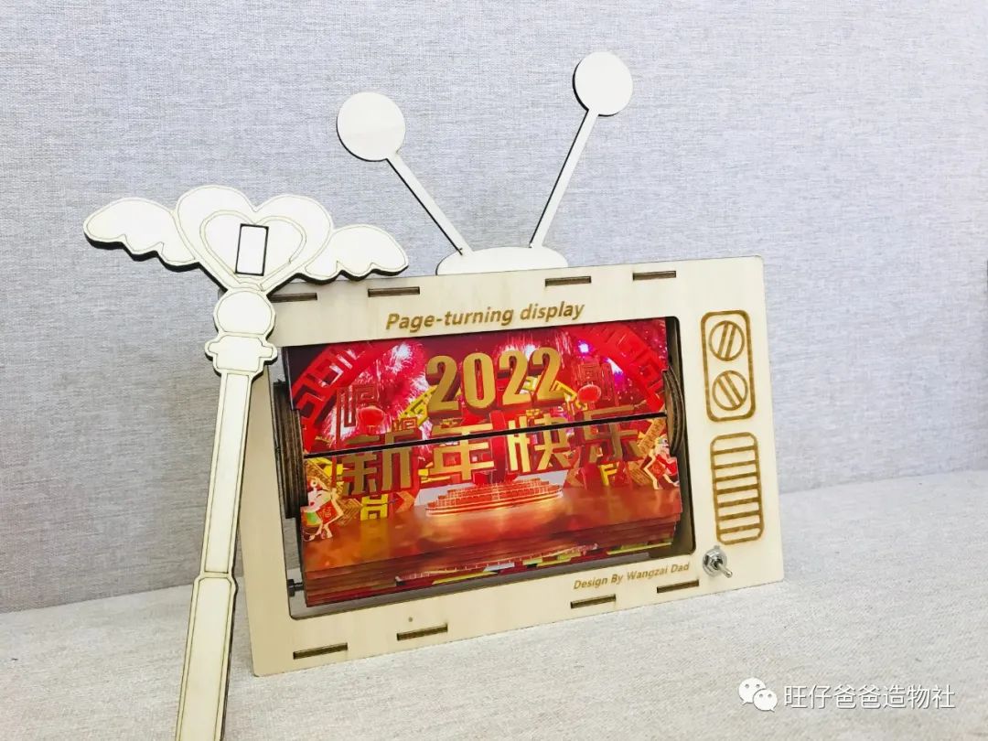
Figure 2 Page-Turning Animation Display
Since it is a display, it must have a screen. However, this screen is not electronic; it is an older flip-style, similar to the effect of quickly flipping through a book. In fact, the videos played on screens today also switch frames rapidly, so quickly that the human eye cannot perceive the change. Our page-turning animation display aims to restore this display principle.
Let’s first watch a video to see how the page-turning animation display works.
#Video Showcase#
#Design and Production#
We designed the page-turning animation display to resemble a vintage television set, using laser cutting technology to process linden wood and acrylic panels to create the appearance structure of the display. Figure 3 shows the effect diagram.

Figure 3 Simulation Diagram of Page-Turning Animation Display
#Plan Introduction#
From the simulation diagram above, we can see that the page-turning animation display consists of three parts: the rotating display part, the outer frame part, and the electronic control part.
For the driving motor of the rotating display part, there are many options available, such as stepper motors, DC reduction motors, servos, etc. Since the load of the rotating part is not very large and the speed requirement is not high, while still needing to precisely control the rotation angle, we chose the cost-effective 28BYJ-48 micro stepper motor, which can work with the ULN2003 driver, greatly reducing the difficulty of use and minimizing space. The stepper motor is shown in Figure 4.
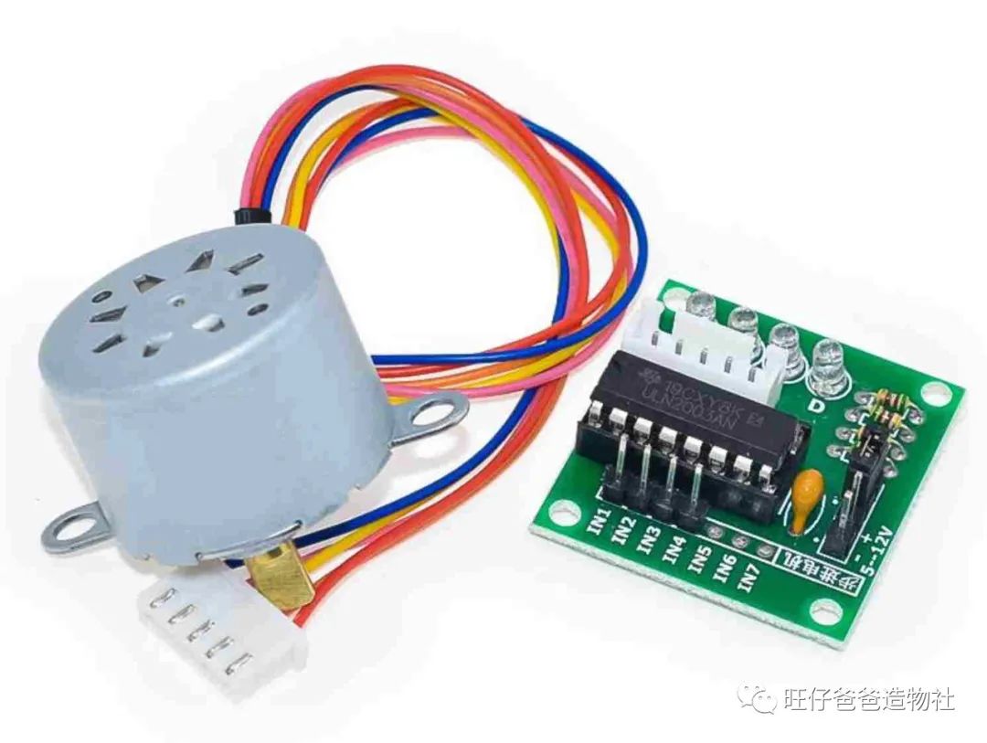
Figure 4 28BYJ-48 Micro Stepper Motor
After solving the key driving part, we chose the Arduino Nano as the main control board, and added a Hall sensor combined with a magnet to record the number of rotations, as detailed in Figure 5.
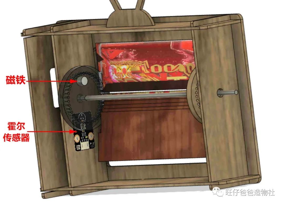
Figure 5Internal Diagram of Page-Turning Animation Display
Once the plan is confirmed, we can start designing the appearance structure of the page-turning animation display.
#Blueprint Design#
We used LaserMaker laser modeling software to design the blueprints.
You can download the modeling software from the official website:https://www.lasermaker.com.cn/

Figure 6 LaserMaker Software Download
After completing the download and installation, open the software, and the interface is shown in Figure 7.
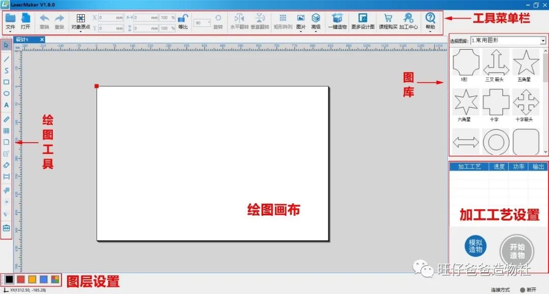
Figure 7 LaserMaker Software Interface
In the LaserMaker software, we designed the vintage television shape as shown in Figure 8. For the flipping part used to display images, we used a 1mm thick transparent acrylic panel, while other structural parts were made of 3mm thick linden wood. To enhance interactivity, we designed a magic wand as the start-stop switch for the page-turning display.
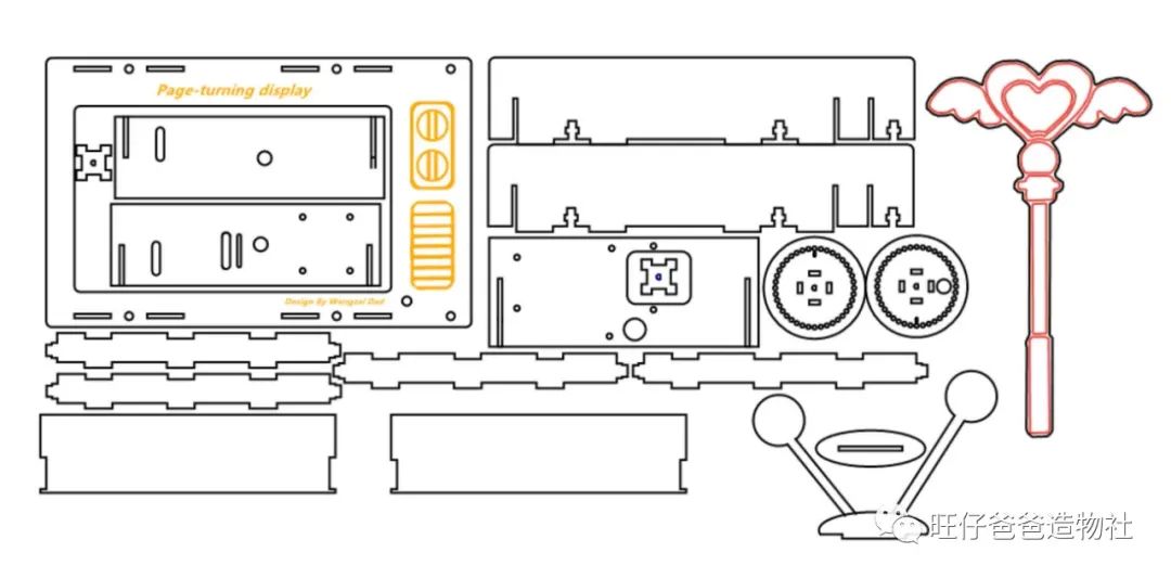
Figure 8 Design Drawing of Page-Turning Animation Display
As for the animation stickers to be displayed, you need to search online for New Year animation materials (or your favorite anime materials), modify them to the same size as the parts, print them out, and stick them on the acrylic panel.

Figure 9 Stickers and Acrylic Panel

Figure 10 Stickers Attached to the Acrylic Panel
#Processing Parts#
After completing the design of the blueprint, we used a laser cutter to process it, and the finished parts are shown in Figure 11.
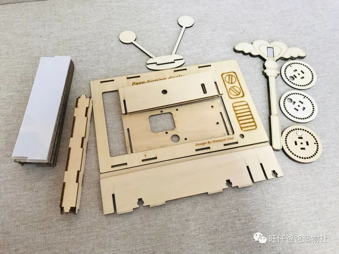
Figure 11 Physical Diagram of Parts After Laser Cutting
#Equipment List#
In addition to the appearance structure, this page-turning animation display also requires the following parts:
-
Arduino Nano controller with expansion board *1
-
Hall sensors *2
-
28BYJ-48 stepper motor *1
-
ULN2003 stepper motor driver *1
-
Switch *1
-
DC power interface *1
-
3mm linden wood *1 (40cm*60cm)
-
1mm transparent acrylic panel *2 (40cm*60cm)
-
Dupont wires (several)
-
3mm to 5mm coupling *1
-
20cm D-shaped shaft *1
-
Various hardware parts
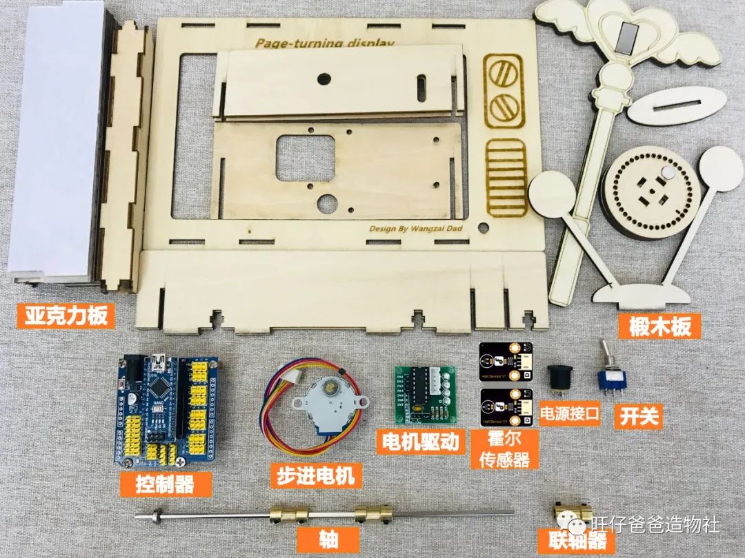
Figure 12 Equipment List for Page-Turning Animation Display
Once the equipment is ready, let’s take a look at how the electronic control part is connected.
#Circuit Wiring#
The circuit wiring for the page-turning animation display is shown in Figure 13.
The stepper motor is connected to the controller’s digital pins 4-7, and the two Hall sensors are connected to digital pins 2 and 3, with one Hall sensor serving as the start-stop switch and the other detecting how many turns the disk has made.
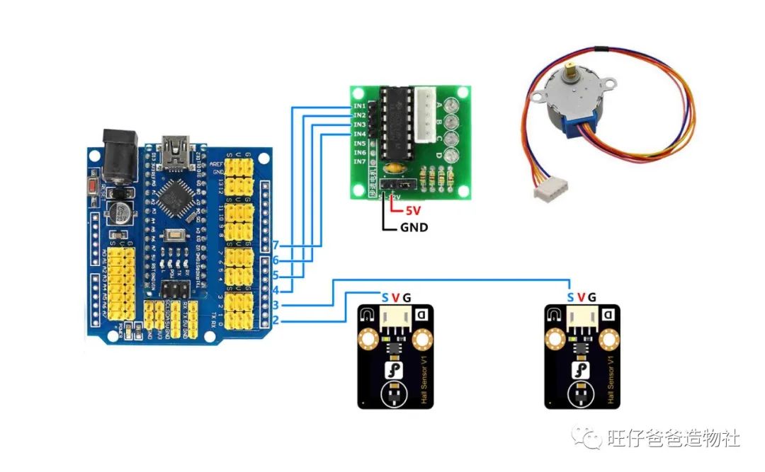
Figure 13Wiring Diagram for Page-Turning Animation Display
With everything ready, we can start assembling the project.
#Assembly#
The assembly of the page-turning animation display is not very complicated, but it still requires careful step-by-step installation.
Step 1: Install the Electronic Components
First, we install the switch for the page-turning display. We chose a somewhat vintage push-button switch for this project, installing it on the front wooden panel, as shown in Figures 14 and 15.
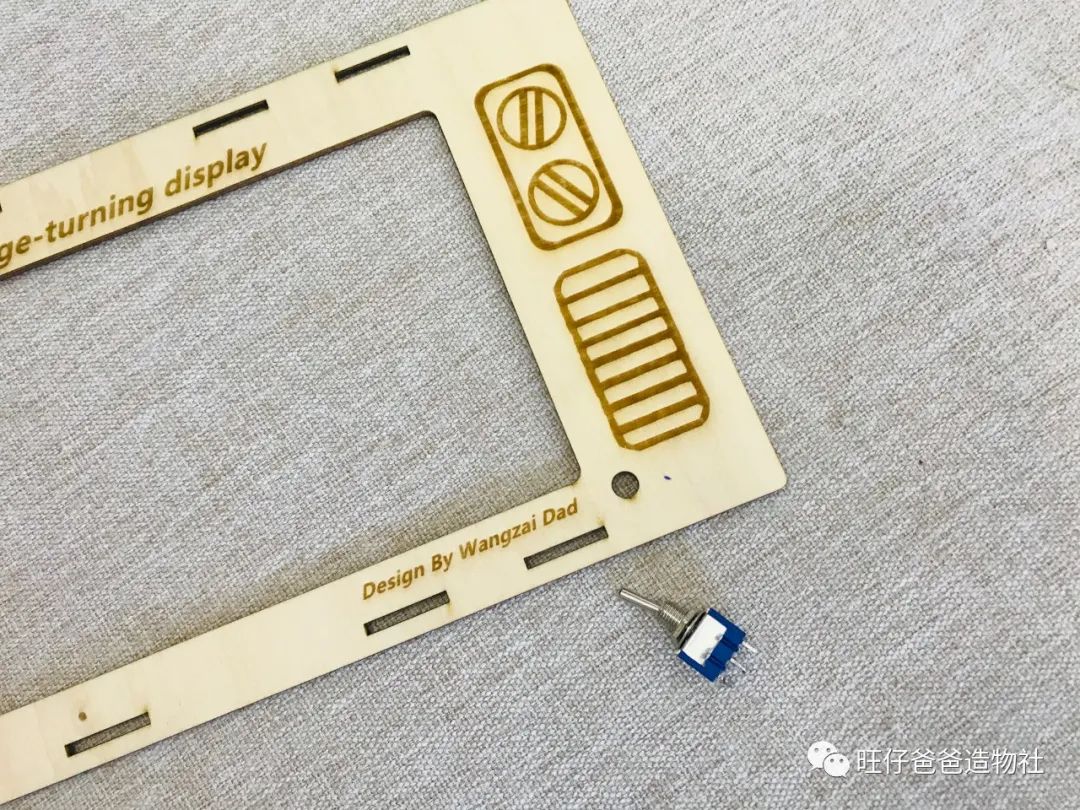
Figure 14 Installing the Push-Button Switch
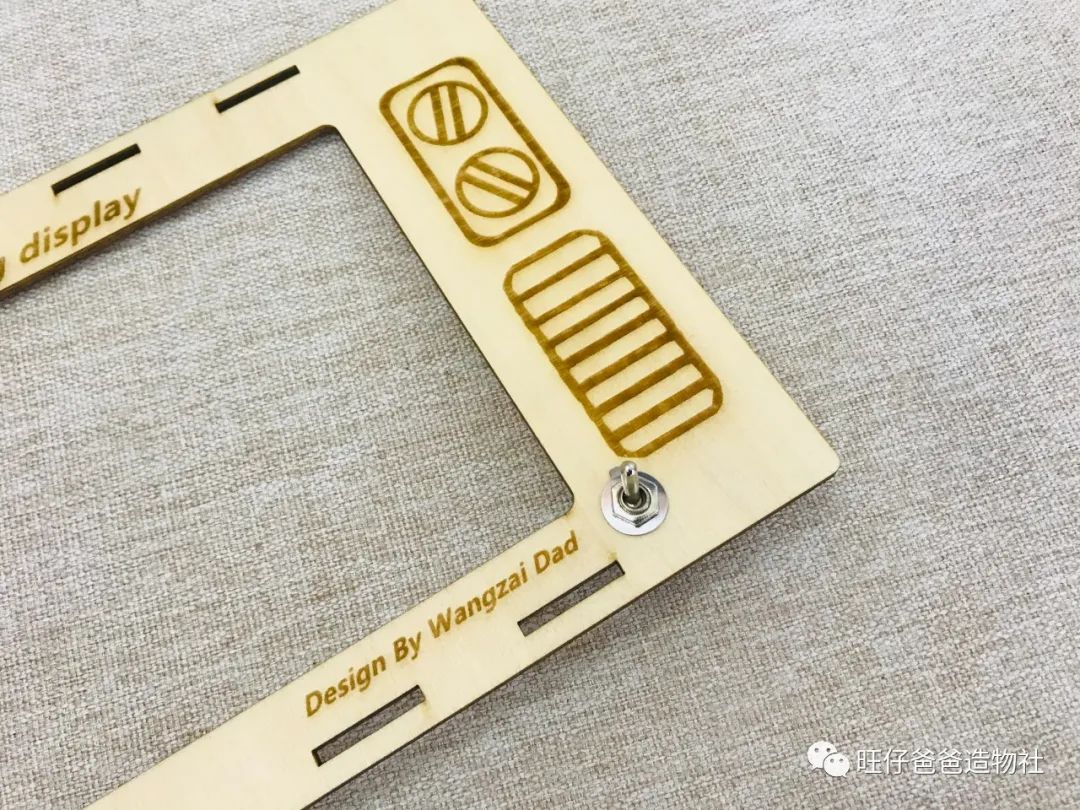
Figure 15 Push-Button Switch Installed
Next, we install the controller, stepper motor, driver, and power interface. The required parts are shown in Figure 16.
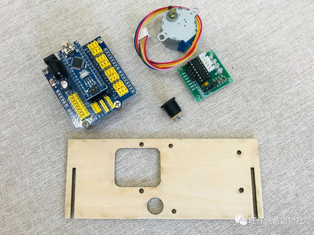
Figure 16 Electronic Components
The main control and stepper motor components are installed as shown in Figure 17.
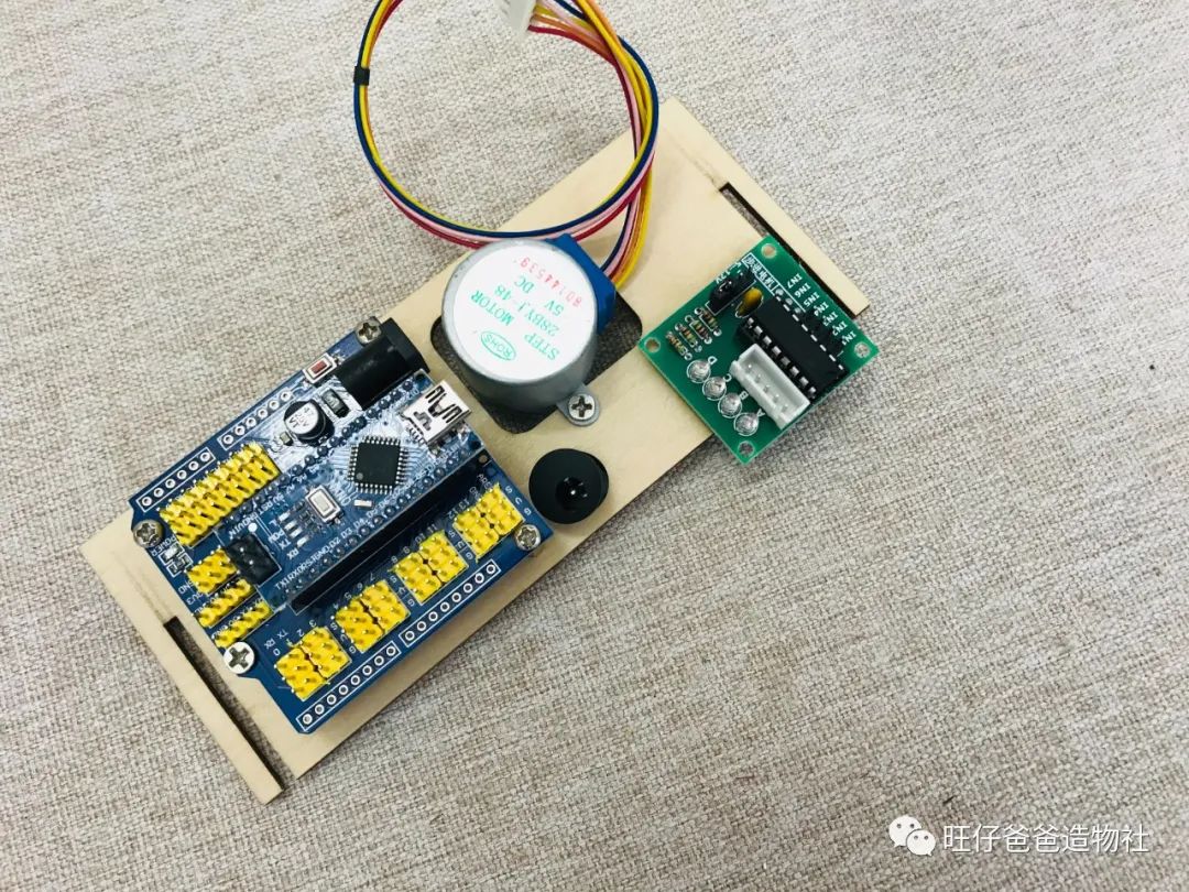
Figure 17 Main Control and Stepper Motor Installation Completed
Next, we install the Hall sensors used to record the number of rotations, as shown in Figure 18.
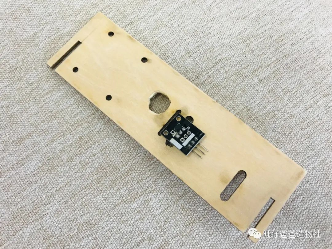
Figure 18 Hall Sensors Installed
Step 2: Assemble the Frame Structure
Once the electronic components are installed, the next step is to assemble the frame. The frame consists of 5 parts and can be assembled according to the slots.
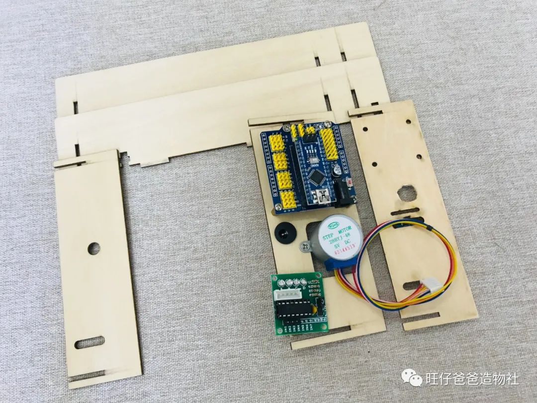
Figure 19 Parts Needed for Frame Assembly
The frame is completed as shown in Figure 20.
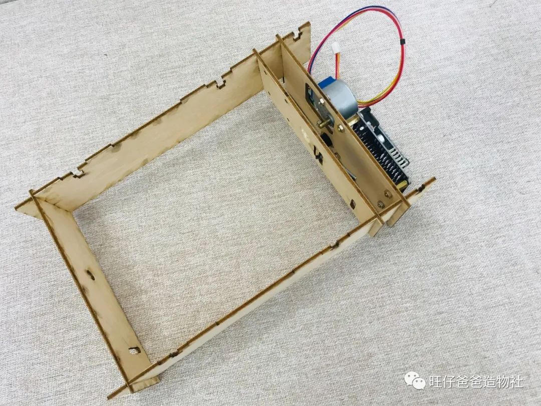
Figure 20 Frame Assembly Completed
After completing the frame, we need to install the rotating skeleton for the page display, with the required parts shown in Figure 21.
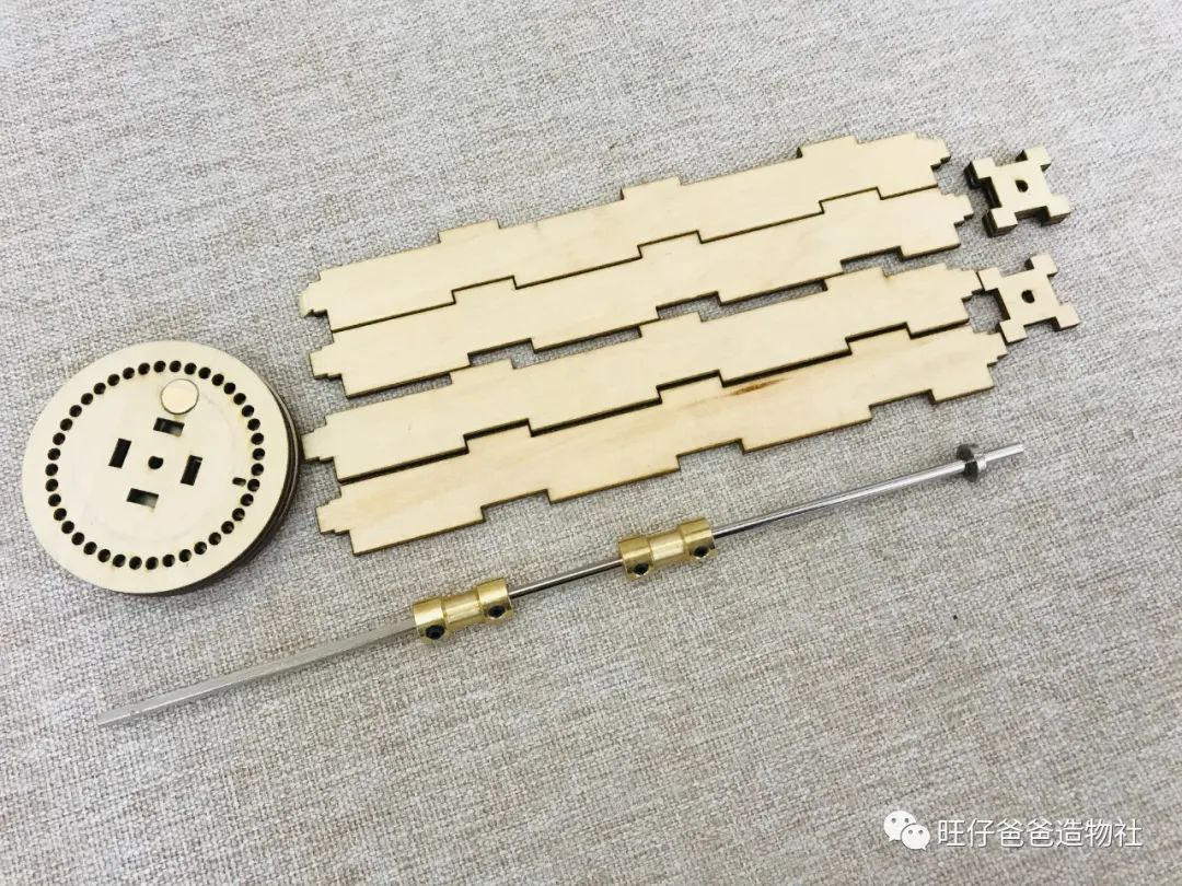
Figure 21 Parts Needed for Installing Rotating Skeleton
During assembly, the D-shaped shaft should be installed in the rectangular box, and the disks should be installed on both sides of the box. The completed installation is shown in Figure 22.
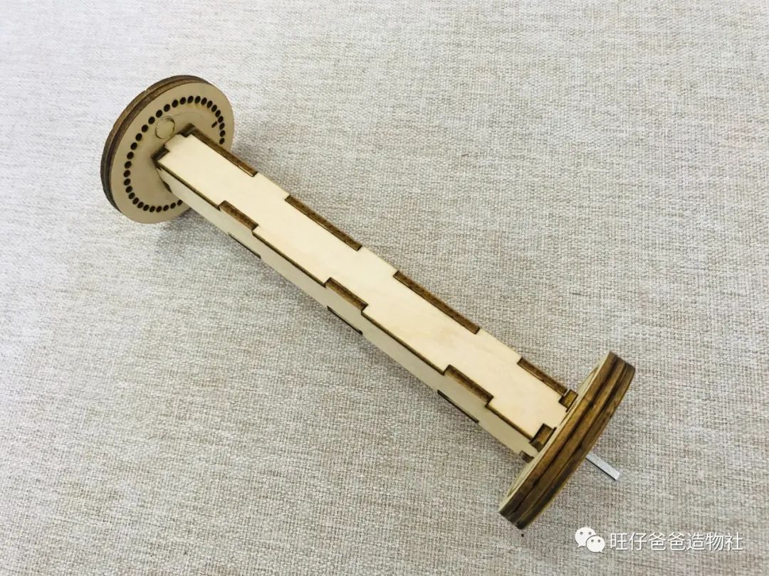
Figure 22 Rotating Skeleton Installed
Once the rotating skeleton is assembled, it needs to be combined with the frame, as shown in Figure 23.
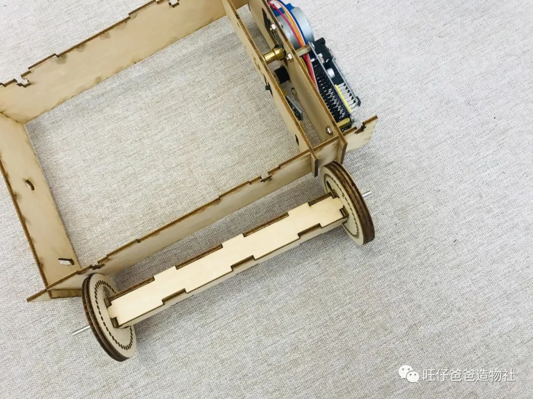
Figure 23 Rotating Skeleton Combined with Frame
Use a 5mm to 3mm coupling to connect the stepper motor with the D-shaped shaft, and on the other side, to ensure flexibility when the shaft rotates, we can install a bearing in the hole, as shown in Figure 24.
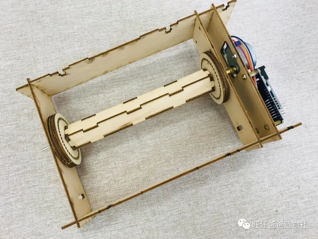
Figure 24 Rotating Skeleton and Frame Combined
The next step is to install the front wooden panel onto the frame.
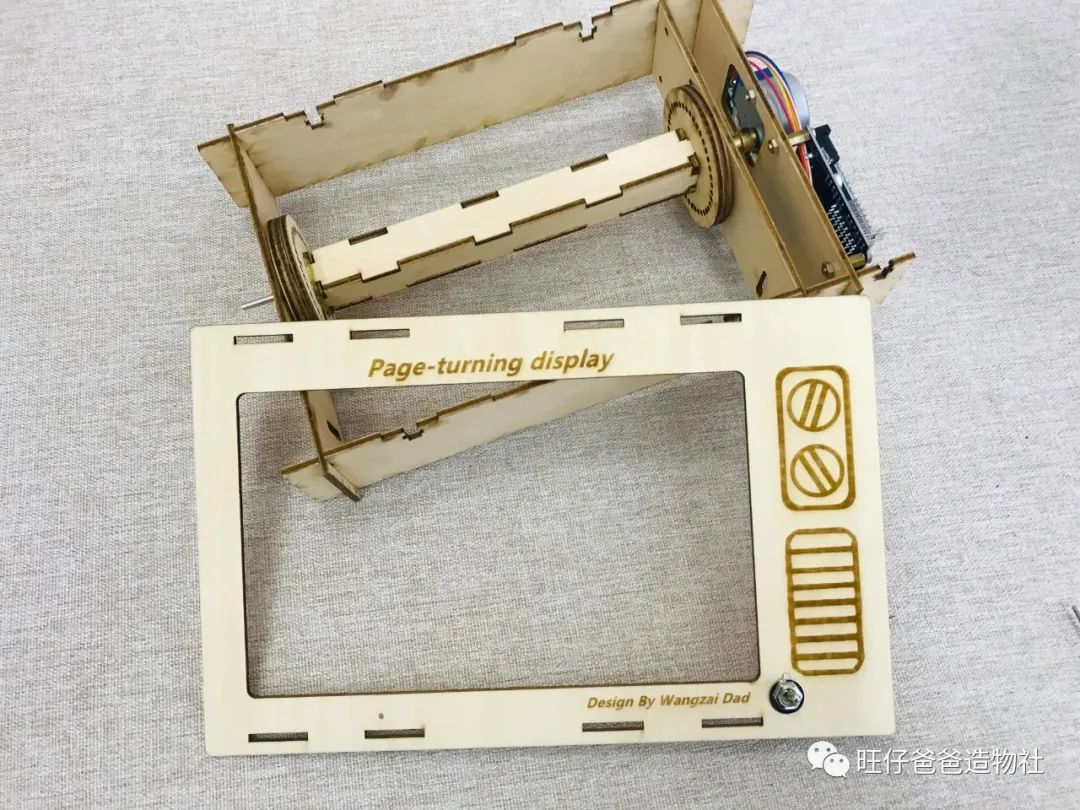
Figure 25 Front Wooden Panel Combined with Frame
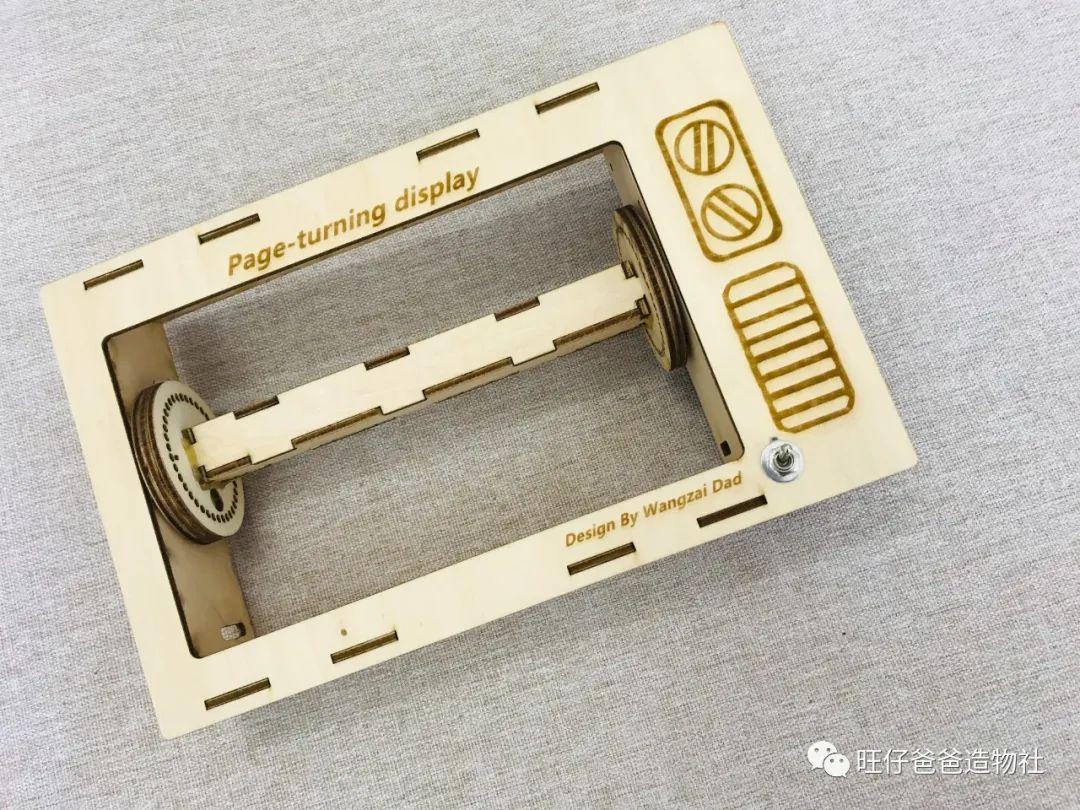
Figure 26 Front Wooden Panel Combined Completed
Step 3: Install the Display Part and Others
Now, the overall effect of the “television” is already there. If we could add an antenna, it would be even more “soulful.” Let’s install the antenna and the magic wand used to start and stop the display for the “television.”
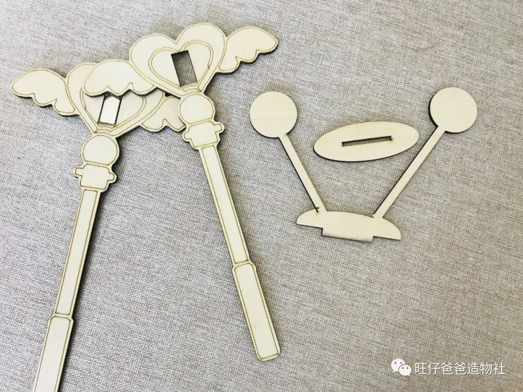
Figure 27 Parts Needed for Installing Antenna and Magic Wand
Don’t forget to install a magnet in the middle of the magic wand. The installation is completed as shown in Figure 28.
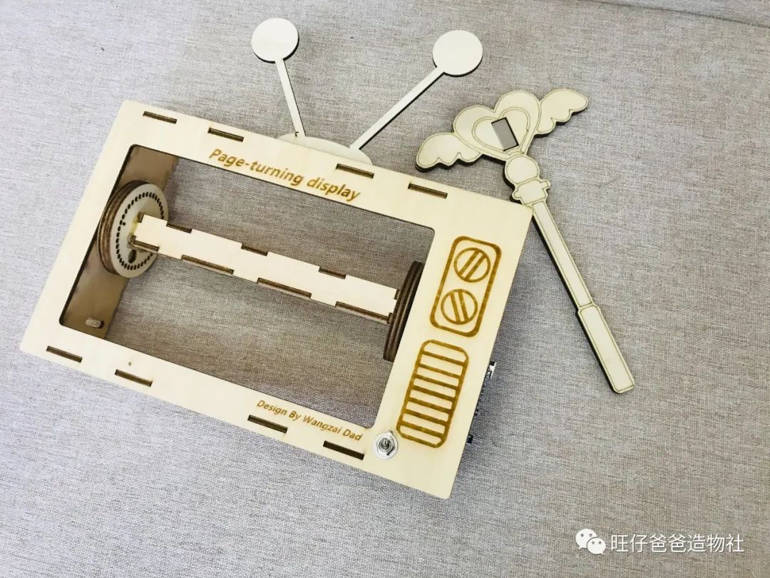
Figure 28 Antenna and Magic Wand Installed
Finally, we install the most important display image into the skeleton of the display, and the assembly of the page-turning animation display is complete.
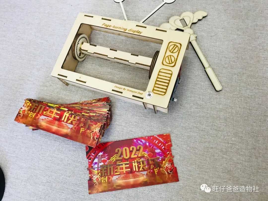
Figure 29 Display Image Installed
When installing the acrylic image, align it with the holes on both sides of the disk. The completed effect of the page-turning animation display is shown in Figure 30.
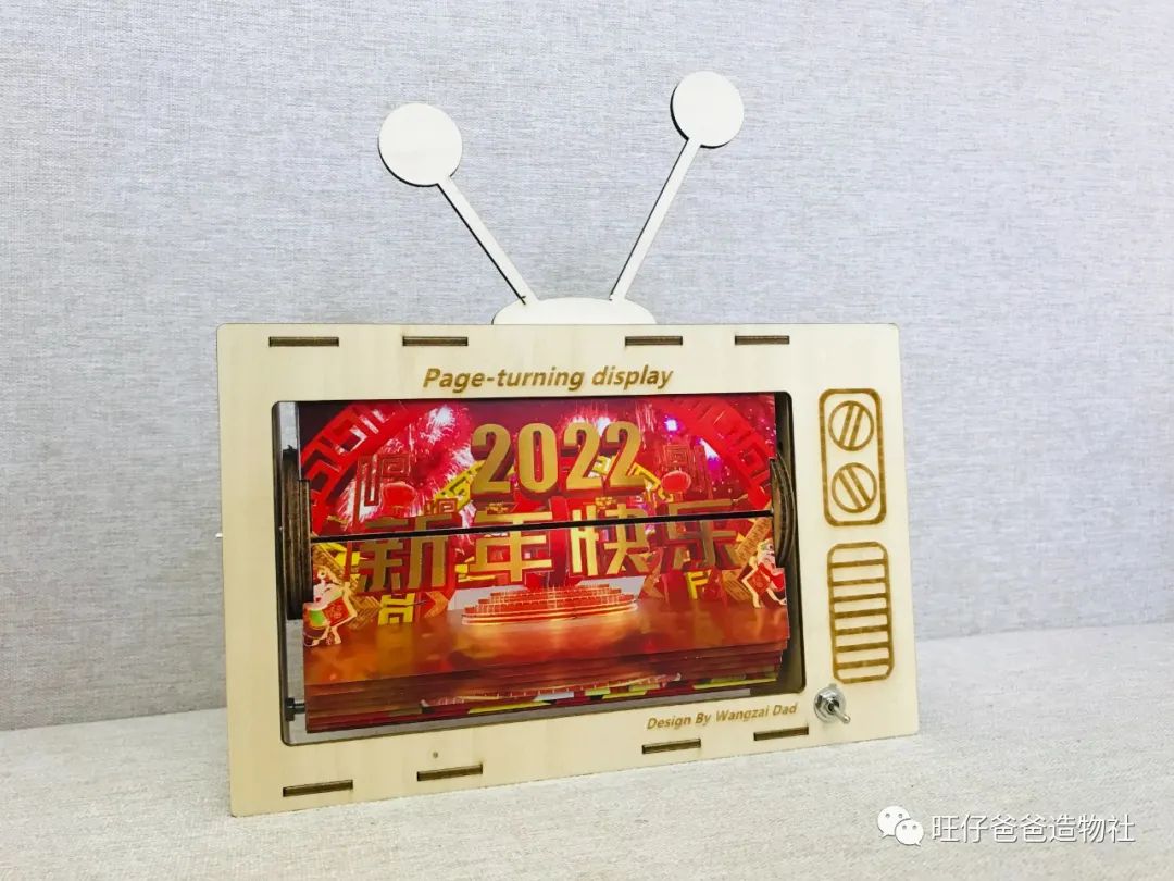
Figure 30 Display Image Installation Completed
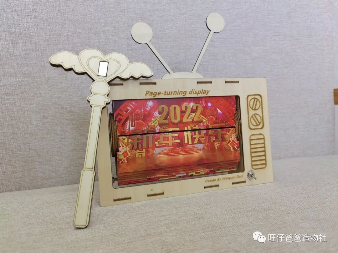
Figure 31
With the project fully assembled, we can now write the program to give it life.
#Program Design#
The program design for this project uses Arduino IDE as the programming environment. You can download the programming environment from the official website arduino.cc.

Figure 32
Of course, you can also download the latest Mixly graphical programming software from mixly.org, which integrates the Arduino IDE programming environment, saving a lot of configuration trouble.
#Programming Ideas#
This time, we made the page-turning animation display (Page-Turning Display), using the stepper motor to make the display turn, and using two Hall sensors to control the animation playback and record the number of rotations. The use of the stepper motor and Hall sensors is the key to the programming design of this project. We will complete it step by step according to the programming ideas.

Figure 33 Programming Mind Map
#Using Hall Sensors#
Background Knowledge
Hall sensors are based on the Hall effect and can be used to detect magnetic materials (magnets).
What is the Hall effect? The Hall effect was discovered by physicist Hall in 1879. When a magnetic field approaches a conductor with an electric current, the electrons in the conductor will deflect to one side due to the influence of the magnetic field, creating a potential difference in the conductor. This is the Hall effect, which can be used to detect magnetic materials.
Common types of Hall sensors include switch-type Hall sensors and linear Hall sensors.
Linear Hall sensors output analog signals, while switch-type Hall sensors output digital signals.
For this project, we only need to use the Hall sensors to control the start and stop of the page-turning animation display, so a switch-type Hall sensor is sufficient.
The programming method for Hall sensors is simple; it just needs to detect whether a magnet is present.
We input the following program in the programming environment to test the state of the Hall sensor:
#define Hall_START 2 //Hall sensor pinint START;//Variable to store start statevoid setup(){ pinMode(Hall_START, INPUT);//START Serial.begin(9600); }void loop(){ START = digitalRead(Hall_START);//Store the status of the Hall sensor Serial.println(START); delay(1000);}The program runs with the following results in Figure 34.
When the magnet is close, the signal is 0, and when the magnet is away, the signal is 1.
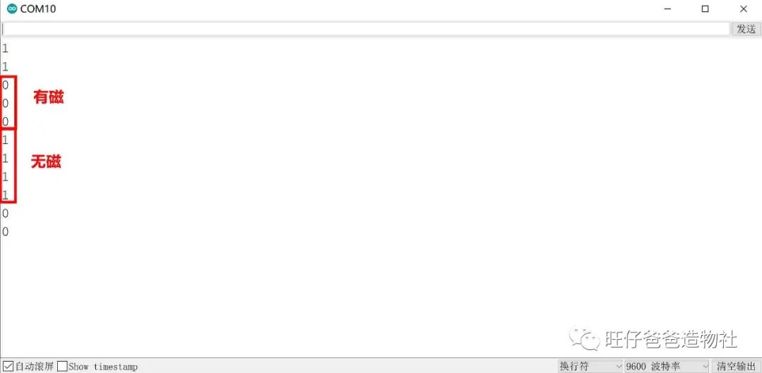
Figure 34 Hall Sensor Test
Similarly, we can test the second Hall sensor using the same method.
We will continue to modify the program based on the existing one:
#define Hall_START 2 //Hall sensor pin#define Hall_END 3 //Hall sensor pinint START;//Variable to store start stateint END;//Variable to store end statevoid setup(){ pinMode(Hall_START, INPUT);//START pinMode(Hall_END, INPUT);//END Serial.begin(9600);}void loop(){ START = digitalRead(Hall_START);//Store the status of Hall sensor 1 END = digitalRead(Hall_END);//Store the status of Hall sensor 2 Serial.print(F("Hall Sensor 1 Status:")); Serial.println(START); delay(1000); Serial.print(F("Hall Sensor 2 Status:")); Serial.println(END); delay(1000);}The effect after downloading and running the program is shown in Figure 35.
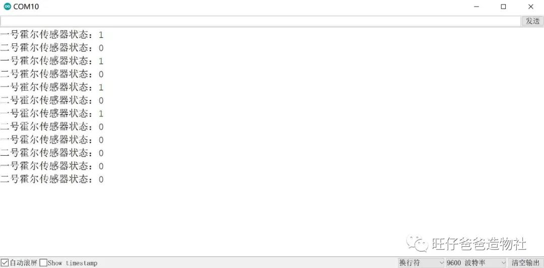
Figure 35 Both Hall Sensors Tested Simultaneously
Thus, both Hall sensors can be controlled.
Next, we will enrich the program by setting it to start working when the magnet approaches the Hall sensor for more than 0.5 seconds. The program is as follows:
#define Hall_START 2 //Hall sensor pin#define Hall_END 3 //Hall sensor pin#define OVER 1 //Determine if it has entered the final stageint START;//Variable to store start stateint END;//Variable to store end statebool is_working = false;//Workingbool is_free = true;//Idleint count=0;//Counterint SPEED=0;//speedchar MODEL; //Modevoid setup(){ pinMode(Hall_START, INPUT);//START pinMode(Hall_END, INPUT);//END Serial.begin(9600);}void loop(){ if(START == 1 && digitalRead(Hall_START) == 0)//Detect the button state twice { delay(500); if ( digitalRead(Hall_START) == 0 && is_free == true) //If the device is idle, enter working mode { is_free = false; is_working = true; } } START = digitalRead(Hall_START);//Store the status of Hall sensor 1 END = digitalRead(Hall_END);//Store the status of Hall sensor 2 //Start working if(is_free == false && is_working == true ) { Serial.println(F("Working")); //Count the counter, ignore the first detection state count++; if(count > 500) { MODEL = OVER; } } //End working if (MODEL == OVER && END == 0) { Serial.println(F("End Working")); count = 0;//Reset counter is_working = false;//Reset working indicator variable is_free = true;//Reset idle indicator variable MODEL = 0;//Reset state }}In the program, we set the “START” and “END” variables to store the values of the two Hall sensors, and the “is_free” and “is_working” variables to mark the working state. The “MODEL” variable is used to store the working status. When a magnet approaches Hall sensor 1 for more than 0.5 seconds, it enters working mode, and the “count” variable starts counting. When the count exceeds 500, it ends working and resets all variable states.
The running result after downloading the program is shown in Figure 36. When the magnet approaches the Hall sensor for more than 0.5 seconds, it starts counting, and when the count exceeds 500, it stops working.
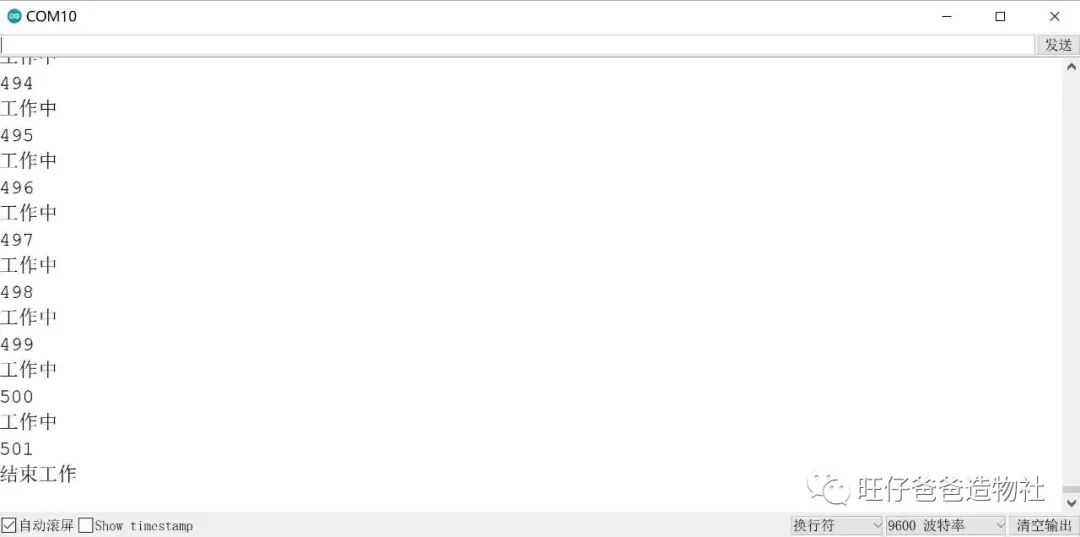
Figure 36 Hall Sensor Start-Stop Test
Thus, we have achieved the function of using a magnet to control the start and stop. Next, we just need to add the stepper motor rotation program to achieve the real page-turning action.
Now, let’s learn how to control the stepper motor.
#Stepper Motor Knowledge#
Background Knowledge
This time, we chose the 28BYJ-48 stepper motor, which is fully named the permanent magnet unipolar four-phase stepper motor. Such a complex name can be a bit daunting.
Let’s first look at the origin of the name 28BYJ-48 stepper motor.
-
28: The effective maximum outer diameter of the stepper motor is 28 millimeters.
-
B: Indicates it is a stepper motor.
-
Y: Indicates it is permanent magnet type.
-
J: Indicates it is a reduction type (reduction ratio 1:64).
-
48: Indicates four-phase eight-step.
In other words, the meaning of 28BYJ-48 is a permanent magnet reduction four-phase eight-step stepper motor with an outer diameter of 28 millimeters. Sounds a bit complicated? Don’t worry, we’ll break it down.
Generally, a motor consists of a stator and a rotor. Each tooth of the rotor carries a permanent magnet, which is the concept of permanent magnet type.
The stator is on the outer ring, and there are 8 teeth on the stator, each wound with a coil, two at a time, creating 4 phases, which is the concept of four phases. As for the eight steps, we won’t go into detail; you can simply understand it as the order of energizing the 4 groups of coils.
Next, let’s explain the concept of “reduction” in the name. Figure 37 shows the disassembled view of the 28BYJ-48 stepper motor.
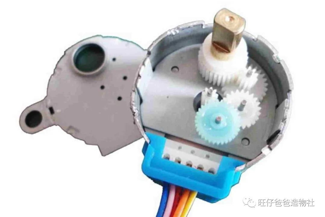
Figure 37 28BYJ-48 Stepper Motor Internal View
From the image, you can see that the small white gear in the center is the rotor shaft of the stepper motor. A small gear drives a large gear for one level of reduction. There are a total of 4 levels of reduction in the motor shown in the image. So what is the total reduction ratio?
Looking back at the reduction ratio parameter in the motor specification sheet, it is 1:64, which means the rotor needs to turn 64 times for the output shaft to turn once. Regardless of which manufacturer produces the motor, as long as the model is 28BYJ-48, the nominal reduction ratio is 1:64.
We will stop here for the basic control principle.
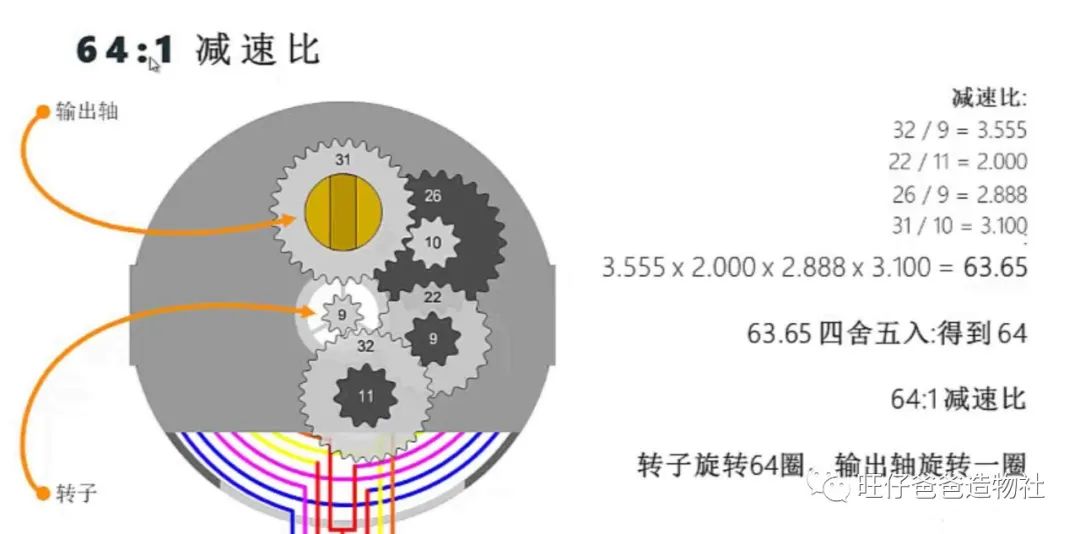
Figure 38 Illustration of Stepper Motor Reduction Ratio
In reality, controlling a stepper motor with just a controller is quite difficult; a driver is needed to drive the stepper motor. The ULN2003 driver and the 28BYJ-48 stepper motor are inseparable partners that usually appear together.
Now that we are familiar with the 28BYJ-48 stepper motor, let’s write a program to control the stepper motor. We can choose from the built-in 【Stepper】 library in Arduino IDE and the 【AccelStepper】 third-party library.
Since the built-in 【Stepper】 library cannot run other programs while controlling the stepper motor, we need to use the simple, powerful 【AccelStepper】 third-party library, allowing Arduino to control the stepper motor while performing other tasks.
Installing the AccelStepper Library
In the Arduino IDE programming environment, click on the 【Library Manager】 option in the Tools menu, enter 【AccelStepper】 in the input field, and click install, as shown in Figure 39.
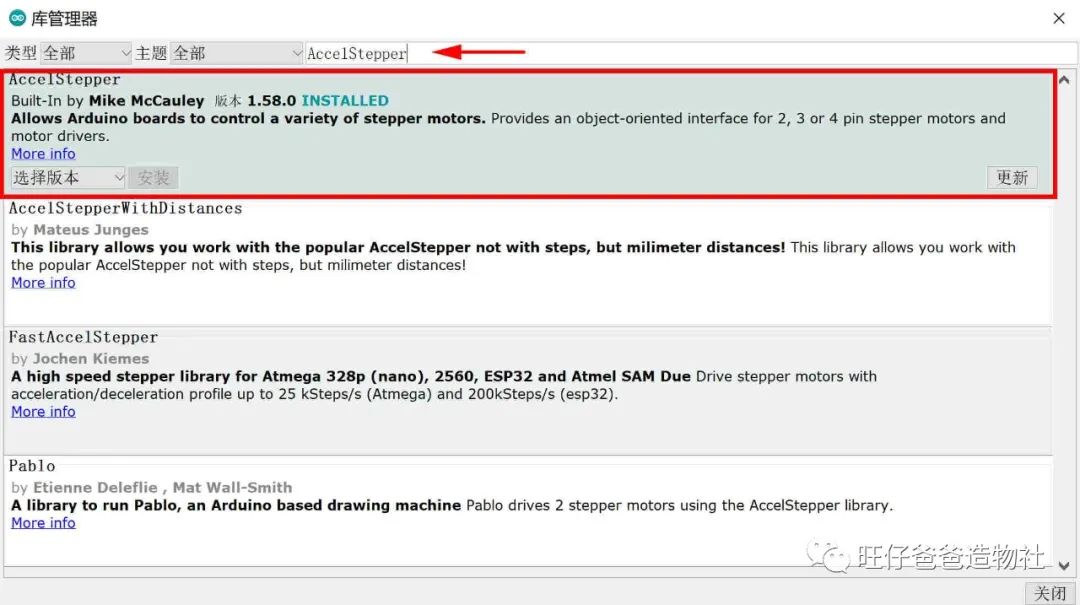
Figure 39 Installing the AccelStepper Library
Once the installation is complete, you can use this library to control the stepper motor.
We input the following program in the programming environment:
#include "AccelStepper.h"// Define motor stepping mode#define FULLSTEP 4 //Full step parameter#define HALFSTEP 8 //Half step parameter// Define stepper motor pins#define motor1Pin1 4 // Pin in1 connected to ULN2003 driver for 28BYJ48#define motor1Pin2 5 // Pin in2 connected to ULN2003 driver for 28BYJ48#define motor1Pin3 6 // Pin in3 connected to ULN2003 driver for 28BYJ48#define motor1Pin4 7 // Pin in4 connected to ULN2003 driver for 28BYJ48// Define stepper motor object// Define ULN2003 driver pin order as in1-in3-in2-in4// Motor set to run in full-step modeAccelStepper stepper(FULLSTEP, motor1Pin1, motor1Pin3, motor1Pin2, motor1Pin4);void setup(){ stepper.setMaxSpeed(500.0); // Maximum speed of motor 500 stepper.setAcceleration(50.0); // Acceleration of motor 50.0 Serial.begin(9600); }void loop(){ if ( stepper.currentPosition() == 0 ) { // Motor rotates one circle stepper.moveTo(2048); } else if ( stepper.currentPosition() == 2048 ) { // Motor rotates one circle stepper.moveTo(0); } stepper.run(); // Motor runs}In the program, we set the maximum running speed of the stepper motor using 【setMaxSpeed】, set the acceleration of the stepper motor using 【setAcceleration】, get the current position of the stepper motor using 【currentPosition】, and the 【moveTo】 command can set the absolute target position for the stepper motor, i.e., to rotate to a specified angle.
Here, the position of the stepper motor when powered on is 0.
After running the program, we will see that the stepper motor rotates one circle and stops. Why is stepper.moveTo(2048) one rotation? Here, 2048 refers to what?
The step angle of the four-phase eight-step stepper motor is 11.25°. It takes 32 steps for the rotor to complete one rotation (360/11.25=32), and with a reduction ratio of 1:64, the output shaft needs 32*64=2048 steps to complete one rotation.
Thus, the 2048 in stepper.moveTo(2048) is actually the number of steps the output shaft needs to take to complete one rotation, which is under the full-step parameter “#define FULLSTEP 4”. If using half-step “#define HALFSTEP 8”, the rotor would need 64 steps to complete one rotation, requiring 4096 steps for the output shaft to complete one rotation.
Additionally, the 【AccelStepper】 library provides some other commonly used functions, as follows:
Common Functions and Operations
-
setCurrentPosition – Reset the initial position of the stepper motor
Using the setCurrentPosition function, you can modify the value of the current position. For example, if the current position of the stepper motor is 0, inputting stepper.setCurrentPosition(512) will change the original position of 0 to 512.
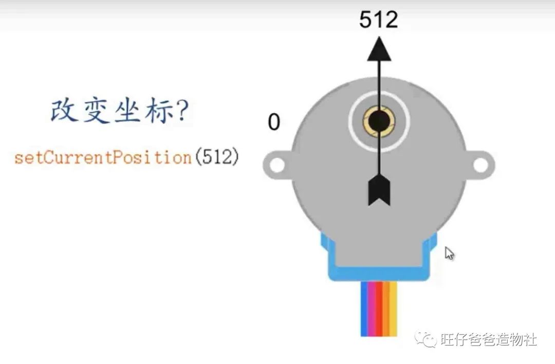
Figure 40 Illustration of setCurrentPosition Function
-
move – Set the relative target position for the stepper motor
stepper.move(1024); // Using move function to make the stepper motor run the corresponding number of steps.For example, if the current position of the stepper motor is 0, move(512) can make the stepper motor turn 512 steps to point to position 512. Another move(512) command would make the stepper motor point to position 1024.
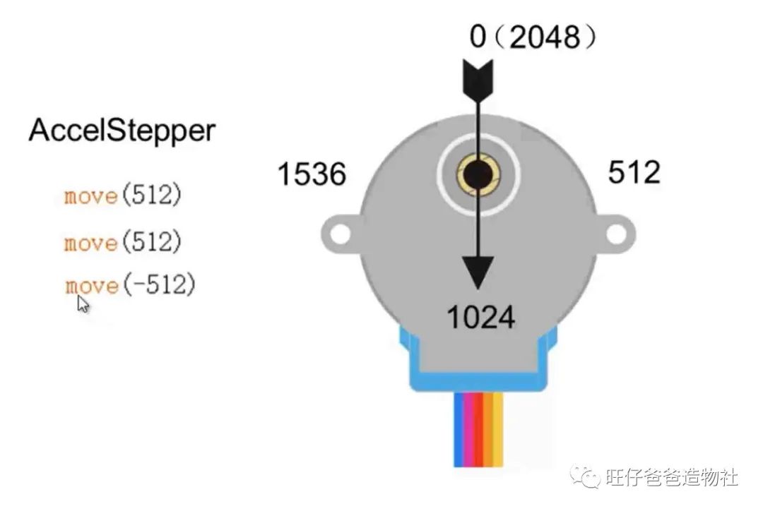
Figure 41 Illustration of move Function
-
moveTo – Set the absolute target position for the stepper motor
Using the moveTo command, you can make the stepper motor rotate to a specified angle. For example, moveTo(1024) can make the stepper motor point to position 1024. If you input the moveTo(1024) command again, the stepper motor will not move as it is already at position 1024.
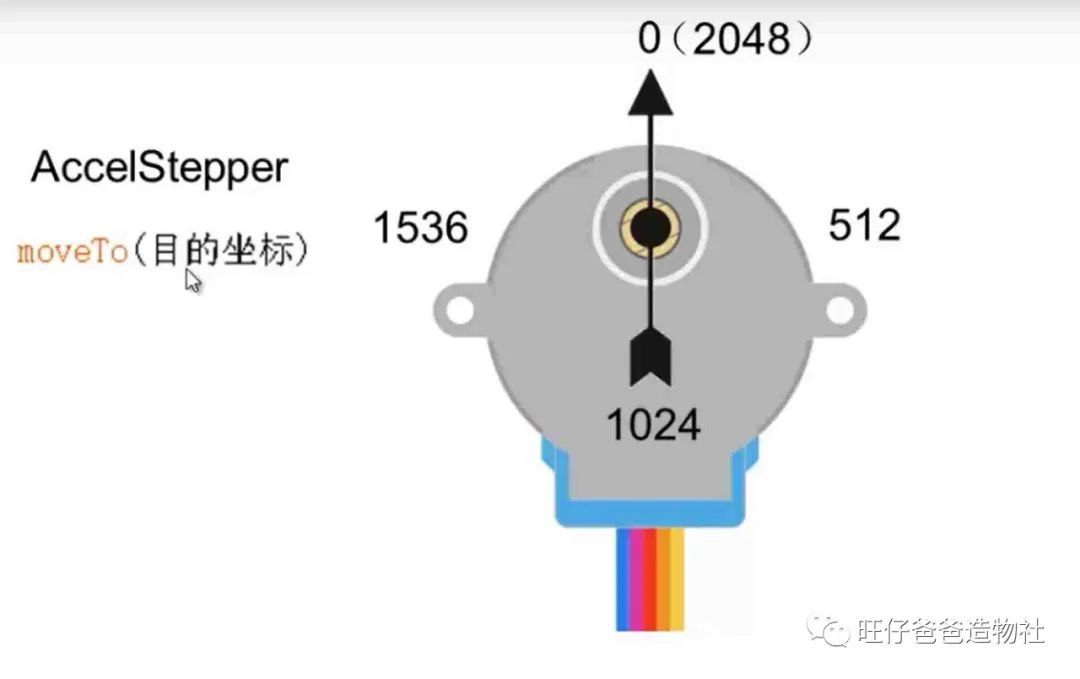
Figure 42 Illustration of moveTo Function
-
runToNewPosition – Motor runs to the user-specified position value, with the target position being absolute.
stepper.runToNewPosition(2048); // Using runToNewPosition function to make the motor run to the user-specified position value.The runToNewPosition command is similar to the previous moveTo command, but the difference is that the runToNewPosition command will not continue executing subsequent program content until the stepper motor reaches the target position.
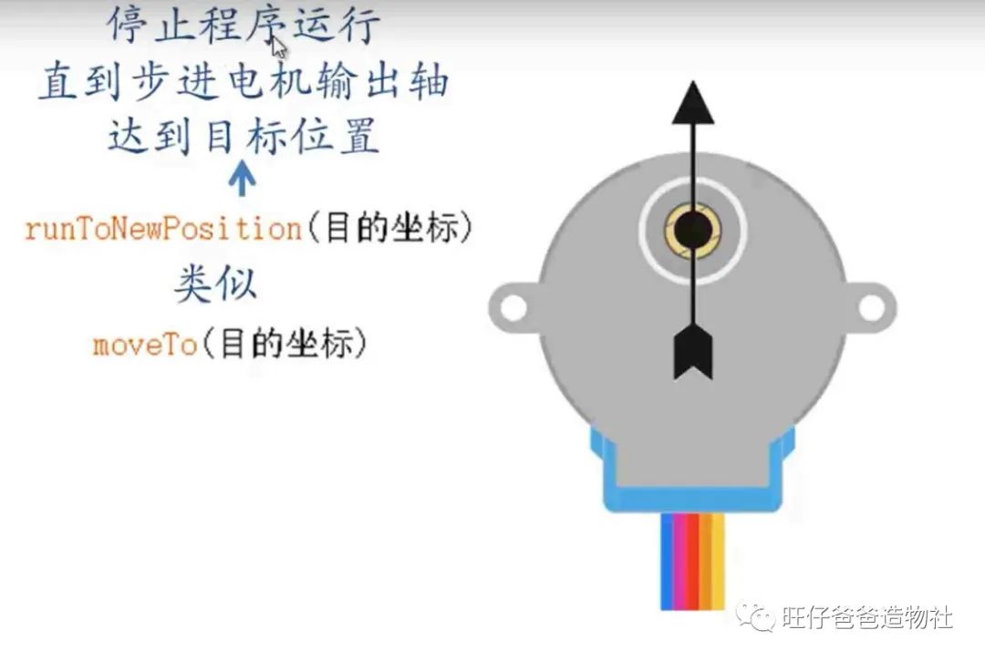
Figure 43 Illustration of runToNewPosition Function
-
setSpeed – Set the running speed of the stepper motor
-
run – Stepper motor runs (acceleration and deceleration mode)
-
runSpeed – Stepper motor runs (constant speed mode)
If you want the stepper motor to rotate at a constant speed, you need to use setSpeed to set the running speed of the stepper motor and the runSpeed() function.
For example, inputting the following two lines of code will make the stepper motor run at a constant speed of 300:
stepper.setSpeed(300); // Initialize motor speed to 300stepper.runSpeed();The above is an introduction to the commonly used functions of the AccelStepper library (here, we reference the materials provided by the Taiji Maker Team, thanks to Taiji Maker for their contributions to the maker community). The AccelStepper library has many functions not listed here. We believe that mastering the above functions will make it easier to understand and master other functions of the AccelStepper library. For more information on using the AccelStepper library, please refer to http://www.airspayce.com/mikem/arduino/AccelStepper/index.html.
In this page-turning animation display, we only need to make the stepper motor run at a constant speed.
We will combine the previous Hall sensor program with the stepper motor program to complete the program control for the page-turning animation display.
The complete program is as follows:
#include "AccelStepper.h"// Define motor stepping mode#define FULLSTEP 4 //Full step parameter#define HALFSTEP 8 //Half step parameter// Define stepper motor pins#define motor1Pin1 4 // Pin in1 connected to ULN2003 driver for 28BYJ48#define motor1Pin2 5 // Pin in2 connected to ULN2003 driver for 28BYJ48#define motor1Pin3 6 // Pin in3 connected to ULN2003 driver for 28BYJ48#define motor1Pin4 7 // Pin in4 connected to ULN2003 driver for 28BYJ48#define Hall_START 2 //Hall sensor pin#define Hall_END 3 //Hall sensor pin#define OVER 1 //Determine if it has entered the final stage// Define stepper motor object// Define ULN2003 driver pin order as in1-in3-in2-in4// Motor set to run in full-step modeAccelStepper stepper(FULLSTEP, motor1Pin1, motor1Pin3, motor1Pin2, motor1Pin4);int START;//Variable to store start stateint END;//Variable to store end statebool is_working = false;//Workingbool is_free = true;//Idleint count=0;//Counterint SPEED=0;//speedchar MODEL; //Modevoid setup(){ pinMode(Hall_START, INPUT);//START pinMode(Hall_END, INPUT);//END stepper.setMaxSpeed(500.0); // Maximum speed of motor 500 stepper.setSpeed(0); // Initialize motor speed to 0 Serial.begin(9600); //Reset to initial position while(digitalRead(Hall_END) == 1) { stepper.setSpeed(100); stepper.runSpeed(); } stepper.setSpeed(0); stepper.runSpeed(); }void loop(){ if(START == 1 && digitalRead(Hall_START) == 0)//Detect the button state twice { delay(500); if ( digitalRead(Hall_START) == 0 && is_free == true) //If the device is idle, enter working mode { is_free = false; is_working = true; } } START = digitalRead(Hall_START);//Store the status of Hall sensor 1 END = digitalRead(Hall_END);//Store the status of Hall sensor 2 //Start working if(is_free == false && is_working == true ) { SPEED = 100; //Count the counter, ignore the first detection state if(count > 500) { MODEL = OVER; } count++; } //End working if (MODEL == OVER && END == 0) { SPEED = 0;//Reset speed count = 0;//Reset counter is_working = false;//Reset working indicator variable is_free = true;//Reset idle indicator variable MODEL = 0;//Reset state } Serial.println(count); stepper.setSpeed(SPEED); stepper.runSpeed();}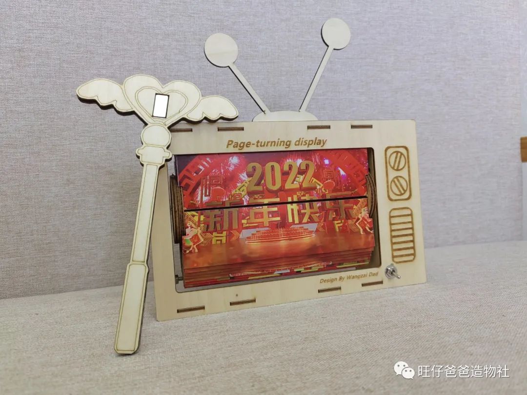
Figure 44
At this point, the page-turning animation display is fully completed.
Benefits
Reply with the keyword “Page-Turning Display” in the public account backend to obtain the blueprint file.
#Conclusion#
In this project, we learned the working principle of Hall sensors and how to use the 28BYJ-48 stepper motor. With these skills, more interesting animation content can be easily displayed, such as various anime-themed materials. So what are you waiting for? Go ahead and give it a try!
The Year of the Tiger Spring Festival is just around the corner. Finally, I wish everyone a happy and healthy new year, with all wishes fulfilled.
Creating makes life better. See you next time!