In the actual application of industrial automation equipment, various communications are essential, such as PN communication, S7 communication, MODBUS TCP communication, and MODBUS communication, etc.; among them, MODBUS communication is the most widely used since it is an open, free, and universal communication protocol. However, often during equipment debugging on the industrial site, communication may fail for no reason or may not be established at all. At this point, using a debugging tool to test the possible factors is beneficial; furthermore, for beginners who want to learn MODBUS communication, testing and learning can also be done using debugging tools without adding communication instruments.
Below, we will use the Siemens 200SMART PLC as the MODBUS master station and utilize a debugging tool as the slave station for communication testing.
The communication task is shown in Figure 1.
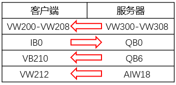
Figure 1: Data Interaction Diagram
One RS485 to USB connector, one RS485 male connector, two cables, as shown in Figure 2; one PC, one 200SMART, and one communication network cable. The CPU body port pin description is shown in Figure 3.
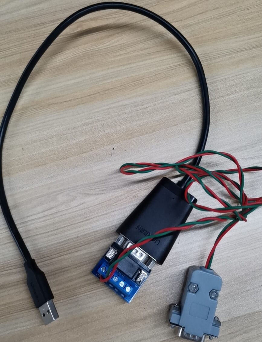
Figure 2: USB to Serial Port Hardware
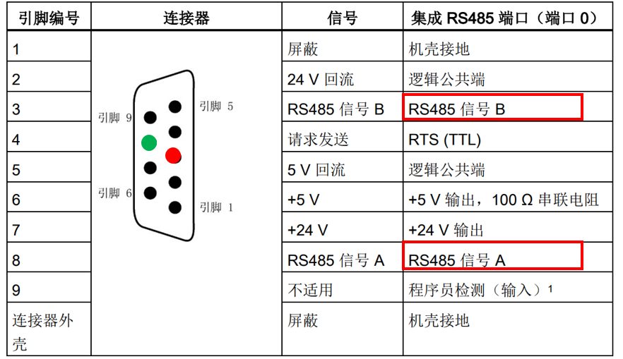
Figure 3: Serial Port Pin Description
Communication commands: The Siemens 200SMART library commands automatically integrate MODBUS communication library commands. Different library commands are called based on different ports. This example will use two master station commands; Figure 4 shows the master station initialization command; Figure 5 shows the master station data read/write command.
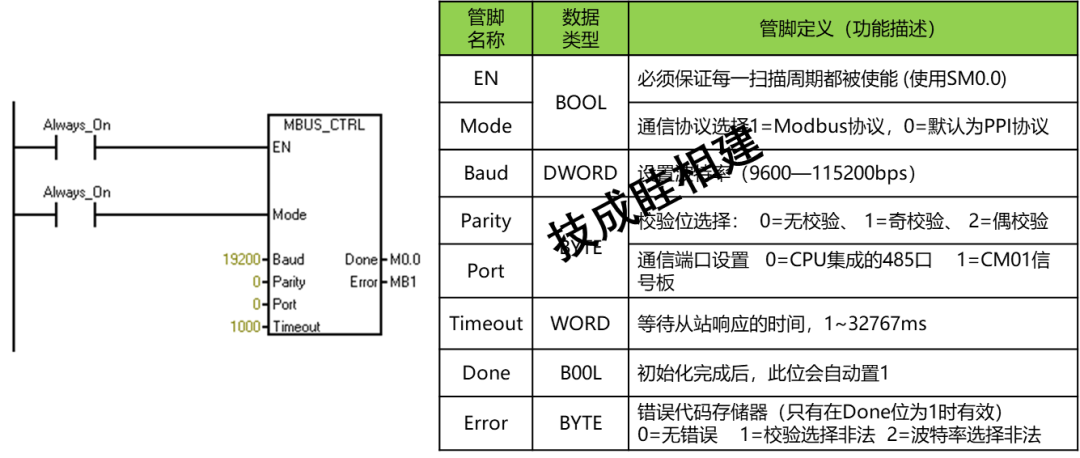
Figure 4: Master Station Initialization Command
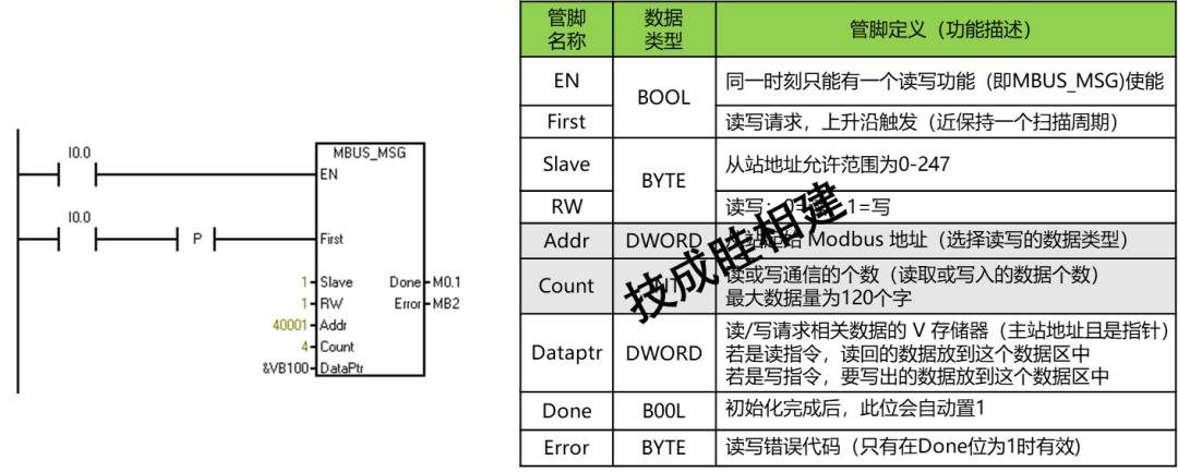
Figure 5: Master Station Data Read/Write Command
1. Call the MODBUS master station library commands for programming on the SMART side, as shown in Figures 6/7.
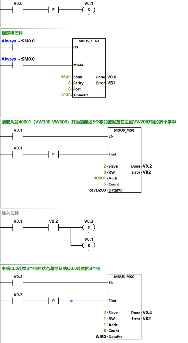
Figure 6: Master Station Data Read/Write Program
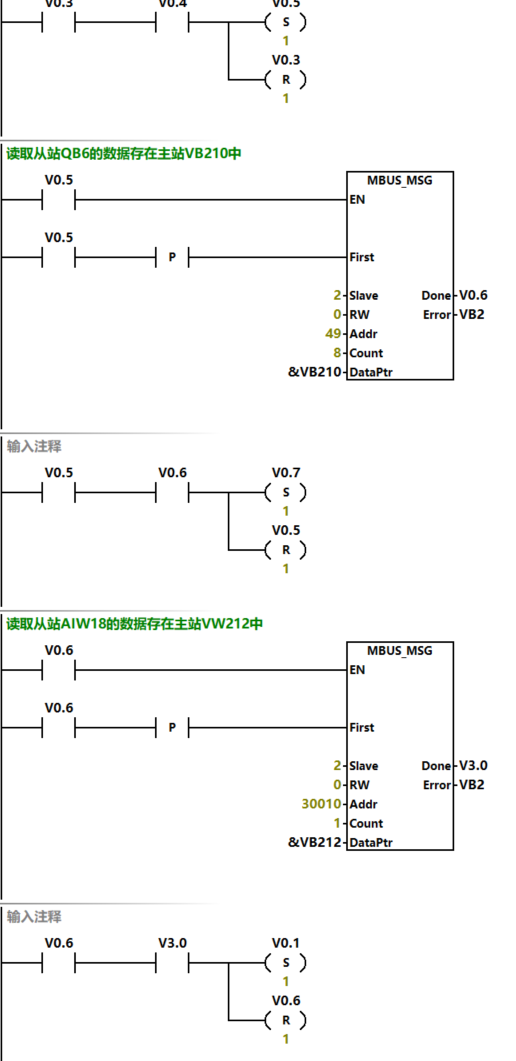
Figure 7: Master Station Data Read/Write Program
2. After completing the communication program, 286 V storage areas need to be allocated for internal calculations, as shown in Figure 8.
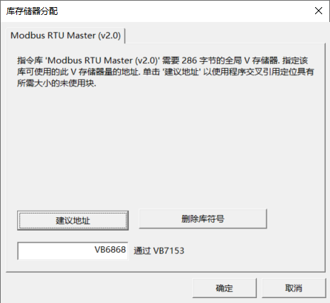
Figure 8: Allocating Storage
3. After downloading the program for testing, one end of the hardware USB from Figure 2 should be plugged into the computer, and the RS485 male connector should be plugged into the CPU body serial port. After plugging in, check the specific COM port in the computer manager.
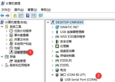
Figure 9: View Port Number
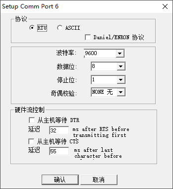
4. Open the Modsim32 debugging software, select the port matching Figure 9 in the connection settings, as shown in Figure 10; after selecting the connection port, a protocol parameter setting dialog box will pop up, as shown in Figure 11. It is important to ensure that the communication parameters are consistent with the initialization command parameters.
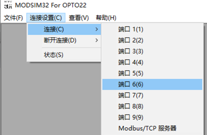 Figure 10: Connection Settings
5. In the “File” menu of Figure 10, select New, where device ID represents the slave address, set to 2.
The first group of data reads 5 consecutive words starting from slave 40001 (VW300-VW308) and places them in the master station starting from VW200. In the debugging software, write data into the 5 consecutive words starting from 40001, then monitor the data from VW200-VW208 on the 200SMART side, which should be the same, as shown in Figure 12.
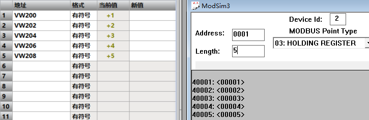
Figure 12: Data Exchange
The second group of data writes the status of 8 consecutive bits from the master station I0.0 to the slave Q0.0. When forcing I0.2 and I0.4, the status of the slave 0003 0005 is 1; as shown in Figure 13.
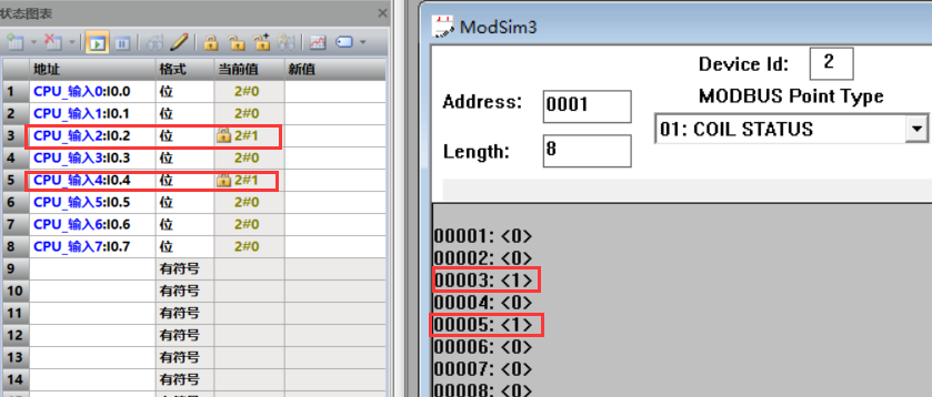
Figure 13: Data Exchange
The third group reads the data from the slave QB6 into the master station VB210. In the debugging software, set Q6.0 and Q6.1 to 1, and the data on the SMART side VB210 is 3, as shown in Figure 14.
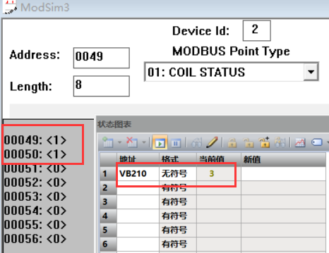
Figure 14: Data Exchange
The fourth group reads the data from the slave AIW18 into the master station VW212. After setting 30010 to 457 in the debugging software, the data on the SMART side VW212 is 457, as shown in Figure 15.
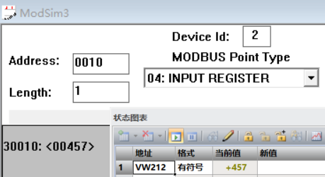
Figure 15: Data Exchange
Source: Jicheng Training Network, Author: Sui Xiangjian, Reproduction without permission is prohibited~