The CAN bus was born at the renowned Bosch company in Germany, arising alongside the development of the automotive industry. In the 1970s and 1980s, the automotive industry was booming, but several serious problems emerged:
|
1 |
There was no communication protocol in cars, making it difficult to support interaction between multiple controllers. Imagine trying to communicate between multiple microcontrollers without a protocol; it would be quite troublesome, right? This led to a limited number of controllers in vehicles, and the wiring harnesses were generally long and bulky, resulting in high costs and inconvenient assembly, with obvious drawbacks. |
|
2 |
The anti-interference capability was very poor. Digital signals were acceptable, but analog signals transmitted over long wiring harnesses were prone to errors. |
|
3 |
When multiple controllers collected the same signal, circuit matching became very challenging, as it would affect the input resistance. |
|
…… |
Thus, the Germans came up with a solution.
In 1986, Bosch proposed the CAN bus standard at the SAE conference, followed by Intel and Philips releasing CAN controller chips the next year. Since then, the CAN bus has embarked on a glorious history in automotive communication, and to this day, no communication protocol has been able to shake its status.
How does the CAN bus address the several drawbacks mentioned above by the first speaker?
|
1 |
There is now a communication protocol between controllers, making interaction easier, allowing multiple controllers to be installed in the vehicle, enabling distributed control, and shortening the signal wiring harness. |
|
2 |
The CAN bus has very strong anti-interference capabilities. |
|
3 |
Only one controller needs to collect the signal, which can then be broadcast to the necessary modules via CAN, eliminating impedance matching issues. |
|
…… |
Since the advent of the CAN bus, the electronic control system of the entire vehicle can be designed in a coordinated manner, making “functional interaction” a very important topic, leading to the emergence of the concept of “functional architecture design“.
In the field of architecture design, there are several specialized tools, such as Vector’s Preevision, Sweden’s Systemweaver, Siemens’ Polarion, and IBM’s DOORS, among others. Their common feature is that they are very powerful, so powerful that they can do everything, except for basic interaction descriptions and protocols such as DBC, they can even handle wiring harness lengths and weight specifications. With such tools, many positions in an automotive company can be eliminated, as almost all work can be done within them (of course, this also means that architectural work becomes quite burdensome).
The first speaker holds a reserved attitude towards this, having observed that the vast majority of companies’ architectural development tools are superficial, merely decorative, used by only one or two people, and fail to achieve the effects of brainstorming and collaborative design.
The first speaker believes that such comprehensive and omnipotent architecture work is more inclined towards coordination and organization, suitable for traditional automotive functional architecture design that is already close to standardization, such as fuel vehicles, buses, and trucks.
For rapidly developing new technologies, such as new energy and intelligent driving, these tools struggle significantly, as these new technologies are still in a state of continuous change and improvement, especially since many details still require scrutiny and optimization, which architecture engineers may not be particularly familiar with, rendering them of little practical value. As for using these relatively expensive tools for wiring harness weight simulation, the first speaker finds it impractical, as wiring harness engineers already have better and cheaper tools and methods.
Functional architecture work should focus on macro control rather than micro design; overly micro design can limit the creativity of component engineers. Functional architecture work should fully leverage the expertise of various professionals, with the architecture centrally controlling the overall process. Only in this way can multiple departments work together effectively, maximizing talents from all sides to produce better vehicles.
The core of architectural work should be the design of the CAN backbone network, tracking which sensors and actuators in the vehicle collect, control, and complete which functions through the CAN backbone network. Unfortunately, after more than 30 years, some automotive companies have managed to turn Bosch’s great invention into a tedious, error-prone, and growth-limited physical labor, with bus engineers working tirelessly while controller engineers are unable to fully utilize their talents…

In light of this, we have specially invited the team from the Innovation Electronics Laboratory at Jiaotong University in Shanghai, whofocus on the design of the entire vehicle’s CAN backbone network and functional architecture, and have already made a series of breakthrough advancements.
Next, we will introduce their latest concepts and developments in this field, as well as how they use the CAN backbone network as a carrier to create electronic control functional structures and functional interactions; how they leverage innovative methods and tools to greatly assist both bus engineers and controller engineers, ultimately enhancing the design quality of the entire vehicle.
The team’s open-source solution adopts a “server-client” design model, with the server installed on a PC and the client installed on various controller engineers’ computers. Its working principle simulates the communication and thought processes between engineers in real-world work, and programmatically, standardizes and formats all of this.
On the client side, based on specific permissions (permission configuration is one of its significant features, ensuring sufficient access without being excessive), each component can view the signals on its network or the entire vehicle’s signals, can upload messages (in specific operations, the uploaded ID must be within a preset ID range, and the total load rate cannot exceed a certain set value), can delete messages and signals, and can evaluate signals sent by other components, locking their reception. Once locked, the sender cannot modify it, but can be unlocked if necessary.
The client can graphically view the layout of message signals, verify whether the signal arrangement is reasonable, and component engineers can independently arrange signal positions and group real-time signals with similar timing into one message.
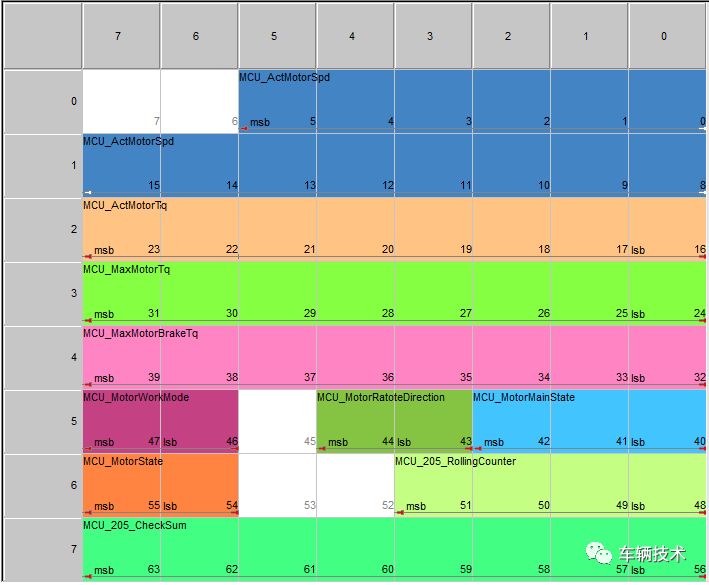
The client can independently export its related Excel-formatted CAN protocols; from this perspective, the content of the Excel protocol exported by each client is unique.
According to further understanding, the overall method of using this system is “offline communication, online submission, with bus engineers centrally controlling”. “Offline communication” is necessary, as it is closely related to functional discussion and review. Each component engineer independently communicates the signals required for functionality, who will send them, and then locks them in the system through the client. They can also propose signals they wish to send for review and evaluation by other components.
“The central control by bus engineers” means that the system has an “application mode”; compared to the “free mode”, all operations performed in the client under the application mode require approval from the bus engineer on the server side to take effect, suitable for the fine-tuning and optimization design phase of the CAN backbone bus.
The first speaker highly agrees with this method and concept, as it is undoubtedly a revolutionary method or tool that thoroughly addresses the chaos, fragmentation, and errors in the design process of vehicle networks and functional architecture, significantly enhancing the control capabilities of automotive companies over networks and architectures.
This method enhances the bus engineer’s control over the backbone bus and functional architecture while liberating them from the detailed definition of signals, allowing them to focus on more meaningful macro designs, such as overall functional architecture, research on new communication technologies, communication quality analysis and optimization, and other more specialized tasks. At the same time, it fully leverages the intelligence and initiative of various component engineers regarding signal details, which is very beneficial for achieving a 100% accurate and scientifically reasonable CAN network.

Regarding the server side, the management authority belongs to the bus engineer, and the numerous configurations and settings made by the bus engineer on the server determine the operating permissions of each client. The bus engineer also holds the highest decision-making power in the entire system.
It is understood that it can support multiple projects being developed simultaneously, can reuse already developed CAN networks, can generate DBC files in batch with one click (which is impressive), and can use super administrator privileges to fine-tune the bus (such as modifying ID, cycle, etc.), and can export the entire vehicle’s CAN protocol, etc.
The first speaker learned that the team is currently working on a free “Super Network” initiative, which has already deployed the system on a public server; users only need to install a client to use it, and some users are already experiencing it.The server side must be deployed on a computer within the company’s local area network and managed by the bus engineer during actual user experience.
Bus engineers or controller engineers can use the client to play the role of one of the components, experiencing the convenience and efficiency it brings, as well as its powerful collaborative design capabilities. The first speaker looked at it and found the signal content quite interesting, such as “the color of the rabbit, red, orange, blue, black” and “the speed of the leopard running, km/h”; of course, there are also some serious signals, such as “motor speed”, etc. These are not related to design secrets; the focus is to let peers experience how it ensures that CAN bus design is seamless and 100% error-free, and how it enhances the capabilities of clients and convenience.
The initial plan is to design synchronously 20 projects, each with 3-4 CAN segments, with each segment containing about 10 controllers. The topology will be published, and the method of “offline communication” will be announced separately; DBC conversion will also be carried out periodically as needed.

The first speaker is hereby initiating a registration experience activity, which only requires leaving a message in the background with your name (a nickname is fine) and company name, and indicating whether you are a controller engineer or a bus engineer (bus engineers will be prioritized for the “gateway” role).
Friends who register successfully will receive a client installation package and a user guide, and you can start experiencing it.
Subsequently, based on the registration situation, the team will publish some common explanations and materials, as well as necessary supplements (still published on this public account).
After the first experience of this design method and concept, the first speaker felt very excited, it is more focused and convenient than tools like PREEvision, and indeed ensures that bus design work is 100% error-free, allowing bus engineers to escape from the low-efficiency repetitive task of editing Excel, concentrating their attention on more important and meaningful work. Meanwhile, controller engineers also have more room to define signals, making signal definitions more reasonable and accurate, and the protocols exported by each controller engineer contain only the parts relevant to them, which can be directly sent to suppliers.
The highest administrative authority of this system lies with the bus engineer, and the permissions regarding which IDs each controller can send, which segments they can operate, how much load rate they can occupy, whether they are allowed to view the entire network, and whether they can export protocols, etc., are all set by the bus engineer. This undoubtedly reduces the repetitive workload of the bus engineer while greatly enhancing their macro control capability over bus design work.
According to actual user feedback, the system’s DBC batch conversion function is the best and most mature DBC conversion tool the first speaker has ever seen, with no errors at all. It fully leverages the advantages of both Excel files and DBC files, proving particularly useful for our reviews, releases, software development, and testing tools.
The first speaker also inquired about costs; it is understood that the trial experience is free forever, and the commercial deployment policy is currently around several thousand yuan, with no limit on the number of clients.
Hurry up and share, let’s experience it together~