Introduction: In previous videos, we introduced the ROLL mode in the horizontal time base. Now, let’s take a look at the X-Y mode in the horizontal time base. What exactly is it?
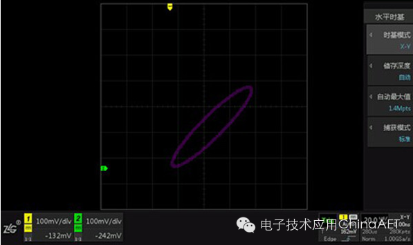
Figure 1 Oscilloscope Screen Display in X-Y Mode
In simple terms, the X-Y mode converts voltage-time display into voltage-voltage display. In fact, in the ZDS2022 oscilloscope, the Y-axis variable input from channel CH1 is converted into the X-axis variable in X-Y mode. Therefore, the amplitude of channel 1 is plotted on the X-axis, and the amplitude of channel 2 is plotted on the Y-axis, as shown in Figure 2. When this mode is enabled, the oscilloscope operates with two channels fixed.
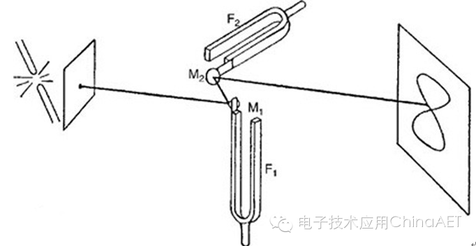
Figure 2 Lissajous Figure Origin Diagram
In X-Y mode, we often use the Lissajous method for relevant measurements. Here, I would like to share a little story about the Lissajous method. About 200 years ago, a French mathematician named Lissajous invented a device that reflected a beam of light off a mirror fixed to a tuning fork, which was then reflected off a second mirror also fixed to a tuning fork. The two tuning forks vibrated in perpendicular directions, and their pitches were often set differently to achieve different resonant frequencies. The light beam finally hit the wall, forming a pattern, as shown in Figure 2. This pattern is known as a Lissajous figure. This invention laid the foundation for many instruments, such as resonant recorders.
So, how do we use the Lissajous method for measurements in the oscilloscope’s X-Y horizontal time base mode? The next video will explain this in detail. Stay tuned.