Click the blue text above Tan Si Laboratory
to get more information on automotive cybersecurity

01
What is a Watchdog?
The watchdog technology was first proposed by AMD, a U.S. semiconductor giant, in the 1980s. It is a technology specifically designed to detect and record the operational status of processors and reset them in case of anomalies. With continuous iterations in technology, watchdogs have gradually evolved into specialized chips widely used in automotive, industrial automation, IoT, and other fields.

This dog is not that dog!!!
Software will perform a dog feeding operation after executing specific instructions. If the watchdog does not receive a signal from the software within a certain period, it assumes a system failure and enters the interrupt handler or forces a system reset. After powering on, the watchdog can be enabled based on different operating modes. If enabled, the counter begins counting. If the watchdog is not fed in the set time, a watchdog timeout occurs. The watchdog is configured through registers, counting the dog barking time, and the barking module determines the interrupt or reset method issued after a watchdog timeout.
As watchdog technology has developed, its functions have become more comprehensive, leading to many detailed classifications from different perspectives. For example, they can be classified into hardware watchdogs and software watchdogs; based on integration with microcontrollers, they can be divided into internal watchdogs and external watchdogs.
02
Integrated Watchdog in TLF35584
Taking Infineon’s TLF35584 chip, the most commonly used power management chip in automotive products, as an example, this chip has passed the ISO26262 ASILD certification and integrates a watchdog module. This watchdog module belongs to both hardware and external watchdogs, consisting of Window Watchdog and Functional Watchdog (referred to as WWD and FWD hereafter).
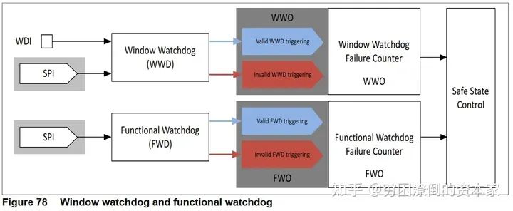
Window Watchdog and Functional Watchdog
-
The functional watchdog and window watchdog operate independently and are completely separate.
-
Functional and window watchdogs can be activated and deactivated independently.
-
The results of the watchdog (valid or invalid trigger) are monitored independently by their respective watchdog fault counters.
-
The state of the window watchdog is WWO, which can be “valid WWD trigger” or “invalid WWD trigger”.
-
The state of the functional watchdog is FWO, which can be “valid FWD trigger” or “invalid FWD trigger”.
-
The impact of the settings of both watchdogs on safety state control is described in the chapter on safety state control for better understanding.
03
Window Watchdog (WWD)
We refer to it as a window watchdog or time watchdog. The monitored controller (MCU) must trigger (feed the dog) within the Open Window period. Feeding can be done via a falling edge on the WDI pin or by writing to the WWDSCMD register via SPI commands, depending on the configuration. Once triggered, the “Open Window” ends. The watchdog output indicates the “valid” or “invalid” WWD trigger of the WWD fault counter.
If triggered validly, the “Closed Window” starts. If no trigger occurs during the “Open Window” or a trigger occurs during the “Closed Window”, the watchdog output indicates an “invalid WWD trigger” to the WWD fault counter and starts a new “Open Window”.
1. WWD Working State Diagram
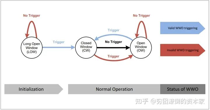
Window Watchdog State
-
“Trigger” can be a SPI command sent to the WWDSCMD register or a valid watchdog trigger on the WDI pin.
-
In a “Long Open Window”, “No Trigger” is considered an “invalid WWD trigger”, and the watchdog will open a new “Long Open Window”.
-
In a “Long Open Window”, a “Trigger” is considered a “valid WWD trigger”, the watchdog closes the “Long Open Window” and opens the “Closed Window”.
-
In a “Closed Window”, a “Trigger” is considered an “invalid WWD trigger”.
-
After the “Closed Window” ends, “No Trigger” in the “Closed Window” will move the watchdog to the “Open Window”.
-
In the “Open Window”, a “Trigger” is considered a “valid WWD trigger”, the watchdog closes the “Open Window” and opens the “Closed Window”.
-
In the “Open Window”, “No Trigger” is considered an “invalid WWD trigger”.
2. WDI Pin Triggering WWD
The watchdog input pin WDI has an integrated pull-down current IWDI. The watchdog input WDI can be converted to a high level during the “Closed Window” or in the subsequent “Open Window”.
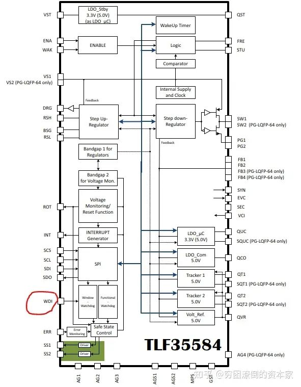
WDI Pin
-
Valid Trigger Signal of WD
The watchdog input WDI is sampled periodically at the TSAMT cycle. The valid trigger signal is the falling edge from VWDIV high to VWDIV low. To improve the noise or glitch immunity on the WDI input, the valid trigger signal requires at least two high samples followed by two low samples, considering the second continuous low sampling point of the low signal as a valid trigger. For instance, if the first three samples of the trigger pulse at the WDI pin (two highs and one low) occur within the “Closed Window”, and only the fourth sample (the second low sample) is collected in the “Open Window”, the watchdog output WWO will indicate a “valid WWD trigger”.
-
Invalid WDI Trigger
No trigger signal detected during the “Open Window” or detecting a trigger signal during the “Closed Window” is considered an invalid trigger. The watchdog output WDO immediately indicates “invalid trigger” after no valid trigger during the “Open Window” or immediately indicates “invalid trigger” after detecting a trigger signal during the “Closed Window”.
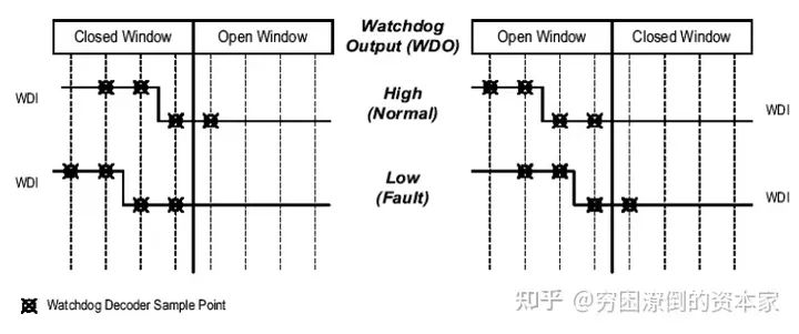
WDI Valid and Invalid Trigger
3. WWD Normal Operation – Correct Trigger
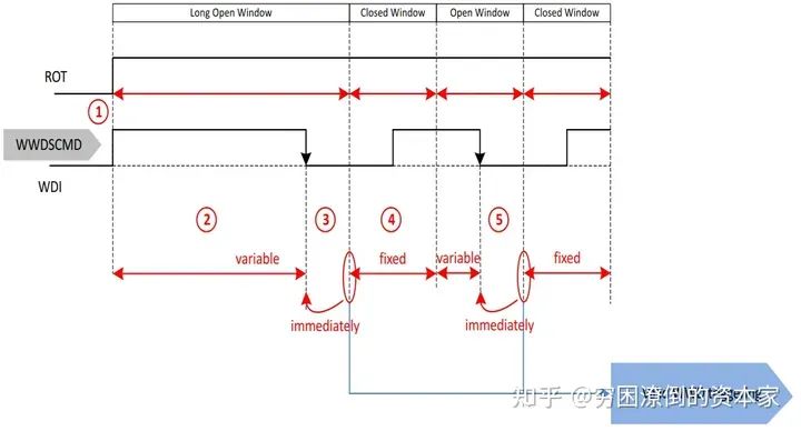
Correct Trigger
-
If the reset output of ROT (related voltage of the monitored microcontroller) goes high, the “Long Open Window” starts in the INIT state. If the window watchdog is disabled in sleep mode, the first Open Window will transition from sleep mode to wake mode (indicated by an interrupt). The time of the first Open Window depends on the configured cycle time, either 600 ms (WDCYC = 1) or 60 ms (WDCYC = 0).
-
During the “Long Open Window”, it is expected to select valid triggering WWD based on the configured trigger. The maximum duration of the “Long Open Window” is fixed, but it will terminate once a “valid WWD trigger” is recognized.
-
The window watchdog will now enter the “Closed Window”. Upon receiving the first valid trigger, the device will be allowed to transition from INIT state to NORMAL state or from WAKE state to NORMAL state.
-
The “Closed Window” has a fixed duration tWD,CW (which can be determined by SPI commands). It starts immediately after a valid trigger signal, closing the “Open Window” or “Long Open Window”. No trigger signals should be applied during the “Closed Window”. The transition from low to high on the WDI pin will not be detected and will not cause a trigger event.
-
A valid trigger signal immediately terminates the “Open Window”, so the duration of the “Open Window” is variable and depends on when the microcontroller arranges for the trigger. This is regarded as a “valid WWD trigger”.
4. WWD Abnormal Operation – No Trigger in Long Open Window
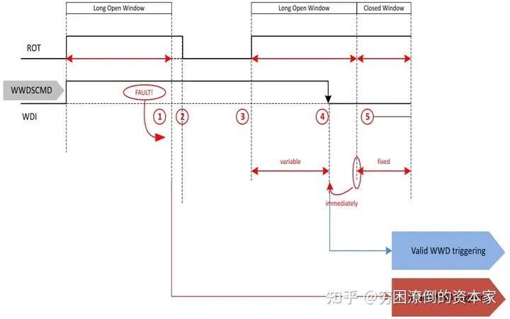
No Trigger in Long Open Window
-
The initialization timeout and Long Open Window (LOW) have the same typical value. This typically results in the initialization timeout completing before or simultaneously with the low level, skipping the interrupt event (1). Although due to given precision, missing a valid trigger within the “Long Open Window” may lead to an interrupt event after the low level ends, increasing the window watchdog fault counter by 2.
-
The INIT state timer times out for the first time. Since a valid trigger from the window watchdog was not received as expected during the INIT state, a so-called “soft reset” will occur: pin ROT goes to zero, but the output voltage of the post-regulator remains on. Additional information: If the window watchdog is not correctly triggered in the next “Long Open Window” during the subsequent INIT phase, a “hard reset” will occur, meaning pin ROT will go to zero, and the output voltage will also be turned off. After the third invalid trigger during the INIT phase, the device will enter the FAILSAFE state.
-
After the power-up reset delay time trd, the so-called “soft reset” pin ROT goes high again, allowing the watchdog to open a “Long Open Window” to give the microcontroller a chance to trigger and synchronize to the watchdog cycle.
-
A valid trigger terminates the “Long Open Window”, making its duration variable and dependent on the trigger. This is regarded as a “valid WWD trigger” and starts the “Closed Window”. Without issuing an interrupt, the window watchdog fault counter will decrease by 1.
-
The subsequent “Closed Window” duration tWD,CW. During this time, triggers will be considered “invalid WWD triggers”.
5. WWD Abnormal Operation – No Trigger in Open Window
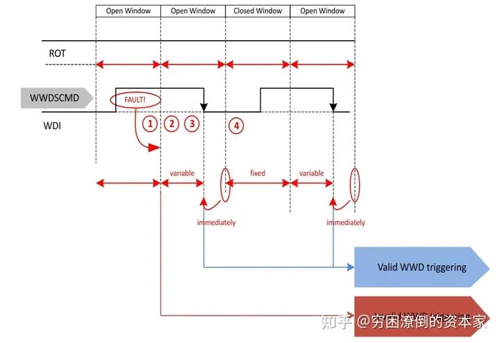
No Trigger in Open Window
-
Missing a valid trigger within the “Open Window” results in an “invalid WWD trigger” after the window ends. This event is indicated by an interrupt, increasing the window watchdog fault counter by 2.
-
After detecting an “invalid WWD trigger”, the watchdog will initiate a new “Open Window” lasting for tWD,CW, allowing the microcontroller a chance to trigger and synchronize to the watchdog cycle.
-
A valid trigger terminates the “Open Window”, making its duration variable and dependent on the trigger. This is regarded as a “valid WWD trigger” and starts the “Closed Window”. Without issuing an interrupt, the window watchdog fault counter will decrease by 1.
-
If multiple “invalid WWD triggers” occur within the “Open Window”, the window watchdog fault counter will increase by 2 again until reaching the configured threshold. In this case, a reset command will be issued.
-
The subsequent “Closed Window” duration tWD,CW. During this time, triggers will be considered “invalid WWD triggers”.
The behavior of pin ROT depends on the value of ΣWWO. In the above example, it is assumed that invalid triggers do not exceed the threshold ΣWWO.
6. WWD Abnormal Operation – Incorrect Trigger in Closed Window After Initialization
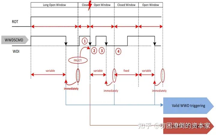
-
Triggering during the “Closed Window” is indicated as an “invalid WWD trigger”. This event is indicated by an interrupt, and the window watchdog fault counter increases by 2.
-
The “Closed Window” will close due to the “invalid WWD trigger”. Initially, it will last for tWD,CW. An erroneous trigger terminates the “Closed Window” and starts the “Open Window”, allowing the microprocessor a chance to synchronize to the window watchdog cycle.
-
In this “Open Window”, a valid trigger is expected to occur. A valid trigger will terminate the “Open Window”, making its duration variable and dependent on the trigger. This is regarded as a “valid WWD trigger” and starts the “Closed Window”. Without issuing an interrupt, the window watchdog fault counter will decrease by 1.
-
The subsequent “Closed Window” duration tWD,CW. During this time, triggers will be considered “invalid WWD triggers”.
The behavior of pin ROT depends on the value of ΣWWO. In the above example, it is assumed that invalid triggers do not exceed the threshold ΣWWO.
7. WWD Abnormal Operation – Incorrect Trigger in Steady State “Closed Window”
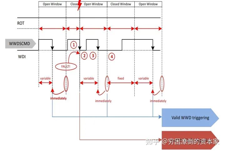
Incorrect Trigger in Closed Window
-
Triggering during the “Closed Window” is indicated as an “invalid WWD trigger”. This event is indicated by an interrupt, and the window watchdog fault counter increases by 2.
-
The “Closed Window” will close due to the “invalid WWD trigger”. Initially, it will last for tWD,CW. An erroneous trigger terminates the “Closed Window” and starts the “Open Window”, allowing the microprocessor a chance to synchronize to the window watchdog cycle.
-
In this “Open Window”, a valid trigger is expected to occur. A valid trigger will terminate the “Open Window”, making its duration variable and dependent on the trigger. This is regarded as a “valid WWD trigger” and starts the “Closed Window”. Without issuing an interrupt, the window watchdog fault counter will decrease by 1.
-
The subsequent “Closed Window” duration tWD,CW. During this time, triggers will be considered “invalid WWD triggers”.
-
The behavior of pin ROT depends on the value of ΣWWO. In the above example, it is assumed that invalid triggers do not exceed the threshold ΣWWO.
04
Functional Watchdog (FWD)
We refer to it as a functional watchdog or question-answer watchdog. In a stable state, a question is generated (taken from a table), while the heartbeat counter starts counting from zero. The heartbeat counter starts counting until the heartbeat period ends. The duration of the heartbeat period can be set and adjusted via SPI commands.
The question consists of 4 bits, and the expected answer consists of 4 replies, each 8 bits. These four replies should be sent before the heartbeat period ends. The last reply should be written to the synchronization reply register to reset the heartbeat counter.
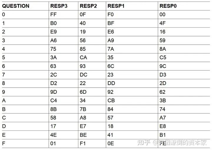
Functional Watchdog Questions and Replies
The functional watchdog output FWO is an internal signal: it connects to the FWD fault counter. The value of the functional watchdog FWO output is either “valid FWD trigger” or “invalid FWD trigger”.
1. FWD Workflow Diagram
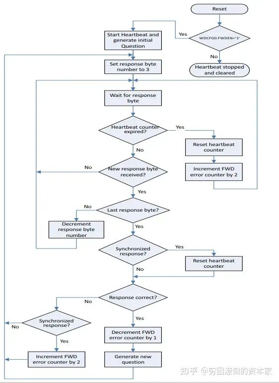
FWD Workflow Diagram
The steps are as follows:
-
First, determine whether FWD is enabled; if not enabled, stop and clear the heartbeat counter value; if enabled, proceed to step 2;
-
Activate the heartbeat counter and generate the initialization question;
-
Set the response byte number to 3, preparing to receive the first reply;
-
Wait for the reply value;
-
Determine whether the heartbeat counter has timed out. If it times out, reset the heartbeat counter, and add 2 to the FWD fault counter, then proceed to step 4; if it has not timed out, proceed to step 6;
-
Determine whether a new reply value has been received. If not received, proceed to step 4; if received, proceed to step 7;
-
Determine whether it is the last reply. If not, reduce the response byte number by 1 and proceed to step 4; if it is, proceed to step 8;
-
Determine whether the reply is synchronized. If not synchronized, proceed to step 9; if synchronized, reset the heartbeat counter and also proceed to step 9;
-
Determine whether the reply is correct. If not correct, proceed to step 10; if correct, decrease the FWD fault counter by 1 and generate a new question, then proceed to step 3;
-
Determine whether the reply is synchronized. If not synchronized, proceed to step 3; if synchronized, add 2 to the FWD fault counter and also proceed to step 3.
2. FWD Normal Operation – Correct Trigger
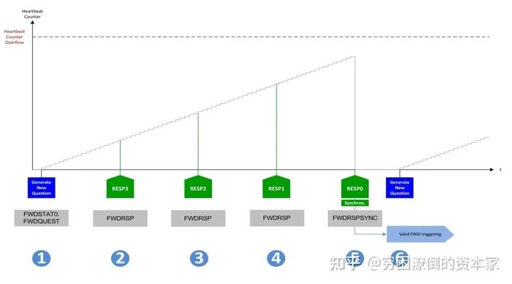
Correct Trigger Mode
The steps are as follows:
-
Generate a new question while the heartbeat counter starts counting (assuming a previous “valid FWD trigger” occurred)
-
Receive the correct reply (RESP3)
-
Receive the correct reply (RESP2)
-
Receive the correct reply (RESP1)
-
Receive the correct synchronization reply (RESP0). All replies are correct, the order of replies is correct, and the last synchronized reply is received before the heartbeat counter overflows. The heartbeat counter will be reset (set to zero). This is regarded as a “valid FWD trigger”, and the functional watchdog error counter ΣFWO decreases by 1 (if the functional watchdog error counter value is greater than zero)
-
Generate a new question while the heartbeat counter starts counting
3. FWD Abnormal Operation – Synchronization Loss
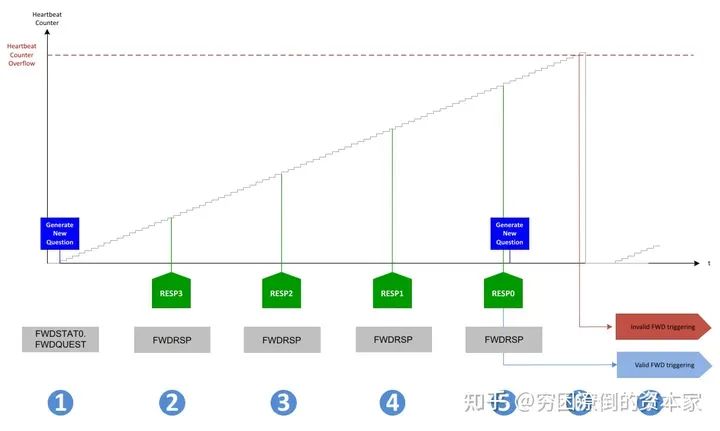
Synchronization Loss
The steps are as follows:
-
Generate a new question while the heartbeat counter starts counting (assuming a previous “valid FWD trigger” occurred)
-
Receive the correct reply (RESP3)
-
Receive the correct reply (RESP2)
-
Receive the correct reply (RESP1)
-
Receive the correct reply (RESP0), but not synchronized (writing to the wrong register). Up to this point, all replies are correct, and the order of replies is correct, and the last reply is received before the heartbeat counter overflows. The heartbeat counter will not be reset and continues counting. This is regarded as a “valid FWD trigger”, and the functional watchdog error counter ΣFWO increases by 2. The heartbeat counter resets.
-
The heartbeat counter starts counting, but no new question is generated.
4. FWD Abnormal Operation – Incorrect Reply
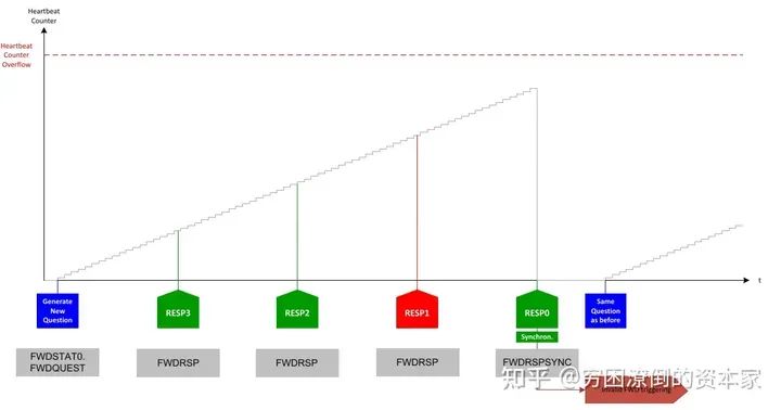
Incorrect Reply
The steps are as follows:
-
Generate a new question while the heartbeat counter starts counting (assuming a previous “valid FWD trigger” occurred)
-
Receive the correct reply (RESP3)
-
Receive the correct reply (RESP2)
-
Receive an incorrect reply (RESP1)
-
Receive the correct reply (RESP0), but the complete answer is incorrect. This is regarded as an “invalid FWD trigger”. The functional watchdog error counter ΣFWO increases by 2. The heartbeat counter resets.
-
No new question is generated, but the heartbeat counter starts counting.
Note: If Resp2 and Resp1 are mixed, treating both replies as incorrect, they must be sent in the correct order.
5. FWD Abnormal Operation – Reply Loss
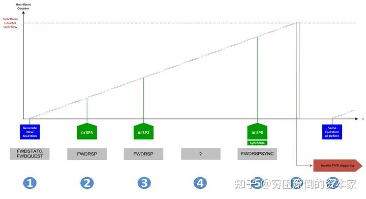
Reply Loss
The steps are as follows:
-
Generate a new question while the heartbeat counter starts counting (assuming a previous “valid FWD trigger” occurred)
-
Receive the correct reply (RESP3)
-
Receive the correct reply (RESP2)
-
Missing reply (RESP1)
-
Receive the correct reply (RESP0). Therefore, due to the missing reply (in this example, RESP1), the last reply is not the last reply but the second to last reply. The functional watchdog will wait for all four replies to be written, while the heartbeat counter continues counting. All four replies do not have a fixed time but must be sent in the correct order before the heartbeat counter expires.
-
Due to the missing reply RESP1, the complete answer is incorrect. Although the last reply is synchronized, the heartbeat counter will not be reset and continues counting until overflow occurs. This is regarded as an “invalid FWD trigger”. The functional watchdog error counter ΣFWO increases by 2. The heartbeat counter resets.
-
No new question is generated, and the heartbeat counter starts counting.
05
Why Do We Need a Watchdog?
1. Functional Safety Standard Software Requirements
First, in Chapter 6 of the functional safety standard, section 7.4.12 mentions that watchdogs should be used for time monitoring of software and program flow monitoring.
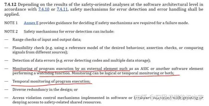
ISO26262 Standard Chapter 6
2. Functional Safety Standard Hardware Requirements
Appendix in Chapter 5 also mentions the functions and diagnostic coverage of different watchdogs.
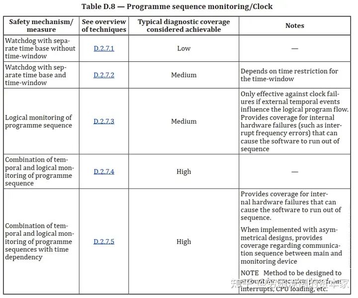
Diagnostic Coverage of Watchdogs
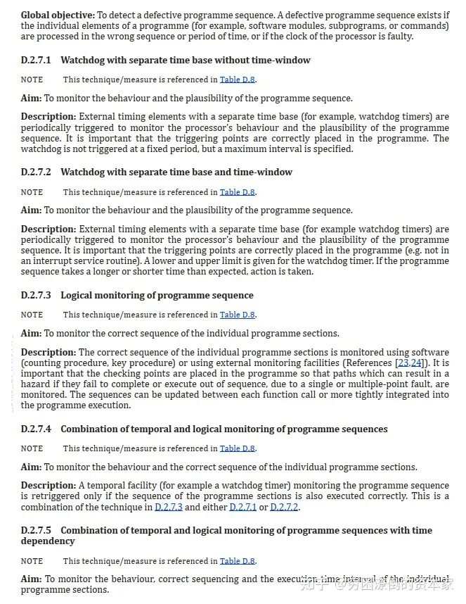
Functional Safety Standards
The standard introduces several watchdogs’ objectives and functional descriptions. I will summarize some usages and requirements of watchdogs as safety mechanisms in ISO26262.
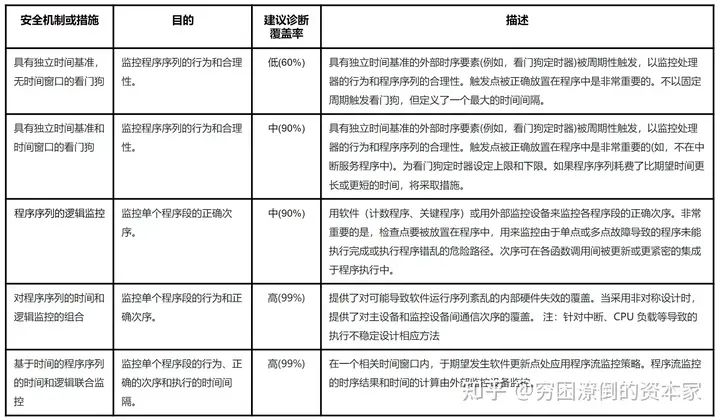
Role of Watchdogs
06
How to Use a Watchdog?
1. Functional Safety Requirements for Watchdogs
The standard does not explicitly state how different ASIL levels should use watchdogs. Below are some suggestions based on my project experience, for reference only.
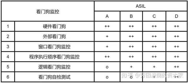
Suggestions for Using Watchdog Monitoring
2. Internal Watchdog VS External Watchdog

Internal Watchdog vs External Watchdog
3. Role of Watchdog Monitoring Mechanism

Watchdog Monitoring Mechanism
07
Watchdog Autosar Architecture
1. Static Architecture
First, let’s look at the static architecture of the watchdog function in Autosar. The watchdog is a very standard function in Autosar, and the architecture is quite clear.
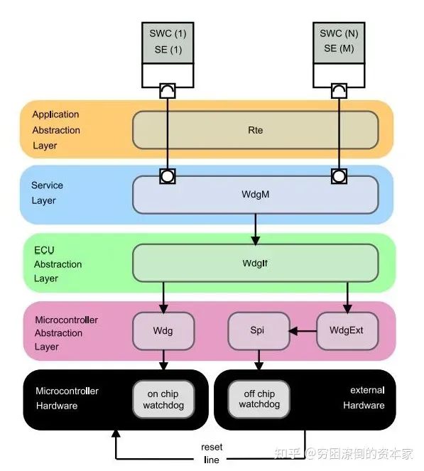
Static Architecture of Autosar Watchdog
The watchdog structure in Autosar mainly includes:
Internal Watchdog: WatchDog Manager, WatchDog Interface, WatchDog Driver, On Chip WatchDog
External Watchdog: WatchDog Manager, WatchDog Interface, SPI, Off Chip WatchDog
Corresponding to the service layer, ECU abstraction layer, controller abstraction layer (MCAL), and hardware in Autosar
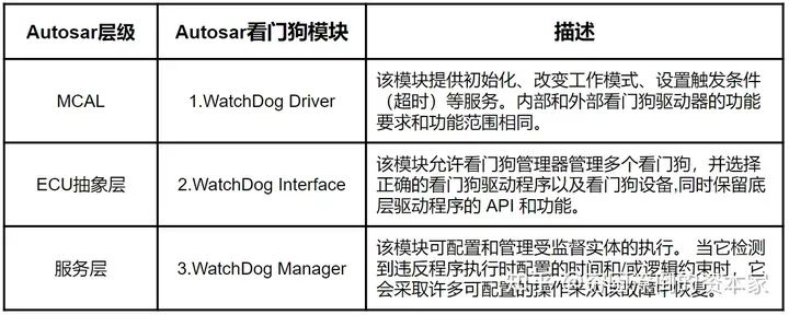
Autosar Watchdog Module
It is worth noting that the internal watchdog can be accessed through the WatchDog Driver, which is relatively simple; while the external watchdog requires using SPI communication or other methods for access, which is slightly more complex than the internal watchdog.
Supervised Entity: This is the object you want to monitor, which can be a SWC, runtime entity, BSW module, or complex driver.
Check Point: Important positions inserted in the supervised entity are called checkpoints, and all subsequent calculations and checks are based on these checkpoints.
2. Dynamic Architecture
The following diagram shows three types of function call scenarios for initializing the watchdog, triggering the watchdog feeding, and changing the watchdog mode.
-
Watchdog Initialization: The watchdog initialization configuration is completed by calling the function Wdg_Init through the EcuM module;
-
Triggering the Watchdog Feeding: The feeding action is triggered by calling the function WdgIf_SetTriggerCondition provided by the WdgIf module through the WdgM module;
-
Changing the Watchdog Mode: The watchdog mode is changed by calling the function WdgIf_SetMode provided by the WdgM module.
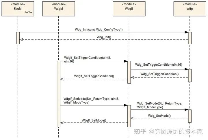
Watchdog Feeding Process 1
The following diagram shows the timing diagram for the interaction between the Watchdog driver and the underlying watchdog hardware. It can be seen that WdgIf_SetTriggerCondition will continue to call the function Wdg_SetTriggerCondition in the Wdg driver to implement the feeding action.
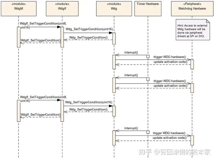
Watchdog Feeding Process 2
08
WatchDog Driver
This module provides functionalities such as initializing the hardware watchdog, changing operation modes, and setting the trigger method for feeding the watchdog. Additionally, regardless of whether the watchdog is internal or external, the API for the watchdog driver should always remain consistent. However, for the internal watchdog, its driver belongs to the MCAL layer, while for the external watchdog, it belongs to the ECU hardware abstraction layer. This external watchdog driver needs to call other drivers in MCAL to implement the feeding action, such as GPIO, IIC, or SPI drivers.
Taking Infineon’s TLF35584 as an example, SPI drivers are required.
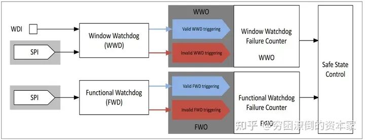
Block Diagram of TLF35584 Chip’s Watchdog System
In the AUTOSAR architecture, for the Watchdog Driver, three control modes for the watchdog are defined as follows:
-
Off Mode: Indicates the watchdog is off; for critical safety systems, it generally cannot be switched to off state. Once turned on, it cannot be turned off;
-
Slow Mode: Indicates a long feeding window for the watchdog; this mode is generally used during system startup initialization;
-
Fast Mode: Indicates the normal feeding window mode of the watchdog; this mode is used during normal system operation.
09
WatchDog Interface
The Watchdog If module, fully named the Watchdog Interface, serves as an abstraction of the underlying Watchdog Driver to achieve decoupling between the underlying hardware and software.
This module’s basic function is merely to serve as an abstraction layer for the underlying watchdog driver to interact with the upper-level watchdog management module. The characteristics of the underlying watchdog driver, such as window control and time cycle settings, cannot be accomplished through the Watchdog If module.
If more than one watchdog driver is managed by the upper-level Watchdog Manager, the DeviceIndex will need to be checked, and if an error occurs, it needs to be reported promptly.
Overall, the configuration of the Watchdog If module is relatively simple.
Functions:
-
WdgIf_SetMode: Set the watchdog mode
-
WdgIf_SetTriggerCondition: Trigger the feeding operation
-
WdgIf_GetVersionInfo: Get the Autosar version information of the watchdog module
Parameters:
-
WdgIfVersionInfoApi: Whether to enable the Autosar version reading function
-
WdgIfDevErrorDetect: Whether to enable module error detection function TRUE for enable, FALSE for disable
-
WdgIfDeviceIndex: Index supporting multiple watchdog drivers
-
WdgIfDriverRef: Current watchdog index
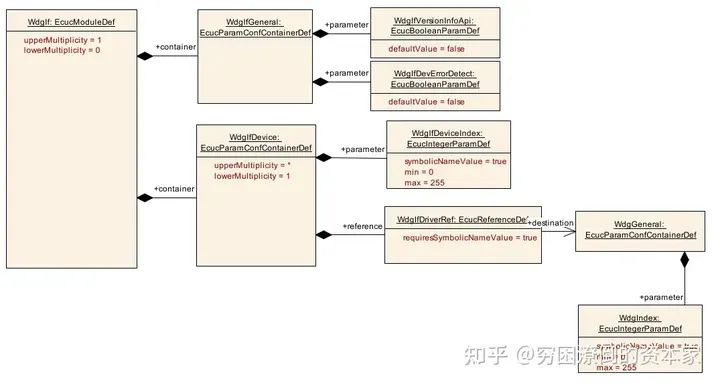
WatchDog Interface Parameters
10
WatchDog Manager
1. Basic Working Process
When Supervised Entities execute, whenever reaching a specific Checkpoint, the corresponding WdgM interface will be called to report the status. A Supervised Entity can have one or more Checkpoints, and the relational information within the Supervised Entity forms a Graph, also referred to as an Internal Graph. The association of Checkpoints between different Supervised Entities forms an External Graph. Each WdgM mode can have multiple External Graphs, and within a Graph, there can be multiple Initial Checkpoints or multiple Final Checkpoints. In this case, regardless of which Initial Checkpoint the execution flow starts from, it can end at any Final Checkpoint.
A Supervised Entity can set multiple Supervision mechanisms simultaneously. Based on the status returned by each mechanism, the current status of the Supervised Entity can be calculated, i.e., Local Status. Once the status of each Supervised Entity is obtained, the overall MCU status can be computed, i.e., Global Supervision Status. Each supervision function will return a status list, representing correct or incorrect. Finally, for each Supervised Entity, there will be three statuses: Alive Supervision status, Deadline Supervision status, and Logical Supervision status. The function WdgM_CheckpointReached() will update the status of Deadline Supervision and Logical Supervision, and executing WdgM_Mainfunction() will update the status of Alive Supervision.

Overall Working Process
2. Local Status Update
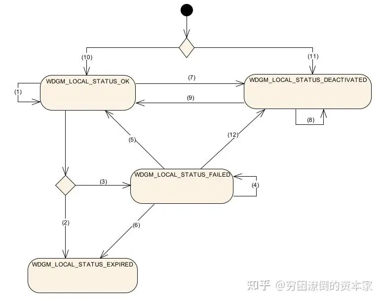
Local Supervision Status
-
Path 1: If all three monitoring states return correct, and the last recorded local status is OK, the local status will remain in OK state.
-
Path 2: If the last recorded local status is OK, the local status will be EXPIRED when any one of the conditions is met: at least one Alive Supervision returns incorrect, and the tolerance is set to 0; at least one Deadline Supervision or Logical Supervision returns incorrect status.
-
Path 3: If the last recorded local status is OK, while meeting the following two conditions, the local status will be FAILED: at least one Alive Supervision returns incorrect, and the tolerance is greater than 0; all Deadline Supervision or Logical Supervision return correct status.
-
Path 4: If the last recorded local status is FAILED while meeting the following two conditions, the local status remains FAILED: at least one Alive Supervision returns incorrect, and the failure count is less than the tolerance; all Deadline Supervision or Logical Supervision return correct status or at least one Alive Supervision returns incorrect, and the error count is greater than 1; all Deadline Supervision or Logical Supervision return correct status.
-
Path 5: If the last recorded local status is FAILED while meeting the following two conditions, the local status will be OK: all Alive Supervision return correct, and the error counter equals 1; all Deadline Supervision or Logical Supervision return correct status.
-
Path 6: If the last recorded local status is FAILED, while meeting any of the following conditions, the local status will be EXPIRED: at least one Alive Supervision returns incorrect, and the failure count equals the tolerance; at least one Deadline Supervision or Logical Supervision returns incorrect status.
-
Path 7: If activated and then disabled, set to DEACTIVATED status.
-
Path 8: If disabled and the Wdg function does not supervise any SE, it will remain in DEACTIVATED status.
-
Path 9: If activated after being disabled, switch to OK status.
-
Path 10: After WdgM initialization, the local status of the SE activated in initialization mode will be in OK status.
-
Path 11: If not in initialization mode, the local status of the SE will be in DEACTIVATED status.
-
Path 12: If the last status was FAILED, switching to DEACTIVATED status after being disabled.
3. Global Status Update
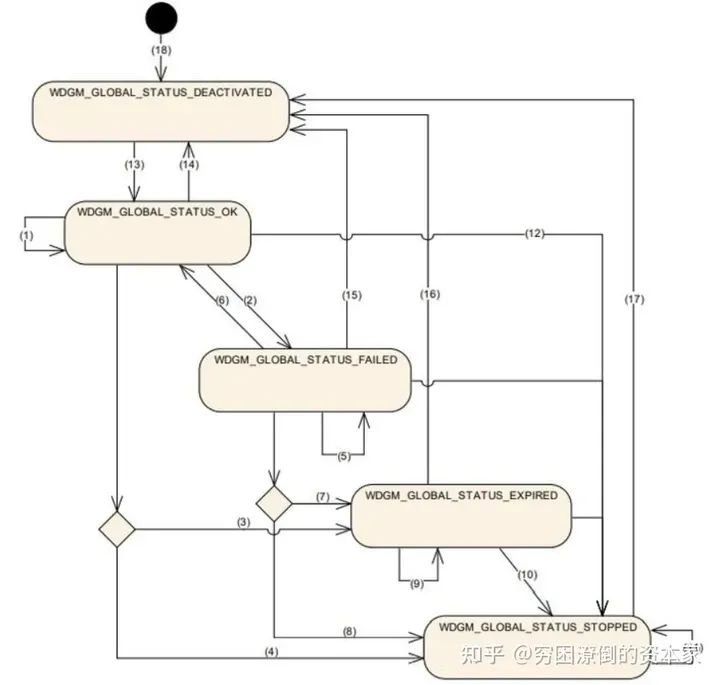
Global Status Update
-
Path 1: If the last recorded global status is OK, and the current SE’s local status is OK or DEACTIVATED, the global status remains OK.
-
If the last recorded global status is OK, and the current SE has at least one local status that is FAILED, and no SE status is EXPIRED, the global status is FAILED.
-
If the last recorded global status is OK, and the current SE has at least one local status that is EXPIRED, and it does not exceed the threshold, the global status is EXPIRED.
-
If the last recorded global status is OK, and the current SE has at least one local status that is EXPIRED, and it exceeds the threshold, the global status is STOPPED.
-
If the last recorded global status is FAILED, and the current SE has at least one local status that is FAILED, and no EXPIRED, the global status will remain FAILED.
-
If the last recorded global status is FAILED, and the current SE’s local status is OK or DEACTIVATED, the global status is OK.
-
If the last recorded global status is FAILED, and the current SE has at least one local status that is EXPIRED, and it does not exceed the threshold, the global status is EXPIRED.
-
If the last recorded global status is FAILED, and the current SE has at least one local status that is EXPIRED, and it exceeds the threshold, the global status is STOPPED.
-
If the last recorded global status is EXPIRED, and the current SE has at least one local status that is EXPIRED, and it does not exceed the threshold, the global status will remain EXPIRED.
-
If the last recorded global status is EXPIRED, and the current SE has at least one local status that is EXPIRED, and it exceeds the threshold, the global status is STOPPED.
-
If the last recorded global status is STOPPED, the global status will remain STOPPED.
-
If calling WdgIf_SetMode fails, the global status is STOPPED.
-
Path 13: After calling the WdgM initialization function, the global status is OK.
-
Path 14: If the last global status was OK, after successfully calling WdgM_DeInit, the global status is DEACTIVATED.
-
Path 15: If the last global status was FAILED, after successfully calling WdgM_DeInit, the global status is DEACTIVATED.
-
Path 16: If the last global status was EXPIRED, after successfully calling WdgM_DeInit, the global status is DEACTIVATED.
-
Path 17: If the last global status was STOPPED, after successfully calling WdgM_DeInit, the global status is DEACTIVATED.
-
Path 18: The global status of WdgM is initialized to DEACTIVATED.
11
WatchDog Service Working Principle
1. Alive Supervision
1. Parameter Configuration
The following diagram shows the monitoring method of Alive Supervision, where the monitored entity SE3 has only one Checkpoint3-1.
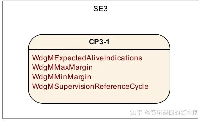
Alive Supervision Parameters
In the above diagram, we see the configuration of Alive Supervision, which requires setting the following four basic parameters:
-
WdgMExpectedAliveIndications: The number of times a monitored entity SE calls the WdgM_CheckpointReached function within a given time, i.e., the Expected value;
-
WdgMMaxMargin: The offset value for increasing the number of calls to the above function, i.e., actual value = Expected value + WdgMMaxMargin;
-
WdgMMinMargin: The offset value for decreasing the number of calls to the above function, i.e., actual value = Expected value – WdgMMinMargin;
-
WdgMSupervisionReferenceCycle: The number of times the WdgM_Mainfunction is called as a monitoring reference cycle.
2. Working Principle
-
Call WdgM_CheckpointReached once –> Send an Alive indication –> Alive Counter +1
-
Set WdgMSupervisionCycle, which should be an integer multiple of WdgMSupervisionReferenceCycle.
-
If WdgM_CheckpointReached calling count is within the range of Expected-MinMargin < WdgM_CheckpointReached calling count < Expected+MaxMargin, it will report a monitoring error status, which will affect the Local Status of that SE.
-
To avoid situations where the WdgM_CheckpointReached function call count is 0 or 1 within a time setting, which may occur even if the monitored entity is no longer executing, it is generally recommended to select the least common multiple of the WdgM main function cycle and the task cycle where the monitored entity SE resides as the monitoring reference cycle, ensuring that the number of WdgM_CheckpointReached() function calls within each monitoring reference cycle is a fixed value, while both upper and lower deviations MinMargin and MaxMargin are set to 0.
2. Deadline Supervision
Deadline Supervision is mainly used for non-periodic monitored entities SE, which are often triggered by events. The execution time of the monitored entity SE after triggering should not be too long or too short, and this execution duration needs to be limited by corresponding thresholds to monitor its operational status to meet design requirements.
1. Parameter Configuration
For each SE’s Deadline Supervision, two Checkpoints must be configured, as Deadline Supervision monitors the execution time between two Checkpoints, i.e., the dynamic behavior of the monitored entity SE.
The following diagram shows the monitoring method of SE4’s Deadline Supervision, which has a Start Checkpoint4-1 and an End Checkpoint4-2.
Basic parameters are as follows:
-
WdgMDeadlineMin: The minimum time taken between two Checkpoints during the Transition;
-
WdgMDeadlineMax: The maximum time taken between two Checkpoints during the Transition;
The following diagram shows the monitoring method of SE4’s Deadline Supervision, which has a Start Checkpoint4-1 and an End Checkpoint4-2.
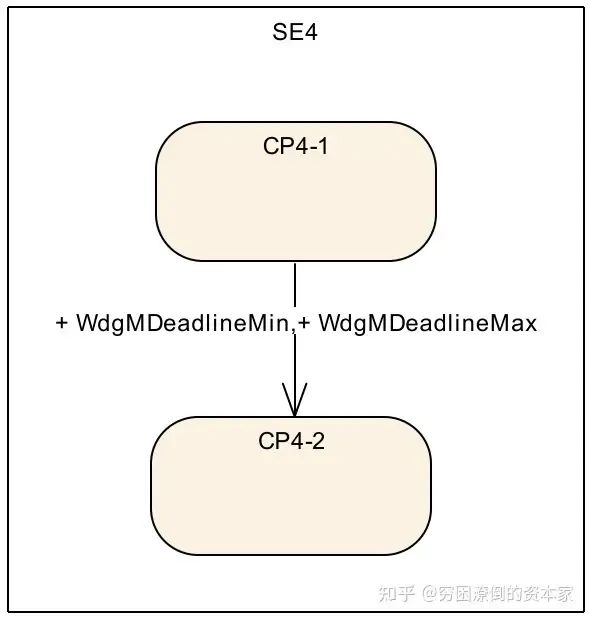
Deadline Supervision Monitoring 1
The following diagram shows a scenario where a certain SE entity has multiple Checkpoints simultaneously. In this scenario, there is not much correlation between them, only measuring the execution time between adjacent Checkpoints. It is important to note that different Checkpoints in this type of monitored SE should not allow nested behavior, such as CP Start1, CP Start2, CP End2, CP End1.
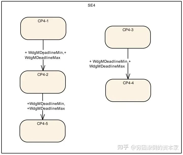
Deadline Supervision Monitoring 2
2. Working Principle
-
For this monitoring mode, two types of Start Checkpoints and End Checkpoints must be configured: Start Checkpoint –> set by parameter WdgMDeadlineStartRef; End Checkpoint –> set by parameter WdgMDeadlineEndRef.
-
Use the OS Counter to calculate the time interval between the two Checkpoints.
-
To determine the timestamp when WdgM_CheckpointReached is called and the time taken during the Transition between the two Checkpoints, the function WdgM_CheckpointReached needs to use OS functions to calculate the time difference between the two Checkpoints.
-
By comparing the OS tick time experienced between the two Checkpoints with the configured time parameters WdgMDeadlineMin and WdgMDeadlineMax, if it exceeds the limit, it will report a monitoring error for that monitored entity’s Deadline Supervision.
3. Logical Supervision
1. Configuration Process
For each Logic Supervision, the Transition between each Checkpoint forms a Graph, abstracting the execution timing flow of the code logic. The following diagram shows a normal execution program timing flow example in Autosar:

Program Flow Monitoring in Autosar Example
The above diagram depicts the possible paths of program execution, each path being set by Checkpoints, thus obtaining all possibilities. The Transition relationships of these Checkpoints need to be reflected in the configuration.
2. Working Principle
-
When the program runs to a Checkpoint, it calls the WdgM_CheckpointReached() function;
-
Within this function body, the last Checkpoint ID and the Transition ID between the two Checkpoints will be recorded. The Transition ID is calculated based on the adjacent two Checkpoints. If the Transition between adjacent Checkpoints is not the expected Transition, it will report an error in the Logic Supervision status of that monitored entity.
Source: Zhihu: The Impoverished Capitalist
Link: https://www.zhihu.com/question/315309637/answer/3348304856
Recommended Premium Activities


More Articles
Lawyer’s Statement on Suspected Imitation of AutoSec Conference Brand
An Article to Help You Understand the In-Vehicle Network Communication Security Architecture of Smart Cars
Cybersecurity: TARA Methods, Tools, and Cases
Key Analysis of Automotive Data Security Compliance
A Brief Analysis of Automotive Chip Information Security and Secure Boot
Exploration of Automotive In-Vehicle Communication Security Solutions in Domain-Centralized Architecture
Vehicle Network Security Architecture in System Security Architecture
Privacy Protection Issues in the Internet of Vehicles
Research on Cybersecurity Technologies for Intelligent Connected Vehicles
Analysis of the AUTOSAR Information Security Framework and Key Technologies
What Information Security Mechanisms Does AUTOSAR Have?
The Underlying Mechanisms of Information Security
Automotive Cybersecurity
Usage of AUTOSAR Hardware Security Module HSM
First Release! Lei Jun from Xiaomi Suggests on Automotive Data Security Issues during Two Sessions: Suggestions on Building a Complete Automotive Data Security Management System