This article will introduce the application of Schneider Electric’s M200 PLC communicating with a laser range sensor using MODBUS.
1
Case Description
This case introduces the Modbus-RTU serial communication between the PLC and the laser sensor through the laser sensor connected to the TM200CE24T serial port, includinghardware wiring, serial communication parameter configuration, and program writing, as shown in Figure 1, with the specific requirements as follows:
1
Configure communication parameters according to the laser sensor manual.
2
Read the distance from the laser sensor and store it in the local register %MW400.
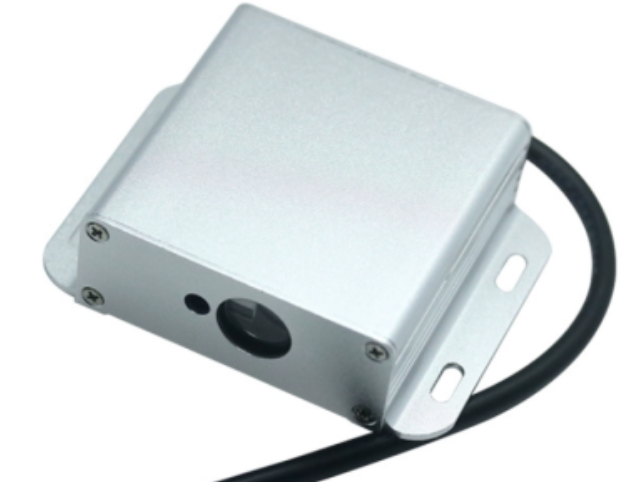
Figure 1 Laser Range Sensor
2
Preparation
1. High-speed laser range sensor
Its features are:
1
Supports MODBUS_RTU protocol
2
Has 0~10V voltage output and 4~20mA current output
3
Relay switch output with window detection function
4
Measurement range of 30 meters
5
Address can be set arbitrarily: 4~F5
6
Adjustable baud rate
7
Output 7/8 byte mode adjustable
Specific parameters can be found in Table 1⬇
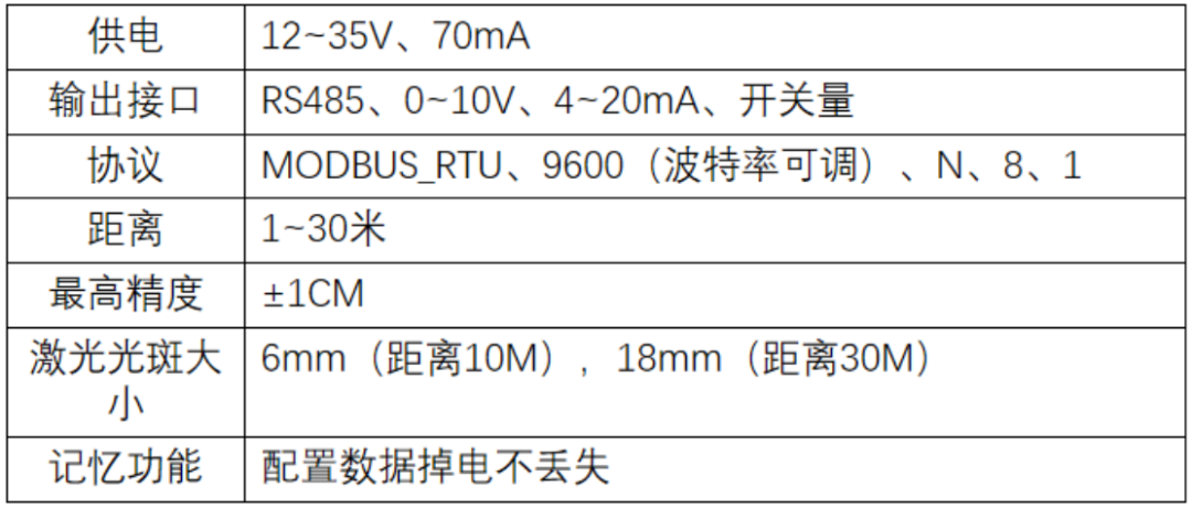
Table 1 Specific Parameters of Laser Range Sensor
2. High-speed laser range sensor wiring definition
When using the high-speed laser range sensor for MODBUS_RTU communication, the following is required:Power line (red and black wires),Communication line (green and blue wires), detailed color wire definitions are shown in Figure 2.
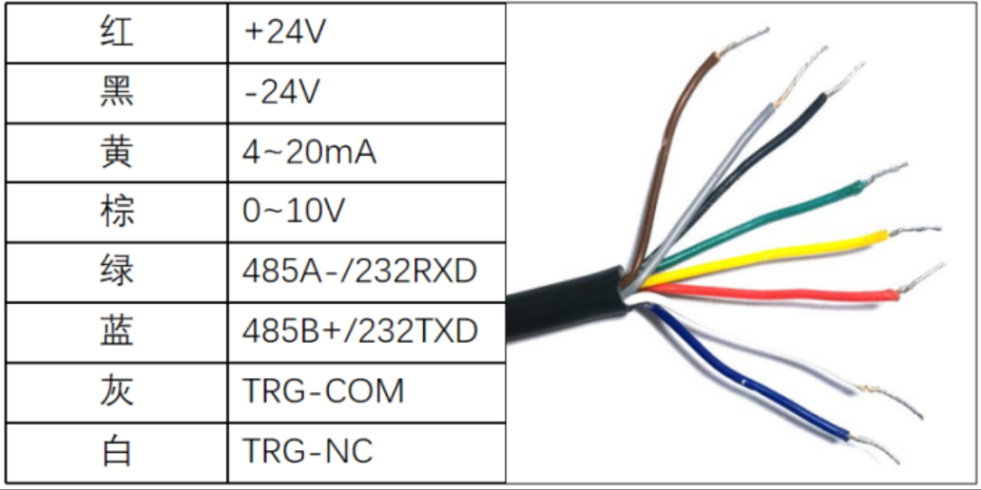
Figure 2 High-speed Laser Range Sensor Color Wire Definition
3. High-speed laser range sensor register definition
For MODBUS_RTU communication, the register definitions of the high-speed laser range sensor are as follows:
00Read-only register (caches distance, this register is the real-time distance value, reading once returns the current distance)
06Read-write register (device address, default value is 0X0016)
07Read-write register (device baud rate, default value is 0X0001, indicating 9600 baud rate)
08Read-write register (return data packet length, default value is 0X0007, indicating 7-byte return packet length)
09Read-write register (indicates laser switch, default value is 0X0001, indicating laser is on)
10Read-write register (analog distance upper limit 0X0A, default value is 0X0190, indicating 400CM)
11Read-write register (analog distance lower limit OX0B, default value is 0, indicating 0CM)
12Read-write register (analog output voltage range 0X0C, default value is 0X0000, indicating output voltage range 0-10V)
13Read-write register (analog output current range 0X0D, default value is 0X0001, indicating output current range 4-20mA)
14Read-write register (switch output long-distance threshold 0X0E, default value is 0X0190, indicating 400CM)
15Read-write register (switch output long-distance threshold hysteresis value 0X0F, default value is 0X0005, indicating hysteresis distance value is 5CM)
16Read-write register (switch output short-distance threshold point relay switch type, greater than threshold relay pulls in or disconnects 0X10, default value is 0X0002, indicating relay disconnects when greater than long-distance threshold)
17Read-write register (switch output short-distance threshold 0X11, default value is 0X0032, indicating 50CM)
18Read-write register (switch output short-distance threshold hysteresis value 0X12, default value is 0X0005, indicating hysteresis distance value is 5CM)
19Read-write register (switch output short-distance threshold point relay switch type, reaching threshold relay pulls in or disconnects 0X13, default value is 0X0001, indicating relay pulls in when greater than short-distance threshold)
20Write-only register (restore factory settings 0X14, default value is 0X0000, writing 1 indicates restore factory settings, automatically zeroing)
21Read-write register (set measurement frequency 0X15, default value is 0X0006, indicating 100HZ)
Table 2 is an example of sensor messages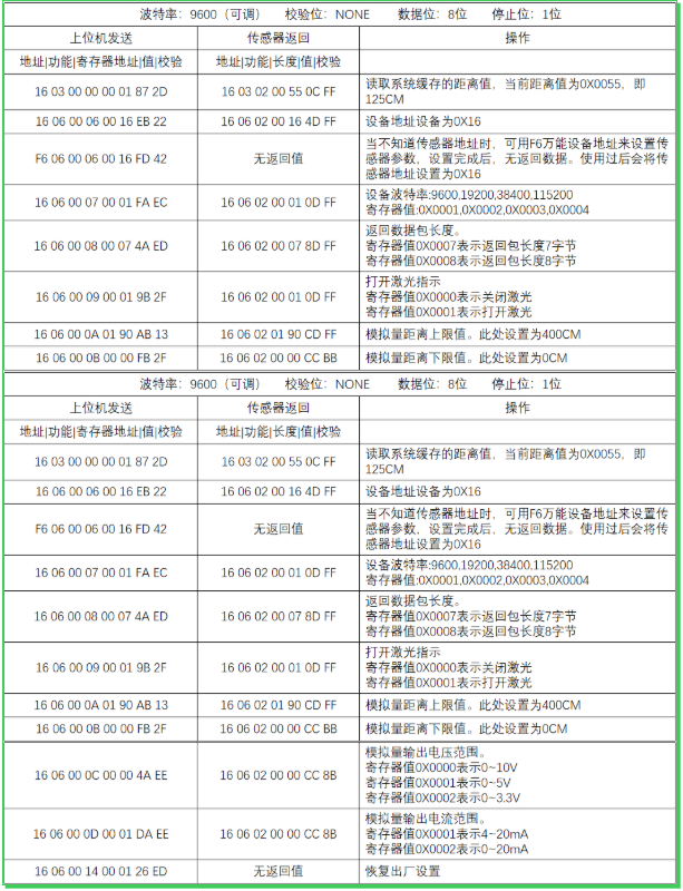
Table 2 Example of Laser Range Sensor Messages
3
Case Implementation
The implementation steps of this case are mainly divided into three parts: the communication connection between the M200 PLC and the laser range sensor, hardware configuration, and software programming.
1. Communication connection between M200 PLC and laser range sensor
Since the communication interface of the laser range sensor is of type 485, which is the same as that of the M200, there is no need for a converter for the communication ports; they can be directly connected. The schematic wiring diagram is shown in Figure 3. The red and black wires of the laser range sensor connect to 24V, the green wire connects to D1 of TB Serial 2 in the M200 PLC, and the blue wire connects to D0 of TB Serial 2 in the M200 PLC.
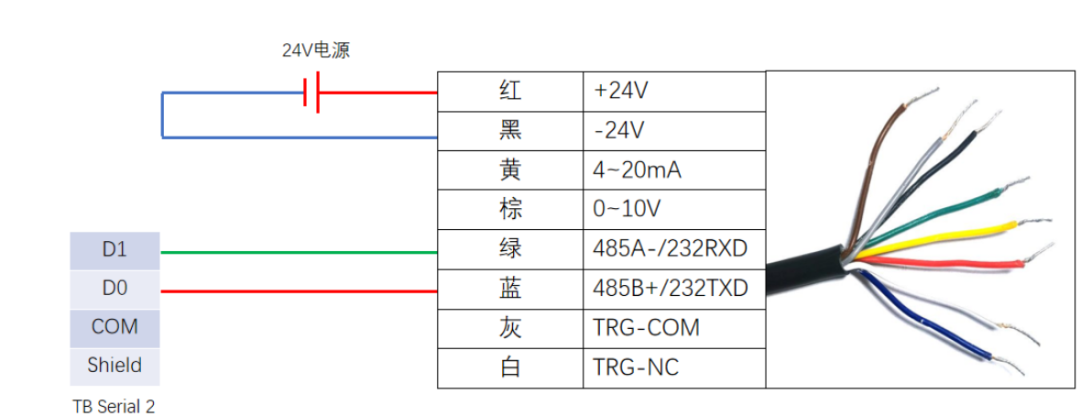
Figure 3 Schematic Wiring Diagram
2. Hardware Configuration
1
Open the “EcoStruxure Machine Expert-Basic” software, create a new project, and add“TM200CE40T” and “TM3RDM32R”, save the project name as “Laser Range Sensor Serial Communication Case.smbp”.
2
In the configuration interface, click on “SL1 (Serial Line)” to enter the serial port 1 configuration interface, select the protocol “Modbus Serial IOScanner”, select baud rate “9600”, select parity “None”, select stop bits “1”, and click “Apply” to confirm. As shown in Figure 4
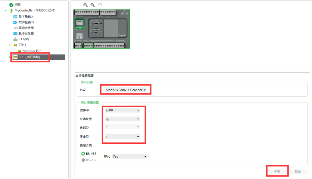
Figure 4 Modbus Communication Parameter Configuration
3
Click on “Modbus Serial IOScanner”, enter the “IOScanner” configuration interface, in the protocol settings section, select the transmission mode “RTU”, with other settings as default. In the device settings section, click “Other”, select “Generic device”, click “Add”, and the table below will display the newly added device. As shown in Figure 5. Click on “Initialize Request” below the icon, enter the initialize request assistant interface, in the channel assistant interface, right-click to delete the initialize request, and click “OK”. As shown in Figure 6.
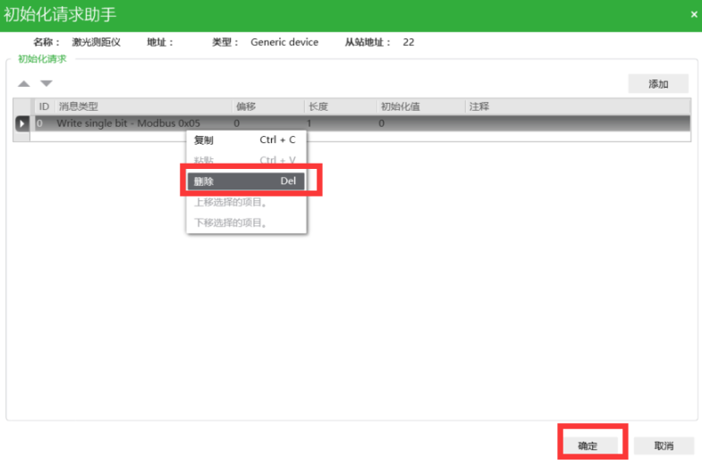
Figure 5 Add Modbus Slave
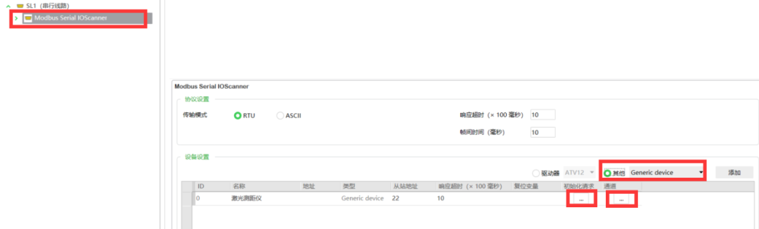
Figure 6 Delete Initialize Channel
4
In the “Modbus Serial IOScanner” configuration interface, click on “Channel” below the tab, enter the channel assistant interface, then click on “Configure” below the icon, and enter the channel 0 configuration interface. As shown in Figure 7.
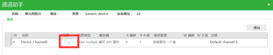
Figure 7 Channel Assistant Interface
5
In the channel 0 configuration interface, select message type “Read multiple words-Modbus 0x03”, which represents reading the values of multiple holding register addresses, set the read object offset to “0”, and set the length to “2”, indicating that the master reads the values of slave registers 40001 and 40002, and click “OK”. After confirmation, the page shown in Figure 7 will be displayed, continue to click “OK”, and after confirmation, the page shown in Figure 5 will be displayed, click “Apply”, completing the Modbus hardware configuration.
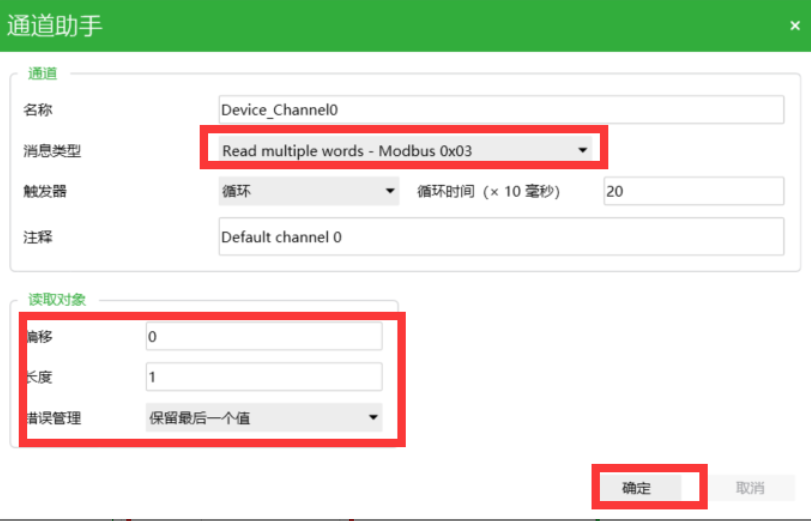
Figure 8 Channel 0 Address Configuration
3. Software Programming
1
Enter the programming interface, refer to Figure 9, and write the program.

Figure 9 Laser Range Sensor Program
2
Compile and download the program, monitor the distance value online, and observe that the current distance is 18cm. As shown in Figure 10.

Figure 10 Online Monitoring of Distance Value
↓Scan to join the Industrial Control Community↓↓See more technical cases ↓