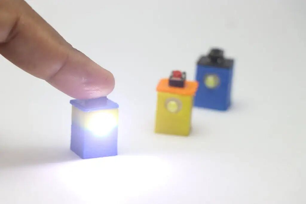
Attention all DIY enthusiasts! Today, I want to showcase my freshly made “palm-sized gadget”—a mini flashlight that is fully 3D printed and comes with wireless charging!✨
Clear goal: To create a super small, super bright, and super convenient portable light companion! Going out for a stroll, looking for keys, or checking under the bed? No pressure at all to fit it in your pocket!
How small is it? You might not believe it! The entire flashlight has a diameter of less than 2 centimeters! Put a coin in front of it? Wow, the coin can completely cover it! Is this size unbelievable enough?🤏
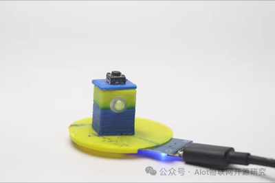
Charging? Even cooler! I equipped it with a dedicated “energy station”—a compact wireless charging pad. Finished using it? Just place it on the pad, and it starts charging automatically! Say goodbye to the hassle of finding cables and sockets, how tech-savvy is that?
Don’t be fooled by its mini size, the battery life is quite impressive (for its size, of course). I made the entire lamp body fully sealed, as for the waterproof performance… cough, cough, it’s still a “theoretical” claim; I haven’t actually tested it in water yet. When I muster the courage to test it, I’ll report back to everyone!💧
What’s the best part? The entire flashlight frame components are all 3D printed! What does this mean? Precision! Convenience! Say goodbye to the troubles of marking lines and drilling holes! It’s simply a blessing for efficiency enthusiasts!🖨️
Helpful tip: You can even add a small hole to the shell to turn it into a keychain accessory! However… I personally didn’t add one (why?). Because this treasure is just too cute and exquisite, I’m afraid if I hang it on my keys… the attention it attracts might lead to it being stolen! (Haha, just kidding, don’t take it seriously!😜)
So, what do you think? Wireless charging + extreme mini size + 3D printing + sealed design… Is this operation cool enough? To accommodate wireless charging, I put a lot of effort into waterproof sealing (even though I haven’t tested it in water yet…)!
Feeling excited to get started? Don’t rush! Let’s dive in and build this little cutie together!
⚠️ Friendly reminder: This project requires a bit of patience! Why? Because we are dealing with tiny electronic components! It’s a delicate task, so no rushing!
Those who dare to take on this “micro-sculpture” level project are true DIY enthusiasts! If you’re eager to try, I wholeheartedly support you! I can’t wait to see your “buyer’s show” and “I made it” photos in the comments! Looking forward to your submissions!🔥
Materials List:
The materials for making this flashlight include several electronic components that I salvaged from old devices! If you also have a “disassemble” spirit, I strongly recommend checking your electronic waste pile! If you really don’t have any? Don’t worry, the all-powerful online shopping platforms can solve it in no time! 🛒
Here’s the core electronic components list, get ready!👇
-
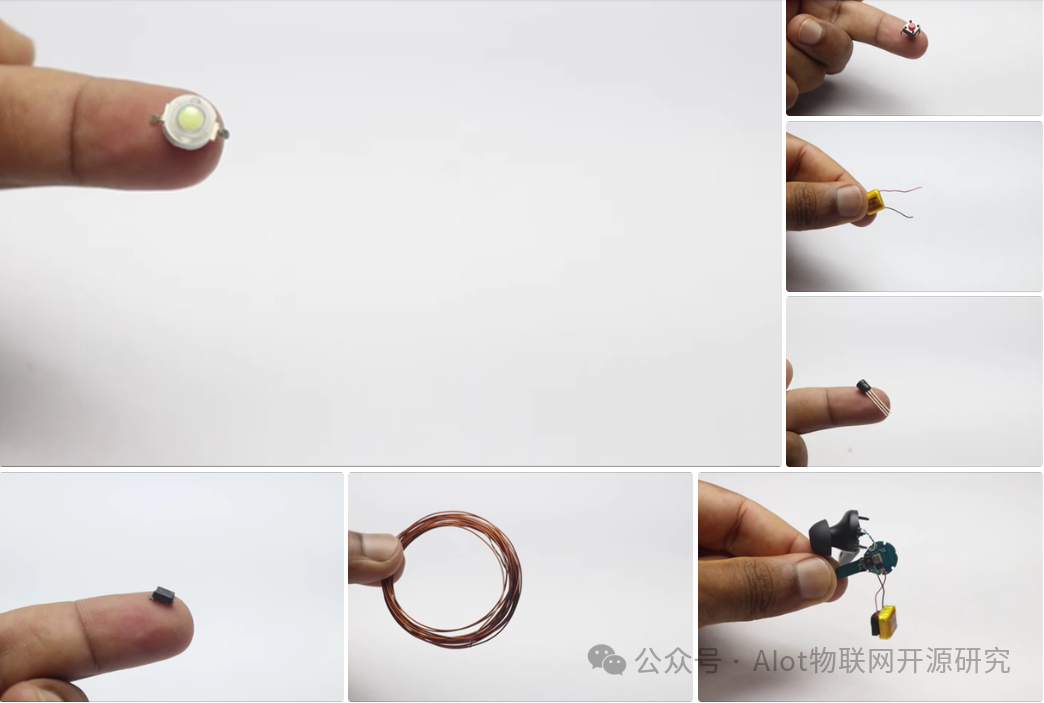
Light bulb: 1 watt (1W) LED ➡️ The brightness champion, relying on this “little sun”!
-
Switch: Push button switch ➡️ A tiny one, pressing it is super satisfying~
-
Battery: Small lithium polymer battery ➡️ (Mine: salvaged from an old headset!) Old headsets/small devices often have surprises!
-
2N2222A Transistor ➡️ The current control expert, don’t buy the wrong model!
-
Diode ➡️ (Mine: recycled!) Prevents current from flowing backward.
-
Insulated copper wire ➡️ The “veins” for internal connections, thinner ones save space.
-
3D printer ➡️ Without it, how would we make the frame? The soul device!
-
Slicing software ➡️ Cura/PrusaSlicer… Let your model “understand” the printer’s language.
-
Quick-drying glue/super glue ➡️ Sealing and fixing rely on it, the key to waterproofing!
-
PLA filament ➡️ The “dough” for printing the shell, choose any color you like!
-
Soldering iron + solder ➡️ Essential for “connecting” electronic components! Precision work, stability is key!
-
TP4056 charging module ➡️ (The one with a lithium battery protection board!) Gives it the “superpower” of wireless charging!⚡
-
USB data cable ➡️ Powers the charging module, a regular Android cable will do.
Design and 3D Printing:
Before making this mini flashlight, the first step is to complete the structural design. My core goal is: to ensure extreme miniaturization while ensuring the structure is strong enough to withstand minor impacts during daily use.
Key design constraints: The shell must securely accommodate all internal electronic components. To achieve this, I went through multiple design iterations, considering size, strength, and internal layout before finalizing the current design scheme.
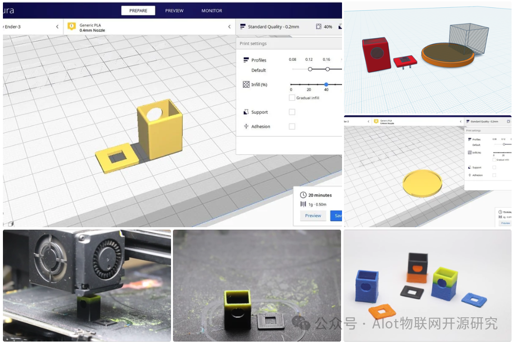
Design tools: I used the Tinkercad application for modeling. This tool allows for easy customized design based on the dimensions of standard electronic components.
Printing preparation:
-
After completing the model design, export it as an STL file.
-
Use Cura slicing software for slicing. Specific printing parameter settings can refer to the illustrations later in the text.
-
Important note: There’s no need to use a raft or support structures for printing this model, simplifying the printing process.
Design features:
-
Simplified and efficient structure: Although the shape is simple, the internal space is optimized to fully accommodate all micro components.
-
Modular design: The shell consists of 3 independent parts:
-
Base frame
-
Top lid
-
Charging board holder
-
Printing strategy: The base frame and top lid are printed as a set, while the charging board holder is printed separately.
Materials and appearance:
-
Using PLA filament for printing.
-
I tried various color combinations (like black, blue, orange, etc.), and the final effect exceeded my expectations. You can choose a monochrome or contrasting color design based on personal preference.
https://content.instructables.com/F8R/0GCD/MBJDZU8V/F8R0GCDMBJDZU8V.stl
https://content.instructables.com/FBQ/9XT1/MBJDZU98/FBQ9XT1MBJDZU98.stl
Circuit Making and Wireless Charging Principles
Before officially assembling the circuit, I first recycled old components: including the battery and diode.
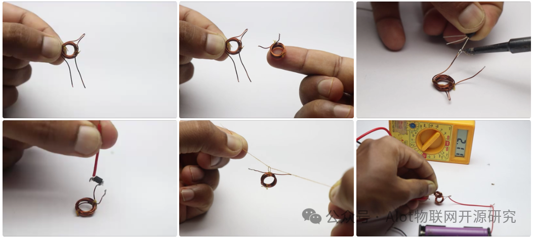
Step 1: Making the Electromagnetic Induction Coil
-
Winding the coil: Use a pen barrel as a mold, tightly wrap insulated copper wire around it to form a coil.
-
Securing the coil: Use cotton thread to tie the wound coil, preventing it from loosening or deforming.
Step 2: Coil Preprocessing and Soldering
-
According to the circuit diagram, carefully scrape off the insulation paint layer on the coil surface at the soldering points, exposing the metal conductor.
-
Solder the wires at this exposed area.
Step 3: Recycling Lithium Battery
-
I salvaged a lithium polymer (LiPo) battery from a damaged old Bluetooth speaker. These batteries still have value and gain a “second life” in this project.
-
How to operate: Open the headset or device casing, desolder the battery leads from the original circuit board for future use.
Step 4: Wireless Charging Circuit Principle
-
We will build a wireless power transmission circuit based on electromagnetic induction principles, which operates on the same basic principle as common wireless charging devices but will use alternative components.
-
Core components:
-
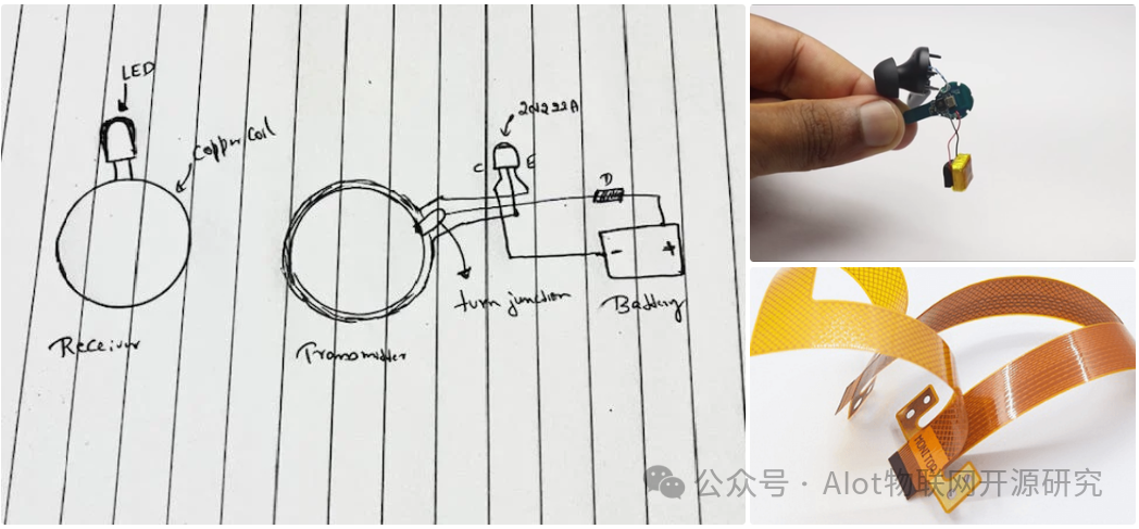
Transmitter: Composed of a coil wound with insulated copper wire, connected to the power supply circuit.
-
Receiver: Also composed of a coil made of insulated copper wire, its end directly connected to the LED (our light source).
-
Circuit diagram explanation: The receiver circuit is as shown in the attached diagram, but includes additional components (diodes, transistors, etc.) to meet functional requirements.
Step 5: Overall Circuit Design Points
-
Considering the portability of the flashlight, it must include battery power.
-
We are constructing a basic battery-powered LED lighting circuit, integrating switch control and diode protection.
-
Key component functions:
-
Diode: Suppresses reverse current, protecting the circuit.
-
Transistor (2N2222A): Amplifies and stabilizes the weak and unstable electrical energy sensed by the receiver, allowing it to effectively charge the battery (even under low power conditions).
Step 6: Circuit Testing
-
Assemble the circuit according to the circuit diagram.
-
Preliminary test to check if the circuit functions normally.
-
Wireless charging function test:
-
Connect a multimeter to both ends of the receiver coil.
-
Use the TP4056 charging module to power the transmitter circuit (input 5V).
-
Observation results: The transmitter output is 5V, but due to transmission loss, the induced voltage at the receiver end is usually only about 3V.
-
This induced voltage fluctuates significantly, making it unsuitable for direct battery charging.
-
Solution: Use the transistor to stabilize and amplify the electrical energy at the receiver end, outputting stable usable current for battery charging.
Final Assembly and Function Testing
After completing the circuit testing and confirming the multimeter readings are normal, we can proceed with the final assembly:
-
Connect core components and test:
-
Connect the battery, diode, and switch to the receiver circuit.
-
Test if the flashlight can light up normally.
(Recommended) Battery endurance test:
-
It’s advisable to conduct a battery endurance test: Keep the flashlight lit until the battery runs out, recording the time. This helps understand the actual usage duration.
Importance of wire selection:
-
The specifications (thickness and flexibility) of the wires chosen for soldering are crucial. Soft, thin wires help the circuit flexibly route within the compact shell.
Switch handling and installation:
-
The toggle switch used has 4 pins, which are internally connected in pairs. The effective equivalent is 2 functional pins.
-
How to operate: Identify the pin groups that are connected in parallel, and cut off the excess pins in each group (keeping only one pin from each group).
-
Secure the switch: Use gel-type strong glue to firmly attach the switch to the designated position inside the 3D printed top lid.
-
Once the glue is fully cured, install the switch button (cap).
Switch soldering and testing:
-
Solder the switch leads from the bottom of the base frame.
-
Test the switch functionality again (it should reliably control the LED on and off).
Core assembly: Place components into the shell
-
Carefully organize the internal wires, ensuring the top lid can be installed smoothly without any obstruction.
-
Insert the battery.
-
Insert the LED, ensuring its position is adjusted so that the LED chip aligns precisely with the center hole at the front of the shell.
-
Apply a layer of gel-type strong glue around the gaps of the LED for fixing and initial sealing.
-
Apply a layer of gel-type strong glue to the bottom of the 3D printed base frame.
-
Carefully place the wound copper coil (receiver).
-
Step 1: Secure the receiver coil
-
Step 2: Place the battery and LED
-
Step 3: Organize wiring
-
Key tip: After each assembly step, be sure to test if the LED still works! Because once the top lid is closed, it will be very difficult to open it again for inspection.
Transmitter assembly (wireless charging base):
-
Follow similar steps and logic as above to complete the placement and securing of the transmitter circuit within its shell.
Final testing preparation:
-
At this point, the flashlight body (receiver) and the wireless charging base (transmitter) are both assembled and ready for final functionality and charging tests.