* This article is original by: OpenATS, and is part of the FreeBuf original reward program. Reproduction without permission is prohibited.

1. Introduction
The advent of SDR has allowed us, the less fortunate, to use high-end technology. SDR can do many things that traditional radios cannot, changing our perception of radio communication.
Those who play with radio probably know that when communicating with satellites, many satellites are not stationary, which necessitates an automatic tracking antenna. There are commercial tracking antennas available on the market, such as the Yaesu series, and of course, there are even more advanced options.
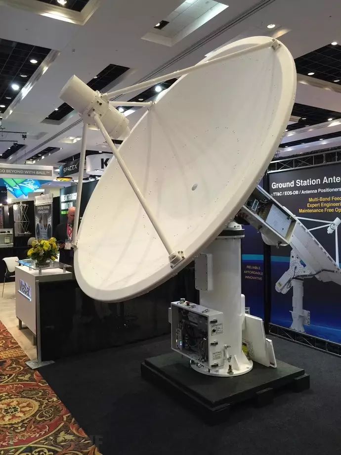
However, the price of commercial products is quite high, making them unattainable for us.
Foreign enthusiasts can use automatic tracking antennas to track satellites, not just limited to simple radio communication projects, but also to receive high-definition HRPT weather satellite images, while most domestic players do not have an automatic antenna, and even if they do, they are limited to simple radio communication.
After searching on Google, I found that there are open-source projects abroad, such as Bob’s Raspberry Pi-based CNCTRK, etc., as well as domestic tracking antennas made using camera gimbals with low precision.
Camera gimbals are not very precise but are low cost. If you only want to use them for simple radio communication projects, you can certainly follow that method.
But now I want a more precise, better-controlled antenna that is more suitable for future radio research. The foreign CNCTRK is also good, based on the Raspberry Pi’s LinuxCNC open-source system, which is a very good open-source project. If you need to know more, you can look up the information yourself.
However, I feel that the interface is not intuitive enough, not flexible enough, and I’m not very satisfied. So I decided to make it from scratch myself.
After researching various materials, I finally decided to use the open-source hardware platform Arduino to complete this project, and then more difficulties awaited me. I had never worked with Arduino before, and I started learning Arduino programming. Fortunately, it is based on C language, which is relatively easy to get started with.
Next, what motor should I use for the mechanical system? Servo? Stepper? What is a servo, and what is a stepper? I had never encountered these things before. I started learning from scratch, accumulating knowledge bit by bit, and this process was very difficult.
I began to understand why so many enthusiasts around the world, despite the large number of them, so few people can create such a simple tracking system. On the surface, it seems very simple, but it involves too much knowledge, including computer programming, electrical knowledge, microcontroller programming, mechanical design, geographical knowledge, radio knowledge, and so on.
The image below is a diagram of the azimuth angle, 360 degrees in a week.
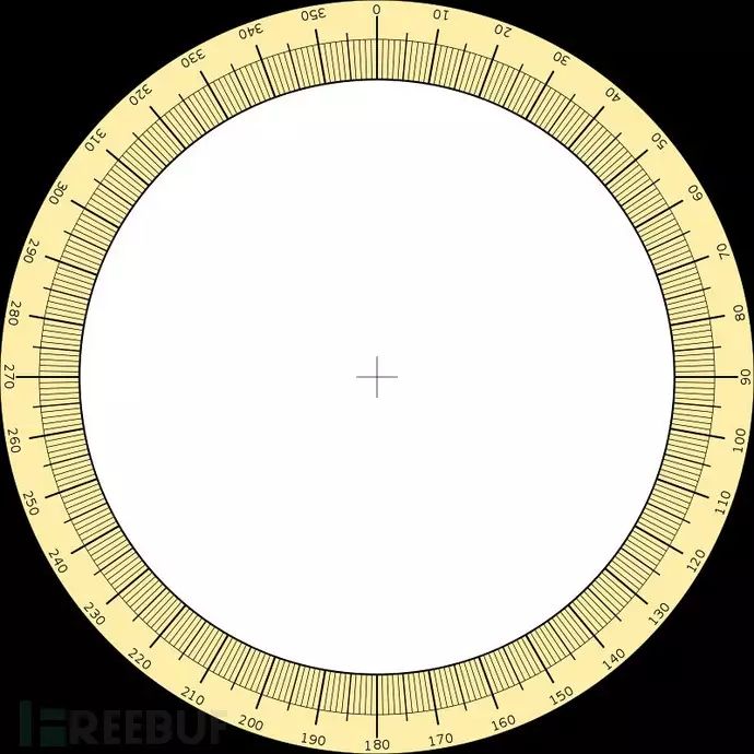
The more difficult it is, the more we must solve it.
Initially, my design was to use a cheap high-power DC motor combined with a precision potentiometer as an angle sensor, equivalent to DIYing a servo motor.
Why choose this? Because I have a discarded marine satellite communication antenna from Japan’s JRC company, which comes with a SANYO DC motor and high-precision potentiometer to form a closed-loop control, which can be equivalent to a servo motor. Since they can achieve it, I can too.
So I searched everywhere for how to use a potentiometer and a DC motor to do closed-loop control, and found many code examples. Thus began the long process of program design and programming. Finally, I finished writing it, and then built the hardware for testing, and at that moment I was dumbfounded.
Due to the large inertia of the antenna, my system could not brake at all, it was simply unusable, completely useless. DIY servos require hardware support, not just relying on Arduino as the controller. Moreover, the DIY servo circuit boards available domestically are also very expensive. Thus, I had to abandon this plan.
Later, I turned to using high-precision stepper motors. I was very satisfied with the cost and positioning accuracy of stepper motors, but more difficulties followed. Stepper motors are open-loop and have no feedback. How to reset the antenna? How to prevent losing steps? So I began to write the program, which included a step counting function for the stepper motor, allowing it to record all the steps taken and then reset.
Loss of steps can only be prevented through calibration and other methods. I also wanted to use servo motors for better maneuverability and angle control, but servos are too expensive. After completing the entire system, the cost was exorbitant and could not be popularized.
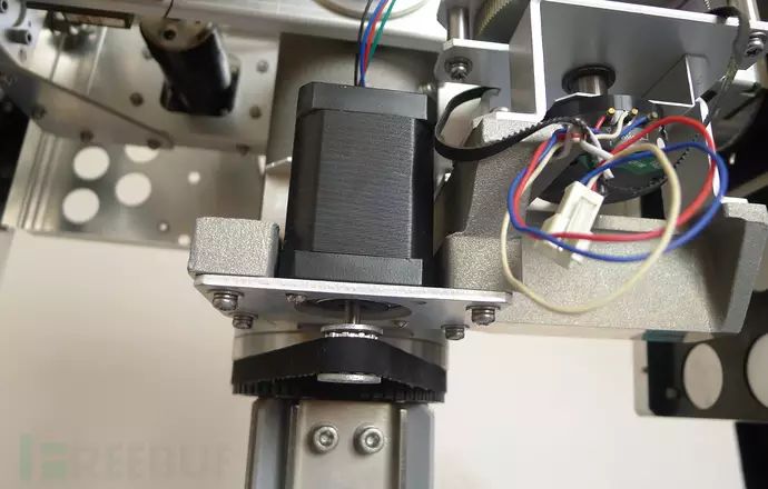
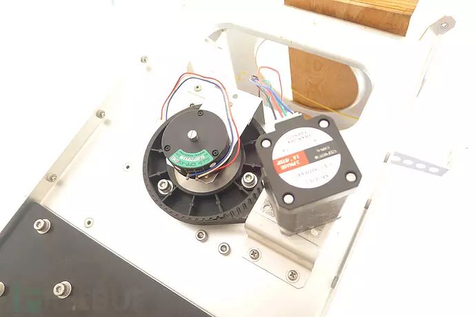
(The motors in the image below are non-finished products; the motor in the image had insufficient power after installation, and I replaced it with a 0.9N.m extended 42 stepper motor)
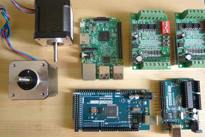
Later, I studied how to control industrial stepper motors using Arduino. Most of the articles in the country are about using Arduino to play with small motors. Very few people control industrial stepper motors. Even if there are, the code is very simple, and being able to control rotation is already good enough.
There is very little information on how to connect Arduino with industrial stepper drivers. The built-in stepper library can’t even control two stepper motors at the same time, which is a tragic process for a beginner. I started to scour Arduino forums for information and code.
It was a very difficult process, with no one around to help me. I could only search for information on domestic and foreign forums, using Baidu and Google. After a lot of effort, I finally wrote it, and the code could achieve simple functionality, but unfortunately, I discovered a better open-source stepper motor control library, AccelStepper, which made me feel like I had missed out.
Because this library is excellent, it has acceleration and deceleration and includes a step counting function, meaning that using this library, you don’t have to worry about those issues; you just tell the program how many degrees you want to rotate!
Once again, I had to make major revisions to the code. To say it was a major revision would be better to say I deleted everything and rewrote it…
First, I experimented with how to control the stepper motor and how to apply acceleration. Finally, I began designing the entire system. Using existing tracking software to create an upper computer (tracking platform) could greatly reduce my workload.
Moreover, the current tracking software is very good. After determining to use existing computer tracking software, I started looking for suitable software to act as the upper computer controller. There are many free satellite tracking software options, such as Orbitron, WXtrack, Xtracker, etc., all of which are quite good.
The domestic circle is limited to Orbitron. Although Orbitron performs well, it has not been maintained or updated for a long time, and the tracking protocols it supports are very few. WXtrack is considered by many to be the best satellite tracking software, and many foreign players agree.
I previously used WXtrack to track satellites. The author, David Taylor, despite being quite old, has continued to update and support the software. I am truly grateful for the contributions made by this veteran in the field of radio.
Below is the tracking interface of WXtrack
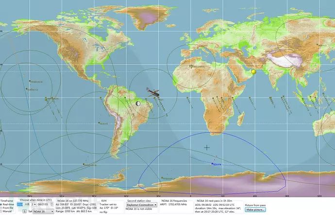
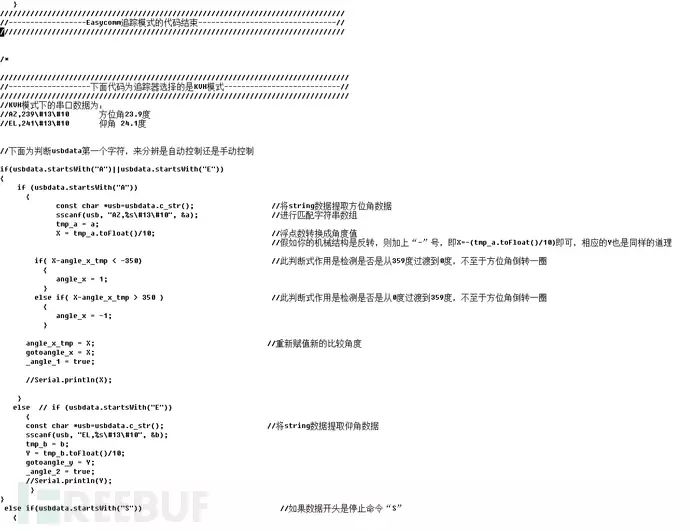
After confirming WXtrack as the tracking software, I began to delve into WXtrack. To use the tracking protocols supported by WXtrack to create my system, it would be even simpler. I studied all the control protocols provided by WXtrack and selected two: EasyComm and KVH.
The angle data sent by EasyComm’s serial port is intuitive, but if the software is not registered, the data sent can only be integers and cannot be precise to decimal points.
I contacted the author David Taylor via Twitter and discussed a lot. The author said that the latest upcoming beta version has already added this feature for free.
Unfortunately, such a good software is not open-source, and the code is not public. The KVH protocol data is sent through serial data capture, and it has a preserved decimal point after the angle value. Although it is an integer, moving the decimal point one place to the left gives a precision of 0.1 degrees, which is excellent.
The less perfect aspect is that it sends data separately. One data is AZ (azimuth angle), and another is EL (elevation angle), sent separately in a loop.
The consequence of this is that if I don’t implement manual control in the Arduino programming, the antenna will move to the azimuth angle first, then to the elevation angle, then back to the azimuth angle, and so on…
In other words, it looks very awkward and lacks any fluidity! Careful observers might think that this rotation method would greatly reduce accuracy! It would be impossible to align with the satellite!
Then I turned to EasyComm, and with a mischievous thought, I wondered if there was a cracked version of WXtrack. After searching on Google, I indeed found a registration tool for WXtrack version 3.8.28, which could completely crack it. I downloaded it to experiment and found that the cracked version could indeed output higher precision, and I retained two decimal points.
Of course, this behavior is indeed of low quality, but for us poor Chinese, I can only apologize to the selfless David Taylor. I am truly sorry.
If you can afford it, please purchase a legitimate serial number to support the author’s contributions. If you feel that this is not right, please comment out the EasyComm part of the code and use the KVH mode, which does not require registration and can meet the needs of most people.
To create a better antenna, I thought of many things. I added a manual control function, allowing us to control our antenna more flexibly and make it even better.
Having said so much about my thoughts and processes, I sincerely thank those who have read this far. The above is a brief account of my process in creating this system, and I won’t describe more details.
Since I also have a job, as an ordinary assembly line worker, this process took several months of effort. Regardless of how difficult the process was, fortunately, the system was completed.
This system is completely free and open-source, and it has a rather powerful name: OpenATS (Open Antenna Tracking System), close to OpenBTS…
This system can also develop into the field of drone tracking, radio radar, etc., as long as the output data format is defined as azimuth and elevation angles. It is easy to expand. Anyone can use it for free.
Originally, the antenna was already completed, but I had not released it due to a bit of selfishness.
After completing this antenna, I now have the capability to receive NOAA and China’s Fengyun meteorological satellites’ HRPT high-definition cloud images, using HackRF through GNU Radio to output .RAW16 radio data files, and then using Taylor’s HRPT Reader software to output high-definition satellite cloud images, surpassing those who have copied APT satellite cloud images for many years.
I wanted to release this antenna after receiving the first high-definition HRPT format cloud image of domestic amateur radio. However, my current living environment does not allow me to set up an antenna, and the electromagnetic environment is also terrible.
Thinking about it, I can’t be selfish anymore; let’s allow everyone to build their automatic antennas as soon as possible! Below are high-definition cloud images received by famous foreign players, using HackRF, GNU Radio, and HRPT Reader to decode. I hope more people will strengthen our amateur radio community in China.
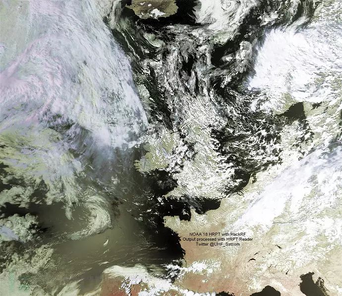
For more high-definition cloud images, please search on Google. I will also have some on my cloud disk.
I wish everyone can build their tracking antenna!
2. Production/Usage Process
Required Hardware:
A computer to run the WXtrack satellite tracking software.
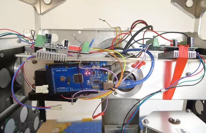
Arduino, either clone or original, the original can be purchased as Genuino, with versions like Nano and Mega. I recommend Mega for better processing power and memory, and easier expansion later. The domestic original version costs around 140 RMB. Nano costs about 80 RMB, and clones range from 30-50 RMB. Clones are also fine; my experimental platform runs on a clone.
Two stepper motors, preferably 57 stepper motors, with a larger torque choice, preferably above 2.0Nm. You can also increase torque through a gearbox.
Two stepper motor drivers, each controlling one stepper motor. A set of drivers costs around 200-300 RMB, and you can also look for second-hand ones.
A 24V switching power supply, industrial-grade is fine. There are many on Taobao, and the specific power depends on the total power of your two stepper motors. If you choose high-power 57 stepper motors, you need to select at least a 10A power supply.
Another inconspicuous but important part is a rotating XY-axis bracket. This is hard to purchase, and you may need to make it yourself; estimating the cost is difficult.
If you don’t count the bracket, you can complete the required functionality for just a few hundred RMB. Including the bracket, it should be less than 2000 RMB, depending on whether you use a gearbox and other components; many of these components are available around us.
Setup Process:
All programs and codes have been shared on my Baidu cloud disk. Address: http://pan.baidu.com/s/1jHYw80u
1. Install the Arduino driver program arduino-1.6.8-windows.exe, download and extract the AccelStepper library, and copy the entire AccelStepper folder into the libraries folder of the Arduino program after installation.
Finally, copy the tracking antenna code into the IDE and upload it to the Arduino development board.
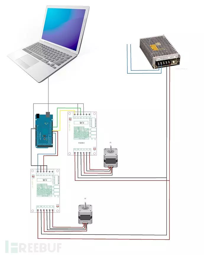
2. Set up the hardware. The specific hardware wiring is simple; just use the Arduino’s PWM interface to send pulses. The control interface for the azimuth angle is 3, the direction control is 5, the elevation angle control interface is 6, and the direction control is 9.
You can use common anode or common cathode connection methods (of course, you can modify the interface in the code to correspond with the external circuit).
Connect the AZ azimuth angle CLK+ (some drivers may also call it PUL+) to Arduino digital interface 3, CW+ (some may also call it DIR+) to digital port 5, EL elevation angle CLK+ to 6, and CW+ to 9.
Connect the CLK- and CW- of the AZ azimuth driver together and connect them to one of the Arduino GND interfaces. Connect the CLK- and CW- of the EL elevation driver together and connect them to another Arduino GND interface. The remaining EN+ (some may also call it ENA+) and EN- are not connected.
3. Connect the stepper motors to the drivers. For common 2-phase four-wire motors, connect A+, A-, B+, B- according to the markings on the driver. Connect the driver’s power supply to the output of the switching power supply, which supplies 24V power to both drivers.
Be careful with the positive and negative terminals.
The circuit diagram is as follows:
Usage Instructions:
(1) Automatic Tracking
For automatic tracking, go to my cloud disk to download WXtrack version 3.8.28 with a registration tool and run the cracked software (you must register or crack the software; you can also use the latest beta version released by Taylor). Update the ephemeris; if the ephemeris update prompts that it cannot connect to the internet or fails to update, manually download the ephemeris file and place it in the program’s folder.
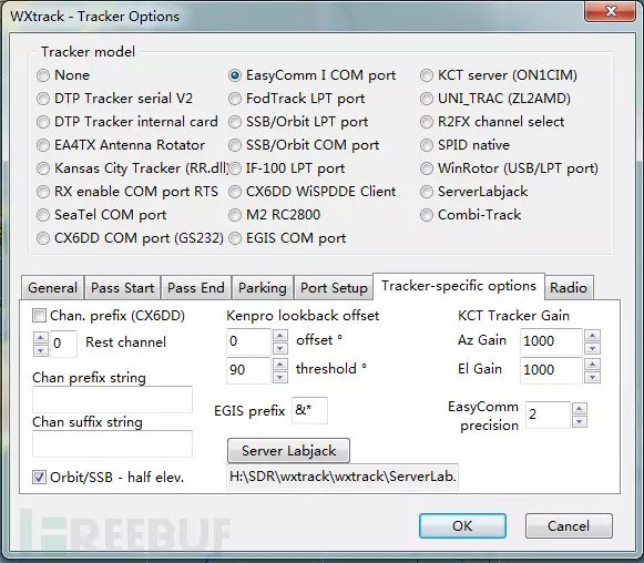
Run the WXtrack software on the computer, find the top menu, and click Tracker–Options to open the antenna tracker settings interface:
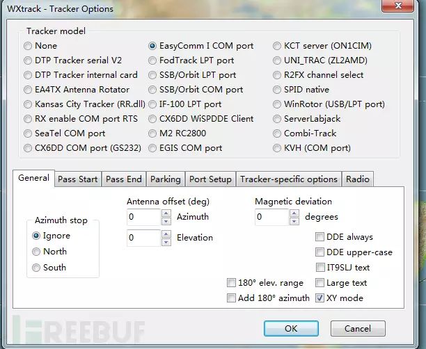
Then we click to select EasyComm I COM port.
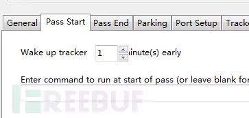
Pass start can be set to 1, meaning the antenna wakes up 1 minute earlier.
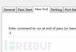
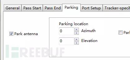
Pass end is the command sent after tracking is complete; we input the reset command for our antenna: “S” or “0” can also be used. Parking means stopping the antenna.
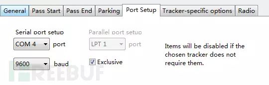
We select Park antenna. Then switch to the Port setup menu, select the corresponding COM port for your Arduino, for example, COM4, and set the baud rate to 9600 as set in the program.
Then enter the Tracker-specific options menu, set EasyComm precision to 2, so that the serial data output by the program retains two decimal points; otherwise, it will be integers, and the overall system’s precision will be very low.
The computer software setup is complete. After adjusting the angles, you can automatically track!
(2) Manual Control
If controlling manually, please open the serial monitor in the Arduino IDE or use other software that can send serial data (various serial debugging tools are fine; please search for them yourself).
Set your Arduino’s corresponding serial port number (available in system management) and set the baud rate to 9600.
When sending angle commands, follow this format: azimuth angle elevation angle (AZ EL), separated by a space, the data can be floating-point or integer. For example, sending: 20 40 means the antenna’s azimuth angle turns to 20 degrees and elevation to 40 degrees.
It is equivalent to: 20.0 40.0. You can input decimal points; if you want finer adjustments, the program’s recognition ability can be precise to 0.1 degrees. If you input only one digit, it will only adjust the azimuth angle, and the elevation angle will be 0.
For example: inputting 20 will turn the antenna to 20 degrees azimuth, and elevation will be 0 degrees. Inputting S or 0 can reset the antenna, meaning both azimuth and elevation angles will be 0 degrees.
Correction Function
This function was the last to be added. Since the antenna has been stored, it has become inconvenient to test, so I haven’t tested it yet; I can only write the code roughly.
Therefore, this function is waiting to be developed later; I don’t know if the code is useful or not. The code during the video recording is different from the current code, so the commands in the serial window of the video are different from the current ones.
After long-term operation, the antenna may lose steps due to motor issues, causing inaccuracies. At this point, you can input commands for calibration. To adjust the antenna simply and clearly, adjust AZ and EL separately.
The command to adjust the azimuth angle is: AA23, meaning the capital letters AA are followed by a number, which can be a floating point or integer. This adjusts the antenna’s current angle to 23 degrees.
The command to adjust the elevation angle is: EE56, with the same principle.
Finally, one important point to mention is that when setting up the antenna, the elevation angle must be level (you can use a level), and the 0-degree azimuth angle must be aligned with true north, not magnetic north.
So figuring out true north is a challenge. I plan to use the direction of the sun at noon local time as true south to determine true north. Note that it is not Beijing time but the current longitude’s time.
You can use a high-precision GPS to obtain accurate local time and then determine true north based on the sun’s projection method. If anyone has a better or more precise method, please share it.
3. Known Defects/Problems
1.During the automatic tracking process, do not close the software to switch to manual tracking; otherwise, the default position where the automatic tracking stops will become the 0-point position.
This also applies after power is cut and restarted.
2. Since this tracking relies on software implementation, it cannot track like national satellite antennas relying on signal gain, so the precision can only meet the needs of amateur radio enthusiasts.
After completing the setup, careful calibration is needed, considering the delays of the program and mechanical devices. We can advance the upper computer’s system time by a few seconds for compensation. The specific adjustments depend on multiple trials to find the best state for your antenna. You can also appropriately reduce acceleration parameters and advance the system time to make the antenna operation smoother.
I look forward to more people improving this.
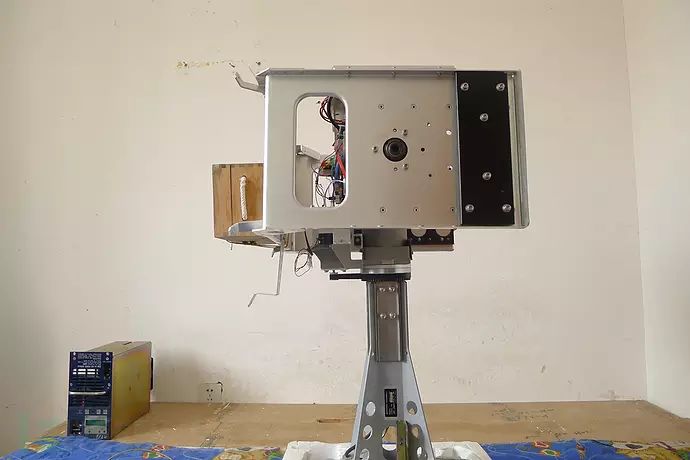
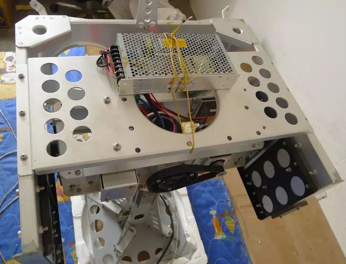
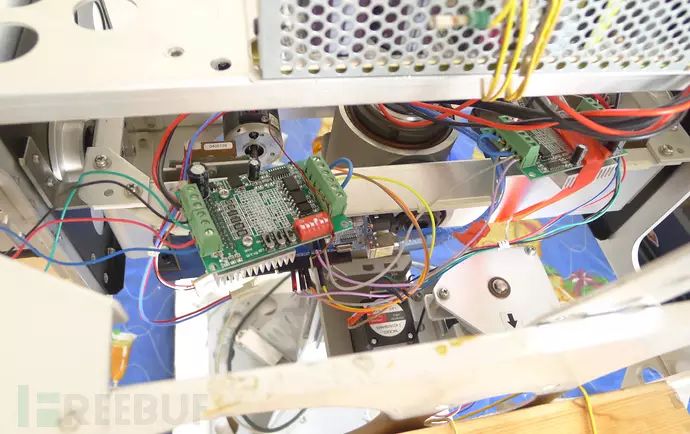
Images of Completed Details:
A red wine box is tied to maintain weight balance; otherwise, the elevation motor will require a lot of force. I will replace the wine box with a parabolic antenna later.
Video of Completed Tests:
The video I made is edited, and many parts are not done well; it may not be very smooth, please forgive me. The video is credited to Rasiel, and the Rasiel account on this website is also me.
Code cloud disk address: http://pan.baidu.com/s/1jHYw80u
* This article is original by: OpenATS, and is part of the FreeBuf original reward program. Reproduction without permission is prohibited.