1 Introduction
Direct Memory Access (DMA) is a component used by the CPU to transfer data from one address space to another without CPU intervention. Once the data transfer is complete, the CPU is notified to process the data. Therefore, using DMA can free up CPU resources during large data transfers. Typical DMA data transfer processes include:
- Memory to Memory, copying between memory locations
- Peripheral to Memory, such as receiving data from UART, SPI, I2C, etc.
- Memory to Peripheral, such as sending data to UART, SPI, I2C, etc.
2 Is DMA Necessary for UART?
UART (Universal Asynchronous Receiver-Transmitter) is a low-speed serial asynchronous communication method suitable for low-speed communication scenarios, typically using baud rates less than or equal to 115200 bps. For communication scenarios with baud rates less than or equal to 115200 bps and small data volumes, using DMA is generally unnecessary, or it does not fully utilize the benefits of DMA.
However, when the data volume is large or the baud rate is increased, it is essential to use DMA to free up CPU resources, as high baud rates can lead to the following issues:
- For sending, using polling may block the thread and consume a lot of CPU resources to transfer data, wasting CPU cycles.
- For sending, using interrupt-based sending does not block the thread but wastes a lot of interrupt resources, causing the CPU to respond to interrupts frequently; at a baud rate of 115200 bps, 11520 bytes are transmitted in 1 second, requiring an interrupt response approximately every 69 microseconds. If the baud rate is increased further, more CPU resources will be consumed.
- For receiving, if traditional interrupt mode is still used, frequent interrupts will also lead to significant CPU resource consumption.
Therefore, in high baud rate scenarios, it is crucial to use DMA for UART.
3 DMA Implementation Methods
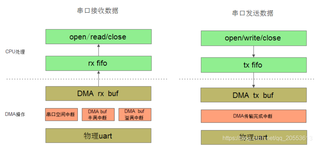
4 Using DMA with STM32 UART
There are many examples and tutorials available online regarding the use of DMA with STM32 UART. The steps, processes, and configurations are generally similar, and their correctness is usually sound. However, these are basic demo examples, which are fine for learning purposes; actual project implementations may lack rigor and could lead to data anomalies when handling large data volumes.
Test Platform:
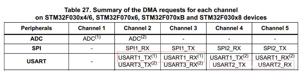
- STM32F030C8T6
- UART1/UART2
- DMA1 Channel2—Channel5
- ST Standard Library
- Clock frequency 48MHz (external 12MHz crystal)
5 UART DMA Reception
5.1 Basic Process
5.2 Related Configuration
Key Steps
[1] Initialize UART
[2] Enable UART DMA reception mode and enable UART idle interrupt
[3] Configure DMA parameters, enable DMA channel buffer half-full (half data transferred) interrupt, and buffer overflow (data transfer complete) interrupt
Why is it necessary to use the DMA channel buffer half-full interrupt?
Many tutorials and examples for UART DMA mode reception typically use “half-full interrupt” + “DMA transfer complete interrupt” to receive data. In reality, this poses a risk: when the DMA transfer is complete, the CPU intervenes to start copying the DMA channel buffer data. If data continues to arrive at the UART during this time, the DMA may continue to transfer data to the buffer, potentially overwriting existing data, as the DMA data transfer is not controlled by the CPU, even if CPU interrupts are disabled.
A more rigorous approach requires implementing a double buffer, where the CPU and DMA each access a separate memory area alternately, known as “ping-pong buffering”. The processing steps should be as follows:
[1] First, the DMA transfers data to buffer1 and notifies the CPU to copy the data from buffer1. [2] Next, the DMA transfers data to buffer2, which does not conflict with the CPU copying data from buffer1. [3] Once the data transfer to buffer2 is complete, the CPU is notified to copy data from buffer2. [4] After completing step three, the DMA returns to execute step one, and this process continues in a loop.
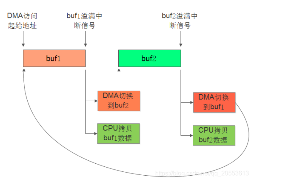
The STM32F0 series DMA does not support a double buffering mechanism (depending on the specific model), but it provides a “half-full interrupt” feature, which generates an interrupt signal when data is transferred to half the size of the buffer. Based on this mechanism, we can implement a double buffering function by simply allocating a larger buffer space.
[1] First, when the DMA completes transferring the first half of the buffer, it generates a “half-full interrupt”, and the CPU copies the first half of the buffer data. [2] Next, the DMA continues transferring data to the second half of the buffer, which does not conflict with the CPU copying data from the first half. [3] Once the second half of the buffer is complete, a “full interrupt” is triggered, and the CPU copies the second half of the buffer data. [4] After completing step three, the DMA returns to execute step one, and this process continues in a loop.
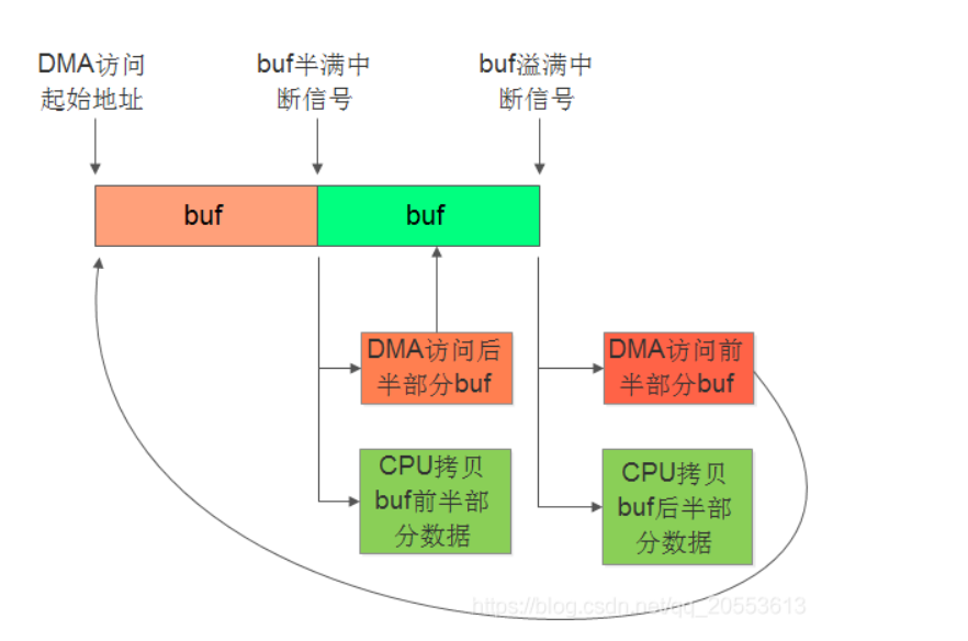
The UART2 DMA mode reception configuration code is as follows, which is generally consistent with the configuration of other peripherals using DMA. Pay attention to the key configurations:
- For UART reception, set the DMA channel working mode to circular mode
- Enable DMA channel reception buffer half-full interrupt and overflow (transfer complete) interrupt
- Clear relevant status flags before starting the DMA channel to prevent data corruption during the first transfer
void bsp_uart2_dmarx_config(uint8_t *mem_addr, uint32_t mem_size) { DMA_InitTypeDef DMA_InitStructure; DMA_DeInit(DMA1_Channel5); DMA_Cmd(DMA1_Channel5, DISABLE); DMA_InitStructure.DMA_PeripheralBaseAddr = (uint32_t)&(USART2->RDR); /* UART2 receive data address */ DMA_InitStructure.DMA_MemoryBaseAddr = (uint32_t)mem_addr; /* Receive buffer */ DMA_InitStructure.DMA_DIR = DMA_DIR_PeripheralSRC; /* Transfer direction: Peripheral to Memory */ DMA_InitStructure.DMA_BufferSize = mem_size; /* Receive buffer size */ DMA_InitStructure.DMA_PeripheralInc = DMA_PeripheralInc_Disable; DMA_InitStructure.DMA_MemoryInc = DMA_MemoryInc_Enable; DMA_InitStructure.DMA_PeripheralDataSize = DMA_PeripheralDataSize_Byte; DMA_InitStructure.DMA_MemoryDataSize = DMA_MemoryDataSize_Byte; DMA_InitStructure.DMA_Mode = DMA_Mode_Circular; /* Circular mode */ DMA_InitStructure.DMA_Priority = DMA_Priority_VeryHigh; DMA_InitStructure.DMA_M2M = DMA_M2M_Disable; DMA_Init(DMA1_Channel5, &DMA_InitStructure); DMA_ITConfig(DMA1_Channel5, DMA_IT_TC|DMA_IT_HT|DMA_IT_TE, ENABLE); /* Enable DMA half-full, overflow, error interrupts */ DMA_ClearFlag(DMA1_IT_TC5); /* Clear relevant status flags */ DMA_ClearFlag(DMA1_IT_HT5); DMA_Cmd(DMA1_Channel5, ENABLE); }DMA Error Interrupt
<span><span>"DMA_IT_TE"</span></span>is generally used for early debugging to check the number of DMA errors. This interrupt can be disabled in the released software.
5.3 Reception Processing
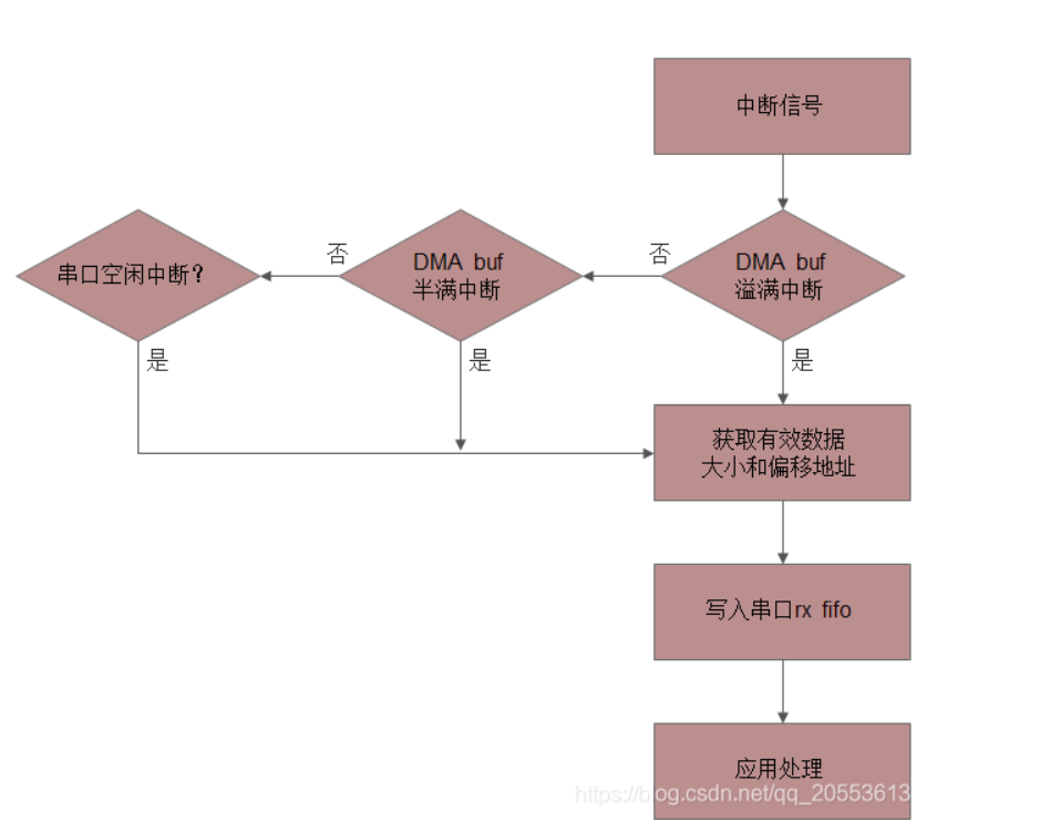
Based on the above mechanism description, there are three interrupt scenarios in DMA mode reception of UART data that require the CPU to copy the buffer data to FIFO:
- DMA channel buffer overflow (transfer complete) scenario
- DMA channel buffer half-full scenario
- UART idle interrupt scenario
The first two scenarios have been described in previous articles. The UART idle interrupt indicates that after data transmission is complete, the UART detects that no data has arrived for a certain period, triggering an interrupt signal.
5.3.1 Received Data Size
The data transmission process is random, and the data size is also variable, leading to several situations:
- The data is exactly an integer multiple of the DMA reception buffer size, which is the ideal state.
- The data volume is less than the DMA reception buffer or less than half of the reception buffer, which will trigger the UART idle interrupt.
Therefore, we need to calculate the current received data size based on the <span><span>"DMA channel buffer size", "DMA channel buffer remaining size", "last received total data size"</span></span>.
/* Get the remaining size of the DMA channel reception buffer */ uint16_t DMA_GetCurrDataCounter(DMA_Channel_TypeDef* DMAy_Channelx);DMA Channel Buffer Overflow Scenario Calculation
Received data size = DMA channel buffer size - last received total data sizeDMA channel buffer overflow interrupt handling function:
void uart_dmarx_done_isr(uint8_t uart_id) { uint16_t recv_size; recv_size = s_uart_dev[uart_id].dmarx_buf_size - s_uart_dev[uart_id].last_dmarx_size; fifo_write(&s_uart_dev[uart_id].rx_fifo, (const uint8_t *)&s_uart_dev[uart_id].dmarx_buf[s_uart_dev[uart_id].last_dmarx_size], recv_size); s_uart_dev[uart_id].last_dmarx_size = 0; }DMA Channel Buffer Half-Full Scenario Calculation
Received data size = DMA channel total received data size - last received total data size DMA channel total received data size = DMA channel buffer size - DMA channel buffer remaining sizeDMA channel buffer half-full interrupt handling function:
void uart_dmarx_half_done_isr(uint8_t uart_id) { uint16_t recv_total_size; uint16_t recv_size; if (uart_id == 0) { recv_total_size = s_uart_dev[uart_id].dmarx_buf_size - bsp_uart1_get_dmarx_buf_remain_size(); } else if (uart_id == 1) { recv_total_size = s_uart_dev[uart_id].dmarx_buf_size - bsp_uart2_get_dmarx_buf_remain_size(); } recv_size = recv_total_size - s_uart_dev[uart_id].last_dmarx_size; fifo_write(&s_uart_dev[uart_id].rx_fifo, (const uint8_t *)&s_uart_dev[uart_id].dmarx_buf[s_uart_dev[uart_id].last_dmarx_size], recv_size); s_uart_dev[uart_id].last_dmarx_size = recv_total_size; /* Record total received data size */ }UART Idle Interrupt Scenario Calculation
The calculation of received data in the UART idle interrupt scenario is the same as that in the “DMA channel buffer half-full scenario”.
UART idle interrupt handling function:
void uart_dmarx_idle_isr(uint8_t uart_id) { uint16_t recv_total_size; uint16_t recv_size; if (uart_id == 0) { recv_total_size = s_uart_dev[uart_id].dmarx_buf_size - bsp_uart1_get_dmarx_buf_remain_size(); } else if (uart_id == 1) { recv_total_size = s_uart_dev[uart_id].dmarx_buf_size - bsp_uart2_get_dmarx_buf_remain_size(); } recv_size = recv_total_size - s_uart_dev[uart_id].last_dmarx_size; s_UartTxRxCount[uart_id*2+1] += recv_size; fifo_write(&s_uart_dev[uart_id].rx_fifo, (const uint8_t *)&s_uart_dev[uart_id].dmarx_buf[s_uart_dev[uart_id].last_dmarx_size], recv_size); s_uart_dev[uart_id].last_dmarx_size = recv_total_size; }Note: In the UART idle interrupt handling function, in addition to copying data to the UART receive FIFO, special processing can be added, such as marking the completion of UART data transmission or handling variable-length data.
5.3.2 Received Data Offset Address
To copy valid data to the FIFO, it is necessary to know the valid data size and the offset address where the data is stored in the DMA reception buffer. The valid data offset address can be recorded as the last received total size, which can be cleared in the DMA channel buffer overflow interrupt handling function, as the next data will be stored from the beginning of the buffer.
In the DMA channel buffer overflow interrupt handling function, clear the data offset address:
void uart_dmarx_done_isr(uint8_t uart_id) { /* todo */ s_uart_dev[uart_id].last_dmarx_size = 0; }5.4 Application Method for Reading UART Data
After the previous processing steps, the UART data has been copied to the receive FIFO, and the application task only needs to retrieve data from the FIFO for processing. The prerequisite is that the processing efficiency must be greater than the DMA data reception transfer efficiency; otherwise, data loss or overwriting may occur.
6 UART DMA Transmission
6.1 Basic Process
6.2 Related Configuration
Key Steps
[1] Initialize UART
[2] Enable UART DMA transmission mode
[3] Configure the DMA transmission channel; this step does not need to be set during initialization, but only when there is data to be sent
The UART2 DMA mode transmission configuration code is as follows, which is generally consistent with the configuration of other peripherals using DMA. Pay attention to the key configurations:
- For UART transmission, set the DMA channel working mode to normal mode (single transfer mode), and reconfigure the DMA each time data needs to be sent
- Enable DMA channel transfer complete interrupt to handle necessary tasks, such as clearing the transmission status and starting the next transmission
- Clear relevant status flags before starting the DMA channel to prevent data corruption during the first transfer
void bsp_uart2_dmatx_config(uint8_t *mem_addr, uint32_t mem_size) { DMA_InitTypeDef DMA_InitStructure; DMA_DeInit(DMA1_Channel4); DMA_Cmd(DMA1_Channel4, DISABLE); DMA_InitStructure.DMA_PeripheralBaseAddr = (uint32_t)&(USART2->TDR); /* UART2 send data address */ DMA_InitStructure.DMA_MemoryBaseAddr = (uint32_t)mem_addr; /* Send data buffer */ DMA_InitStructure.DMA_DIR = DMA_DIR_PeripheralDST; /* Transfer direction: Memory to Peripheral */ DMA_InitStructure.DMA_BufferSize = mem_size; /* Send data buffer size */ DMA_InitStructure.DMA_PeripheralInc = DMA_PeripheralInc_Disable; DMA_InitStructure.DMA_MemoryInc = DMA_MemoryInc_Enable; DMA_InitStructure.DMA_PeripheralDataSize = DMA_PeripheralDataSize_Byte; DMA_InitStructure.DMA_MemoryDataSize = DMA_MemoryDataSize_Byte; DMA_InitStructure.DMA_Mode = DMA_Mode_Normal; /* Single transfer mode */ DMA_InitStructure.DMA_Priority = DMA_Priority_High; DMA_InitStructure.DMA_M2M = DMA_M2M_Disable; DMA_Init(DMA1_Channel4, &DMA_InitStructure); DMA_ITConfig(DMA1_Channel4, DMA_IT_TC|DMA_IT_TE, ENABLE); /* Enable transfer complete interrupt and error interrupt */ DMA_ClearFlag(DMA1_IT_TC4); /* Clear transmission complete flag */ DMA_Cmd(DMA1_Channel4, ENABLE); /* Start DMA transmission */ }6.3 Transmission Processing
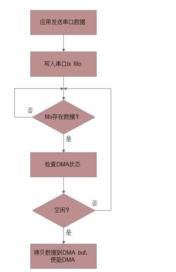
The data to be sent via UART is stored in the transmission FIFO. The transmission processing function needs to continuously check whether there is data in the transmission FIFO; if there is, it copies that data to the DMA transmission buffer and then starts the DMA transfer. The prerequisite is to wait for the previous DMA transfer to complete, which is indicated by the DMA transfer complete interrupt signal <span><span>"DMA_IT_TC"</span></span>.
UART Transmission Processing Function:
void uart_poll_dma_tx(uint8_t uart_id) { uint16_t size = 0; if (0x01 == s_uart_dev[uart_id].status) { return; } size = fifo_read(&s_uart_dev[uart_id].tx_fifo, s_uart_dev[uart_id].dmatx_buf, s_uart_dev[uart_id].dmatx_buf_size); if (size != 0) { s_UartTxRxCount[uart_id*2+0] += size; if (uart_id == 0) { s_uart_dev[uart_id].status = 0x01; /* DMA transmission status */ bsp_uart1_dmatx_config(s_uart_dev[uart_id].dmatx_buf, size); } else if (uart_id == 1) { s_uart_dev[uart_id].status = 0x01; /* DMA transmission status, must set before enabling DMA transfer, otherwise DMA may have already transferred and entered interrupt */ bsp_uart2_dmatx_config(s_uart_dev[uart_id].dmatx_buf, size); } }}- Note the transmission status flag; it must be set to “transmission status” before starting the DMA transfer. If the steps are reversed, when the data volume is small, the DMA transfer time is short, and the
<span><span>"DMA_IT_TC"</span></span>interrupt may execute before the “transmission status flag is set”, leading to a misjudgment that the DMA is still processing the transmission status (the transmission flag cannot be cleared).
Note: Regarding the DMA transmission start function, some blog articles describe that it is sufficient to change the size of the DMA transmission buffer; however, testing has shown that this method works for small data volumes but fails for larger data volumes and does not trigger the DMA transmission complete interrupt. Therefore, a reliable method is to reconfigure all DMA channel parameters each time the DMA transmission is started. This step only involves configuring registers and does not consume much CPU execution time.
DMA Transmission Complete Interrupt Handling Function:
void uart_dmatx_done_isr(uint8_t uart_id) { s_uart_dev[uart_id].status = 0; /* Clear DMA transmission status flag */ }The above UART transmission processing function can be called in several situations:
- Called by the main thread task, provided that the thread is not blocked by other tasks; otherwise, it may lead to FIFO overflow.
void thread(void) { uart_poll_dma_tx(DEV_UART1); uart_poll_dma_tx(DEV_UART2); }- Called in a timer interrupt
void TIMx_IRQHandler(void) { uart_poll_dma_tx(DEV_UART1); uart_poll_dma_tx(DEV_UART2); }- Called in the DMA channel transmission complete interrupt
void DMA1_Channel4_5_IRQHandler(void) { if (DMA_GetITStatus(DMA1_IT_TC4)) { UartDmaSendDoneIsr(UART_2); DMA_ClearFlag(DMA1_FLAG_TC4); uart_poll_dma_tx(DEV_UART2); }}How much data to copy to the DMA transmission buffer each time:
This issue is related to the specific application scenario, and the principle to follow is: as long as the amount of data in the transmission FIFO is greater than or equal to the size of the DMA transmission buffer, the DMA transmission buffer should be filled, and then the DMA transfer should be started to fully utilize the DMA performance. Therefore, it is necessary to balance the efficiency of each DMA transfer and the real-time nature of the UART data stream, considering several implementation approaches:
- Periodically query the transmission FIFO data to start the DMA transfer, fully utilizing DMA transmission efficiency, but potentially reducing the real-time nature of the UART data stream.
- Real-time query of transmission FIFO data with timeout handling, which is the ideal method.
- Handle in the DMA transmission complete interrupt to ensure a real-time continuous data stream.
7 UART Device
7.1 Data Structure
/* UART device data structure */ typedef struct { uint8_t status; /* Transmission status */ _fifo_t tx_fifo; /* Transmission FIFO */ _fifo_t rx_fifo; /* Reception FIFO */ uint8_t *dmarx_buf; /* DMA reception buffer */ uint16_t dmarx_buf_size; /* DMA reception buffer size */ uint8_t *dmatx_buf; /* DMA transmission buffer */ uint16_t dmatx_buf_size; /* DMA transmission buffer size */ uint16_t last_dmarx_size; /* Last DMA received data size */ } uart_device_t;7.2 External Interfaces
/* UART registration initialization function */ void uart_device_init(uint8_t uart_id) { if (uart_id == 1) { /* Configure UART2 transmission and reception FIFO */ fifo_register(&s_uart_dev[uart_id].tx_fifo, &s_uart2_tx_buf[0], sizeof(s_uart2_tx_buf), fifo_lock, fifo_unlock); fifo_register(&s_uart_dev[uart_id].rx_fifo, &s_uart2_rx_buf[0], sizeof(s_uart2_rx_buf), fifo_lock, fifo_unlock); /* Configure UART2 DMA transmission and reception buffer */ s_uart_dev[uart_id].dmarx_buf = &s_uart2_dmarx_buf[0]; s_uart_dev[uart_id].dmarx_buf_size = sizeof(s_uart2_dmarx_buf); s_uart_dev[uart_id].dmatx_buf = &s_uart2_dmatx_buf[0]; s_uart_dev[uart_id].dmatx_buf_size = sizeof(s_uart2_dmatx_buf); bsp_uart2_dmarx_config(s_uart_dev[uart_id].dmarx_buf, sizeof(s_uart2_dmarx_buf)); s_uart_dev[uart_id].status = 0; }} /* UART transmission function */ uint16_t uart_write(uint8_t uart_id, const uint8_t *buf, uint16_t size) { return fifo_write(&s_uart_dev[uart_id].tx_fifo, buf, size); } /* UART reading function */ uint16_t uart_read(uint8_t uart_id, uint8_t *buf, uint16_t size) { return fifo_read(&s_uart_dev[uart_id].rx_fifo, buf, size); }8 Complete Source Code
Code repository: https://github.com/Prry/stm32f0-uart-dma
Click “Read the original text” at the end to go directly.
UART & DMA low-level configuration:
#include <stddef.h> #include <stdint.h> #include <stdbool.h> #include "stm32f0xx.h" #include "bsp_uart.h" /** * @brief * @param * @retval */ static void bsp_uart1_gpio_init(void) { GPIO_InitTypeDef GPIO_InitStructure; #if 0 RCC_AHBPeriphClockCmd(RCC_AHBPeriph_GPIOB, ENABLE); GPIO_PinAFConfig(GPIOB, GPIO_PinSource6, GPIO_AF_0); GPIO_PinAFConfig(GPIOB, GPIO_PinSource7, GPIO_AF_0); GPIO_InitStructure.GPIO_Pin = GPIO_Pin_6 | GPIO_Pin_7; GPIO_InitStructure.GPIO_Mode = GPIO_Mode_AF; GPIO_InitStructure.GPIO_OType = GPIO_OType_PP; GPIO_InitStructure.GPIO_Speed = GPIO_Speed_Level_3; GPIO_InitStructure.GPIO_PuPd = GPIO_PuPd_UP; GPIO_Init(GPIOB, &GPIO_InitStructure); #else RCC_AHBPeriphClockCmd(RCC_AHBPeriph_GPIOA, ENABLE); GPIO_PinAFConfig(GPIOB, GPIO_PinSource9, GPIO_AF_1); GPIO_PinAFConfig(GPIOB, GPIO_PinSource10, GPIO_AF_1); GPIO_InitStructure.GPIO_Pin = GPIO_Pin_9 | GPIO_Pin_10; GPIO_InitStructure.GPIO_Mode = GPIO_Mode_AF; GPIO_InitStructure.GPIO_OType = GPIO_OType_PP; GPIO_InitStructure.GPIO_Speed = GPIO_Speed_Level_3; GPIO_InitStructure.GPIO_PuPd = GPIO_PuPd_UP; GPIO_Init(GPIOA, &GPIO_InitStructure); #endif } /** * @brief * @param * @retval */ static void bsp_uart2_gpio_init(void) { GPIO_InitTypeDef GPIO_InitStructure; RCC_AHBPeriphClockCmd(RCC_AHBPeriph_GPIOB, ENABLE); GPIO_PinAFConfig(GPIOA, GPIO_PinSource2, GPIO_AF_1); GPIO_PinAFConfig(GPIOA, GPIO_PinSource3, GPIO_AF_1); GPIO_InitStructure.GPIO_Pin = GPIO_Pin_2 | GPIO_Pin_3; GPIO_InitStructure.GPIO_Mode = GPIO_Mode_AF; GPIO_InitStructure.GPIO_OType = GPIO_OType_PP; GPIO_InitStructure.GPIO_Speed = GPIO_Speed_10MHz; GPIO_InitStructure.GPIO_PuPd = GPIO_PuPd_UP; GPIO_Init(GPIOA, &GPIO_InitStructure); } /** * @brief * @param * @retval */ void bsp_uart1_init(void) { USART_InitTypeDef USART_InitStructure; NVIC_InitTypeDef NVIC_InitStructure; bsp_uart1_gpio_init(); /* Enable UART and DMA clocks */ RCC_AHBPeriphClockCmd(RCC_AHBPeriph_DMA1, ENABLE); RCC_APB2PeriphClockCmd(RCC_APB2Periph_USART1, ENABLE); USART_InitStructure.USART_BaudRate = 57600; USART_InitStructure.USART_WordLength = USART_WordLength_8b; USART_InitStructure.USART_StopBits = USART_StopBits_1; USART_InitStructure.USART_Parity = USART_Parity_No; USART_InitStructure.USART_HardwareFlowControl = USART_HardwareFlowControl_None; USART_InitStructure.USART_Mode = USART_Mode_Rx | USART_Mode_Tx; USART_Init(USART1, &USART_InitStructure); USART_ITConfig(USART1, USART_IT_IDLE, ENABLE); /* Enable idle interrupt */ USART_OverrunDetectionConfig(USART1, USART_OVRDetection_Disable); USART_Cmd(USART1, ENABLE); USART_DMACmd(USART1, USART_DMAReq_Rx|USART_DMAReq_Tx, ENABLE); /* Enable DMA reception and transmission */ /* UART Interrupt */ NVIC_InitStructure.NVIC_IRQChannel = USART1_IRQn; NVIC_InitStructure.NVIC_IRQChannelPriority = 2; NVIC_InitStructure.NVIC_IRQChannelCmd = ENABLE; NVIC_Init(&NVIC_InitStructure); /* DMA Interrupt */ NVIC_InitStructure.NVIC_IRQChannel = DMA1_Channel2_3_IRQn; NVIC_InitStructure.NVIC_IRQChannelPriority = 0; NVIC_InitStructure.NVIC_IRQChannelCmd = ENABLE; NVIC_Init(&NVIC_InitStructure); } /** * @brief * @param * @retval */ void bsp_uart2_init(void) { USART_InitTypeDef USART_InitStructure; NVIC_InitTypeDef NVIC_InitStructure; bsp_uart2_gpio_init(); /* Enable UART and DMA clocks */ RCC_AHBPeriphClockCmd(RCC_AHBPeriph_DMA1, ENABLE); RCC_APB1PeriphClockCmd(RCC_APB1Periph_USART2, ENABLE); USART_InitStructure.USART_BaudRate = 57600; USART_InitStructure.USART_WordLength = USART_WordLength_8b; USART_InitStructure.USART_StopBits = USART_StopBits_1; USART_InitStructure.USART_Parity = USART_Parity_No; USART_InitStructure.USART_HardwareFlowControl = USART_HardwareFlowControl_None; USART_InitStructure.USART_Mode = USART_Mode_Rx | USART_Mode_Tx; USART_Init(USART2, &USART_InitStructure); USART_ITConfig(USART2, USART_IT_IDLE, ENABLE); /* Enable idle interrupt */ USART_OverrunDetectionConfig(USART2, USART_OVRDetection_Disable); USART_Cmd(USART2, ENABLE); USART_DMACmd(USART2, USART_DMAReq_Rx|USART_DMAReq_Tx, ENABLE); /* Enable DMA reception and transmission */ /* UART Interrupt */ NVIC_InitStructure.NVIC_IRQChannel = USART2_IRQn; NVIC_InitStructure.NVIC_IRQChannelPriority = 2; NVIC_InitStructure.NVIC_IRQChannelCmd = ENABLE; NVIC_Init(&NVIC_InitStructure); /* DMA Interrupt */ NVIC_InitStructure.NVIC_IRQChannel = DMA1_Channel4_5_IRQn; NVIC_InitStructure.NVIC_IRQChannelPriority = 0; NVIC_InitStructure.NVIC_IRQChannelCmd = ENABLE; NVIC_Init(&NVIC_InitStructure); } void bsp_uart1_dmatx_config(uint8_t *mem_addr, uint32_t mem_size) { DMA_InitTypeDef DMA_InitStructure; DMA_DeInit(DMA1_Channel2); DMA_Cmd(DMA1_Channel2, DISABLE); DMA_InitStructure.DMA_PeripheralBaseAddr = (uint32_t)&(USART1->TDR); DMA_InitStructure.DMA_MemoryBaseAddr = (uint32_t)mem_addr; DMA_InitStructure.DMA_DIR = DMA_DIR_PeripheralDST; /* Transfer direction: Memory to Peripheral */ DMA_InitStructure.DMA_BufferSize = mem_size; DMA_InitStructure.DMA_PeripheralInc = DMA_PeripheralInc_Disable; DMA_InitStructure.DMA_MemoryInc = DMA_MemoryInc_Enable; DMA_InitStructure.DMA_PeripheralDataSize = DMA_PeripheralDataSize_Byte; DMA_InitStructure.DMA_MemoryDataSize = DMA_MemoryDataSize_Byte; DMA_InitStructure.DMA_Mode = DMA_Mode_Normal; DMA_InitStructure.DMA_Priority = DMA_Priority_High; DMA_InitStructure.DMA_M2M = DMA_M2M_Disable; DMA_Init(DMA1_Channel2, &DMA_InitStructure); DMA_ITConfig(DMA1_Channel2, DMA_IT_TC|DMA_IT_TE, ENABLE); DMA_ClearFlag(DMA1_IT_TC2); /* Clear transmission complete flag */ DMA_Cmd(DMA1_Channel2, ENABLE); } void bsp_uart1_dmarx_config(uint8_t *mem_addr, uint32_t mem_size) { DMA_InitTypeDef DMA_InitStructure; DMA_DeInit(DMA1_Channel3); DMA_Cmd(DMA1_Channel3, DISABLE); DMA_InitStructure.DMA_PeripheralBaseAddr = (uint32_t)&(USART1->RDR); DMA_InitStructure.DMA_MemoryBaseAddr = (uint32_t)mem_addr; DMA_InitStructure.DMA_DIR = DMA_DIR_PeripheralSRC; /* Transfer direction: Peripheral to Memory */ DMA_InitStructure.DMA_BufferSize = mem_size; DMA_InitStructure.DMA_PeripheralInc = DMA_PeripheralInc_Disable; DMA_InitStructure.DMA_MemoryInc = DMA_MemoryInc_Enable; DMA_InitStructure.DMA_PeripheralDataSize = DMA_PeripheralDataSize_Byte; DMA_InitStructure.DMA_MemoryDataSize = DMA_MemoryDataSize_Byte; DMA_InitStructure.DMA_Mode = DMA_Mode_Circular; DMA_InitStructure.DMA_Priority = DMA_Priority_VeryHigh; DMA_InitStructure.DMA_M2M = DMA_M2M_Disable; DMA_Init(DMA1_Channel3, &DMA_InitStructure); DMA_ITConfig(DMA1_Channel3, DMA_IT_TC|DMA_IT_HT|DMA_IT_TE, ENABLE);/* Enable DMA half-full, full, error interrupts */ DMA_ClearFlag(DMA1_IT_TC3); DMA_ClearFlag(DMA1_IT_HT3); DMA_Cmd(DMA1_Channel3, ENABLE); } uint16_t bsp_uart1_get_dmarx_buf_remain_size(void) { return DMA_GetCurrDataCounter(DMA1_Channel3); /* Get remaining size of DMA reception buffer */ } void bsp_uart2_dmatx_config(uint8_t *mem_addr, uint32_t mem_size) { DMA_InitTypeDef DMA_InitStructure; DMA_DeInit(DMA1_Channel4); DMA_Cmd(DMA1_Channel4, DISABLE); DMA_InitStructure.DMA_PeripheralBaseAddr = (uint32_t)&(USART2->TDR); DMA_InitStructure.DMA_MemoryBaseAddr = (uint32_t)mem_addr; DMA_InitStructure.DMA_DIR = DMA_DIR_PeripheralDST; /* Transfer direction: Memory to Peripheral */ DMA_InitStructure.DMA_BufferSize = mem_size; DMA_InitStructure.DMA_PeripheralInc = DMA_PeripheralInc_Disable; DMA_InitStructure.DMA_MemoryInc = DMA_MemoryInc_Enable; DMA_InitStructure.DMA_PeripheralDataSize = DMA_PeripheralDataSize_Byte; DMA_InitStructure.DMA_MemoryDataSize = DMA_MemoryDataSize_Byte; DMA_InitStructure.DMA_Mode = DMA_Mode_Normal; DMA_InitStructure.DMA_Priority = DMA_Priority_High; DMA_InitStructure.DMA_M2M = DMA_M2M_Disable; DMA_Init(DMA1_Channel4, &DMA_InitStructure); DMA_ITConfig(DMA1_Channel4, DMA_IT_TC|DMA_IT_TE, ENABLE); DMA_ClearFlag(DMA1_IT_TC4); /* Clear transmission complete flag */ DMA_Cmd(DMA1_Channel4, ENABLE); } void bsp_uart2_dmarx_config(uint8_t *mem_addr, uint32_t mem_size) { DMA_InitTypeDef DMA_InitStructure; DMA_DeInit(DMA1_Channel5); DMA_Cmd(DMA1_Channel5, DISABLE); DMA_InitStructure.DMA_PeripheralBaseAddr = (uint32_t)&(USART2->RDR); DMA_InitStructure.DMA_MemoryBaseAddr = (uint32_t)mem_addr; DMA_InitStructure.DMA_DIR = DMA_DIR_PeripheralSRC; /* Transfer direction: Peripheral to Memory */ DMA_InitStructure.DMA_BufferSize = mem_size; DMA_InitStructure.DMA_PeripheralInc = DMA_PeripheralInc_Disable; DMA_InitStructure.DMA_MemoryInc = DMA_MemoryInc_Enable; DMA_InitStructure.DMA_PeripheralDataSize = DMA_PeripheralDataSize_Byte; DMA_InitStructure.DMA_MemoryDataSize = DMA_MemoryDataSize_Byte; DMA_InitStructure.DMA_Mode = DMA_Mode_Circular; DMA_InitStructure.DMA_Priority = DMA_Priority_VeryHigh; DMA_InitStructure.DMA_M2M = DMA_M2M_Disable; DMA_Init(DMA1_Channel5, &DMA_InitStructure); DMA_ITConfig(DMA1_Channel5, DMA_IT_TC|DMA_IT_HT|DMA_IT_TE, ENABLE);/* Enable DMA half-full, full, error interrupts */ DMA_ClearFlag(DMA1_IT_TC5); DMA_ClearFlag(DMA1_IT_HT5); DMA_Cmd(DMA1_Channel5, ENABLE); } uint16_t bsp_uart2_get_dmarx_buf_remain_size(void) { return DMA_GetCurrDataCounter(DMA1_Channel5); /* Get remaining size of DMA reception buffer */ }Stress Test:
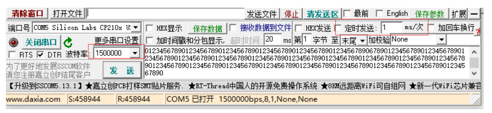
- At a baud rate of 1.5 Mbps, the serial assistant sends 1k bytes of data every millisecond, and the STM32F0 receives the data via DMA, then sends it back to the serial assistant via DMA, with no pressure.
- At a baud rate of 1.5 Mbps, large file transmission tests can be conducted, saving the received data as a file and comparing it with the source file.
- High baud rate testing for UART requires that both the USB to TTL tool and the serial assistant support it; recommended USB to TTL tools with CP2102 or FT232 chips.
Acuity.
https://blog.csdn.net/qq_20553613