1. IntroductionThe IWDG, short for Independent Watchdog, is essentially a counter that can generate a system reset signal.Features: (1) A decrementing counter. (2) The clock is provided by an independent RC oscillator (internal LSI) and can operate in both standby and stop modes. Once the watchdog is activated, it generates a reset when the decrementing counter counts down to 0x000. (3) The watchdog must be fed before the counter decrements to 0, which means reloading the counter value to prevent a system reset.Function: (1) Abnormalities: External electromagnetic interference or internal system (hardware) anomalies can cause the program to run erratically, such as getting stuck in an abnormal infinite loop. (2) Application: In products that require high stability and have lower time precision requirements.2. IWDG Block DiagramAs shown in the figure below, the IWDG has four registers: prescaler register, status register, reload register, and key register.LSI is the internal low-speed clock, which is automatically enabled after the IWDG is activated. It passes through a programmable prescaler,which is configured via IWDG_PR.IWDG_SRindicates whether the prescaler value and decrementing counter are being updated, and the specific usage depends on the register.IWDG_RLR is used to configure the reload value, which will be loaded into the decrementing counter when it decrements to 0.IWDG_KR is the control register for the IWDG, controlling the enablement of the IWDG, disabling write protection for PR and RLR registers, and feeding the watchdog.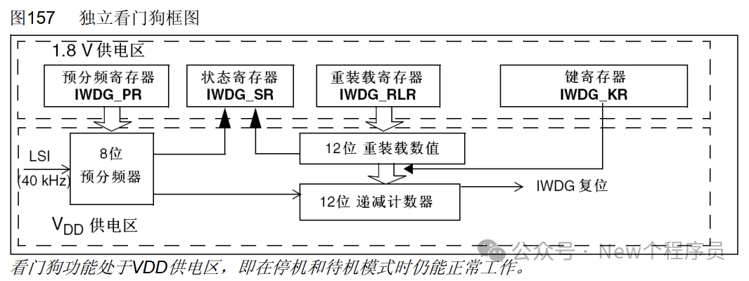
3. IWDG Registers
1. Key Register (IWDG_KR)
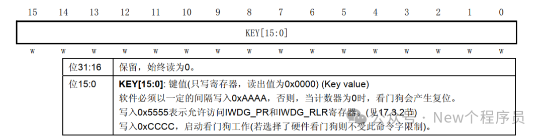
This is a write-only register that only uses the lower 16 bits. Writing 0xAAAA feeds the watchdog within the specified time, writing 0x5555 disables write protection for the PR and RLR registers, and writing 0xCCCC starts the watchdog.
2. Prescaler Register (IWDG_PR)
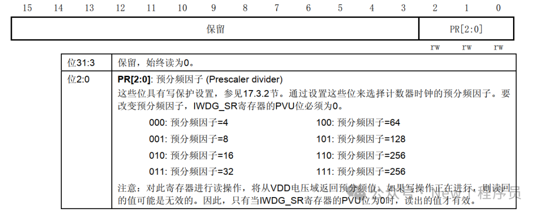
This is a read-write register that only uses the lower 3 bits. Both values 111 and 110 correspond to 256, as confirmed in the English manual.
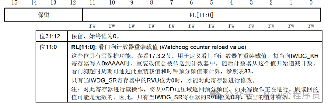
 3. Reload Register (IWDG_RLR) This is a read-write register that only uses the lower 12 bits,
| Every time 0xAAAA is written to the IWDG_KR register, the reload value is transferred to the counter. |
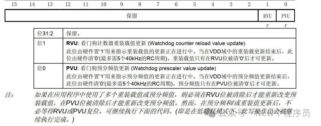
 4. Status Register (IWDG_SR)
This is a read-only register that only uses the lower 2 bits. It must be cleared before the RVU bit can be changed, and the PVU bit must be cleared before the prescaler value can be changed.
4. IWDG Overflow Time Calculation
Calculation formula: Tout=(psc*RLR)/FIWDG.
Tout is the watchdog overflow time,
FWIDG is the clock source frequency of the watchdog,
psc is the watchdog prescaler coefficient,
RLR is the watchdog reload value.
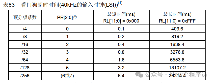
The table below shows the shortest and longest times calculated based on different prescaler coefficients, measured in ms.
The shortest time calculation is when RLR is 1, for example, with a prescaler coefficient of 4, Tout=4/40000=0.1ms.
The longest time calculation is when RLR is 4096, for example, with a prescaler coefficient of 4, Tout=4*4096/40000=409.6ms.
Other time calculations are similar.
5. Register Configuration Steps
1. Enable the IWDG by writing 0xCCCC to the key register (IWDG_KR).
2. Enable register access to PR and RLR by writing 0x5555 to the key register (IWDG_KR).
3. Configure the prescaler by programming the prescaler register (IWDG_PR) with a value from 0 to 7.
4. Perform a write operation to the reload register (IWDG_RLR).
5. Wait for the register to update (IWDG_SR = 0x0000 0000).
6. Refresh the counter value to the value of IWDG_RLR (write 0xAAAA to IWDG_KR).
6. Conclusion
This is a brief introduction to the IWDG. Using STM32CubeMx software will automatically generate the above content. If there are any errors or good ideas, please leave a comment, and I will make the necessary corrections.