UART
The serial port is asynchronous (does not transmit clock-related data). When two devices communicate using the serial port, they must first agree on a data transmission rate, and the clock frequencies of both devices must be close to this rate. A significant difference in clock frequency on either side will lead to data transmission confusion.
1 Hardware Connection
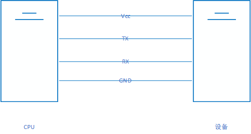
UART can be understood as a one-wire bus that can complete data transmission. The connection diagram is as follows:
-
VCC is used to provide power to the device. If the device has its own power supply, this can be omitted.
-
TX, as the name suggests, is the CPU sending data to the device – corresponding to the device’s RX.
-
RX, as the name suggests, is the CPU receiving data from the device – corresponding to the device’s TX.
-
GND is the ground wire, which is essential for embedded systems. Without GND, how can there be a reference signal?
2 Software Communication Protocol
As a type of asynchronous serial communication protocol, the working principle of UART is to transmit each character of data bit by bit. There are many other serial communication protocols; details can be found in this serial bus protocol.
The UART protocol definition is as follows: 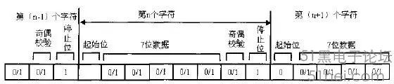
The meanings of each bit are as follows:
-
Start Bit: A logical “0” signal is sent first, indicating the beginning of character transmission.
-
Data Bits: Immediately following the start bit. The number of data bits can be 4, 5, 6, 7, 8, etc., forming a character. Typically, ASCII code is used. Transmission starts from the least significant bit, synchronized by the clock.
-
Parity Bit: Adding this bit to the data bits ensures that the number of “1” bits is even (even parity) or odd (odd parity), thus verifying the correctness of data transmission.
-
Stop Bit: This is a character data end marker. It can be 1, 1.5, or 2 bits high. Since data is timed on the transmission line, and each device has its own clock, small synchronization differences can occur between two devices during communication. Therefore, the stop bit not only indicates the end of transmission but also provides an opportunity for the computer to correct clock synchronization. The more stop bits used, the greater the tolerance for clock synchronization differences, but the data transmission rate also decreases.
-
Idle Bit: Remains in a logical “1” state, indicating that there is currently no data being transmitted on the line.
-
Baud Rate: This is the metric for measuring data transmission speed. It indicates the number of symbols transmitted per second. The amount of information (number of bits) represented by a symbol is related to the order of the symbol. For example, if the data transmission rate is 120 characters/second, using 256-order symbols where each symbol represents 8 bits, the baud rate would be 120 baud, and the bit rate is 120*8=960 bit/s. These two concepts are easily confused.
-
Baud Rate Calculation Example
-
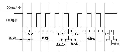
As shown in the figure:
-
-
The first byte’s 10 bits (1 start bit, 8 data bits, and 1 stop bit) occupy about 1.05ms, thus calculating the baud rate to be approximately: 10bit / 1.05ms X 1000 ≈ 9600 bit/s
The typical UART settings window is shown below: 
3 Measuring UART Waveforms with an Oscilloscope Logic Analyzer
If you are someone who works with embedded software but do not know how to measure waveforms, it can be quite embarrassing. At least I know that oscilloscopes have an AutoSet button. Of course, you can also use a logic analyzer, which is more convenient for software engineers. Below are images from protocol analysis showing continuous data waveforms: 0xFF, 0x00, …, 0x80. It can be seen that if you want to send 0b0000 0001, the sequence is low (start bit), high (1), low (0), low (0), low (0), low (0), low (0), low (0), low (0). However, the subsequent 7 continuous low levels are connected together, forming a long low level.

For more details, you can visit this website: http://www.51hei.com/bbs/dpj-39824-1.html