Timer Encoder Interface
This learning note is edited based on the STM32 introductory tutorial by Jiang University on Bilibili, for learning and communication purposes only!
Introduction
Overview
This practical case is essentially the same as the code implementation for counting with a rotary encoder written during the study of external interrupts. Previously, counting was done manually (software++) through triggering external interrupts;
This code automatically counts using the timer’s rotary encoder interface, which saves software resources and avoids frequent interrupts that only execute simple ++ operations (which greatly wastes software resources).
Application Scenarios:
Encoder speed measurement is generally applied in motor control projects, using PWM waves to drive the motor, measuring the motor speed with the encoder, and then using PID algorithms for closed-loop control!
Note
Generally, for high-speed motor rotation, non-contact Hall sensors or encoders are used for speed measurement. In this case, a contact-type rotary encoder is used for demonstration, simulating motor rotation by hand, achieving the same effect!
1. Encoder Interface
Chip Manual 14.3.12
1. Introduction
Encoder Interface
1. The encoder interface can receive signals from incremental (quadrature) encoders, automatically controlling the CNT increment or decrement based on the quadrature signal pulses generated by the encoder’s rotation, thus indicating the encoder’s position, rotation direction, and rotation speed.
2. Each advanced timer and general-purpose timer has one encoder interface.
3. The encoder interface is essentially an external clock with direction control, controlling both the CNT counting clock and counting direction.
Using the knowledge from the previous section on input capture methods for measuring period and frequency, encoder speed measurement is actually frequency measurement of the quadrature pulse, but encoder counting is more advanced: it can increment or decrement based on the rotation direction, making it a directional speed measurement.
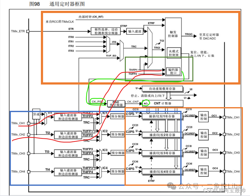
2. Detailed Explanation
As shown in the green box above:
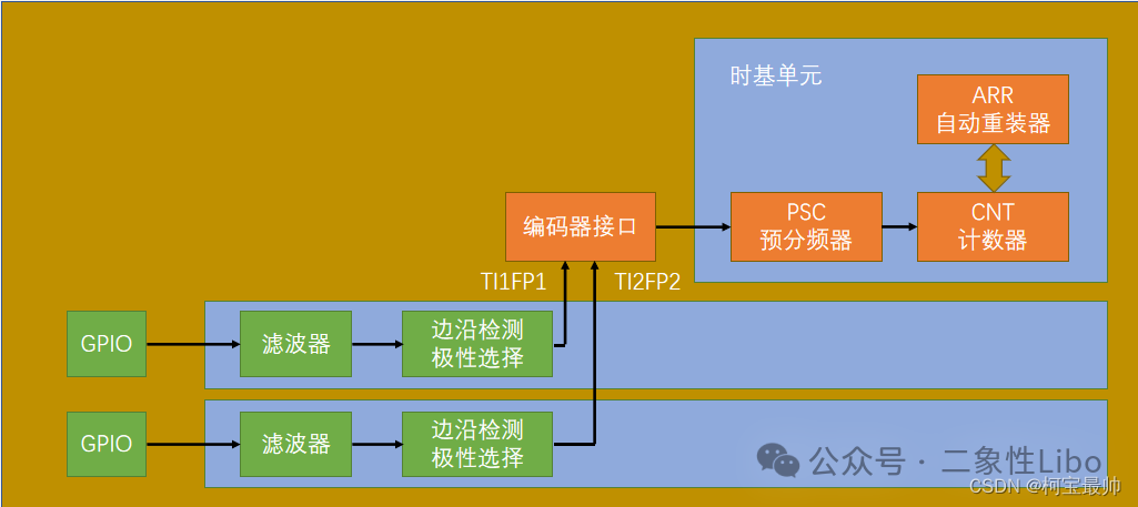
1. The encoder has two input terminals, connected to the A and B phase pins of the quadrature encoder. The two input pins borrow from input capture channels 1 and 2, namely TIFP1 and TI2FP2, which are connected to the input capture channels below.
Thus, the outermost input pins of the encoder are the TIMx_CH1 and CH2 pins at the bottom left of the diagram, with signals from these two pins passing through channel 1 or 2 to TIFP1 and TI2FP2, then to the encoder interface. CH3 and CH4 are unrelated to the encoder interface. (Red line)
2. The output part of the encoder acts as a mode controller, controlling the CNT counting clock and counting direction.
The output execution flow is: when an edge signal appears, and based on the table below, if it is determined to be forward rotation, CNT increments; otherwise, it decrements. Note that the previously used 72MHz internal clock CK_PSC and the counting direction +/- during timer initialization will not be used, as the counting clock and direction are managed by the encoder interface, with CNT incrementing or decrementing controlled by the encoder. (Green line)
Isolating the encoder part:
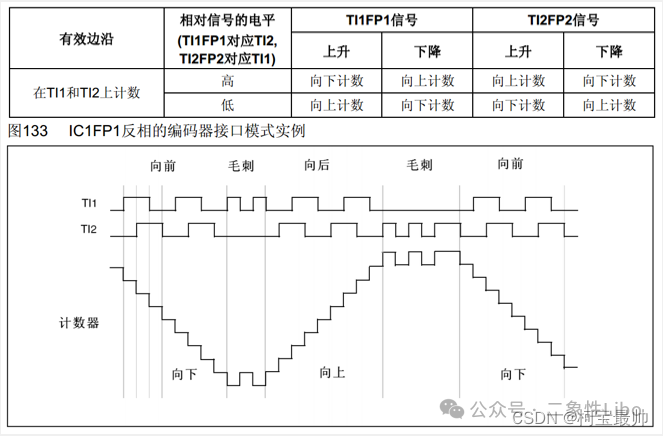
Working Mode: (This table corresponds to the quadrature encoder section below, counting up for forward rotation and down for reverse rotation)
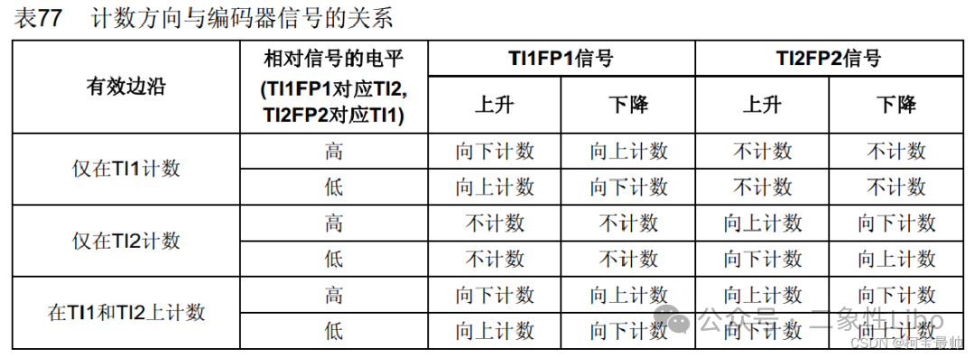
Counting only on TI1 indicates that it only counts the state of phase B when the A phase edge occurs, which is less accurate than counting the state of the other phase at both A and B edges.
Example (no inversion): (The spike part is for noise immunity, and fluctuations are not counted)
Inversion means that two edge detections and polarity selection choose the falling edge parameters, and the signal is inverted through a NOT gate.
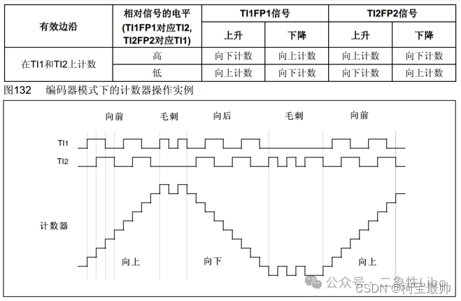
Example (TI1 inverted): (The effect of polarity change on counting)
TI1 inversion means that the digital wave of TI1 below needs to be inverted before corresponding to the table to determine whether to count up or down.
The purpose of the inversion function: for example, if the required forward and reverse rotation (as it is relative to needs) does not correspond to CNT incrementing or decrementing, it can be inverted.
3. Quadrature Encoder
Quadrature: A and B phases are 90° out of phase, and the two phases can indicate direction (forward and reverse are relative):
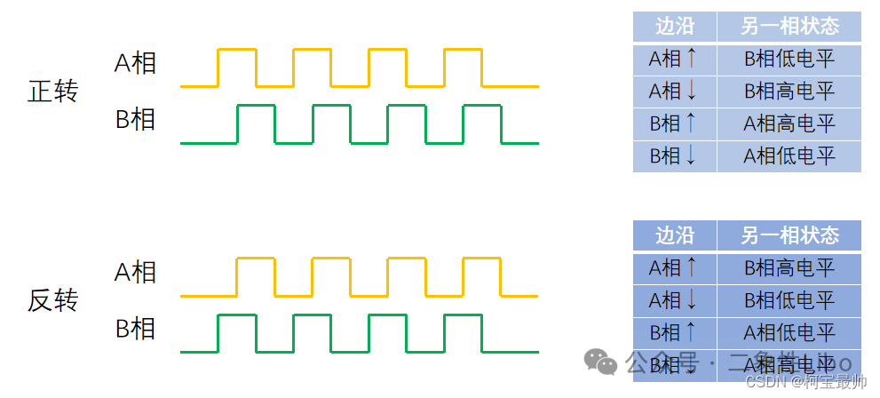
When an edge signal appears, counting increments or decrements, determined by the state of the other phase, allowing for directional counting.
In this restless era, it is commendable that you have read the content to this point!
[Undergraduate Self-Study Notes] To be continued, with over a hundred articles continuously updated…
The next issue will cover practical applications of this section