In vibration testing, vibration sensors serve as the most sensitive devices at the forefront of the testing system, and their stability and accuracy affect the results of the entire test. Therefore, how to select the appropriate sensor becomes very important. This article will introduce some selection tips for vibration accelerometers based on over 30 years of vibration testing experience from Beijing Orient Institute, combined with some indicators from the sensor selection manual, enabling technical engineers to narrow down the options among numerous sensor models and types, ultimately finding the most suitable sensor model to complete the vibration test.
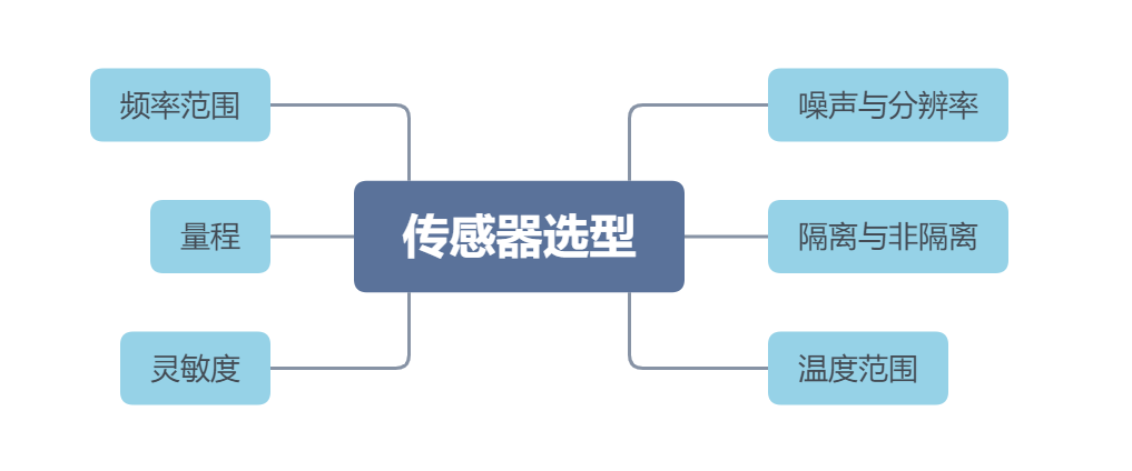
Figure 1.1 Key Technical Parameters for Accelerometer Selection
The frequency of the vibration signal of the measured object generally falls within a certain range, which has a minimum and maximum frequency. Generally, the frequency response curve of the selected sensor should cover the vibration frequency range of the measured object. However, attention should be paid to the error indicated for this frequency response curve, whether it is ±5%, ±10%, or within 3dB; a smaller linear error tolerance indicates higher accuracy.
Piezoceramic (also known as ICP or IEPE type) accelerometers are common types of accelerometers that require an input of 24V and 4~24 mA excitation to operate normally. Due to the built-in IC circuit, achieving very low low-frequency characteristics with this type of sensor is difficult; typically, the lower frequency limit for these sensors is around 0.5Hz, as shown in Figure 1.2 with various sensors’ working frequency ranges and low-frequency limits. If low-frequency components of vibration are particularly important, capacitive zero-frequency accelerometers are a good choice, as their low-frequency limit can be as low as 0Hz, as shown in Figure 1.3.
Note: Here, we select the model of the accelerometer based on the frequency range requirements of the vibration test to narrow down the selection range.
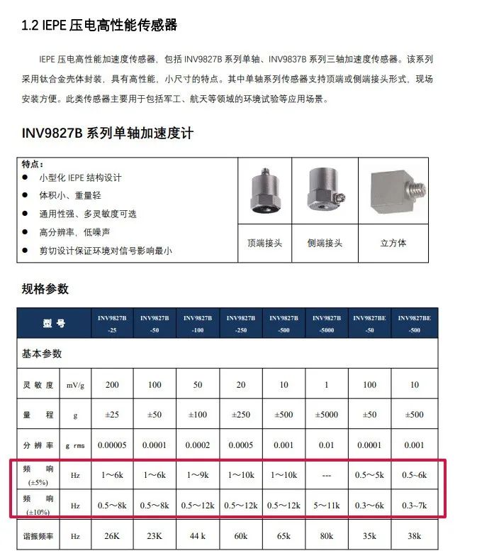
Figure 1.2 Piezoceramic Accelerometer
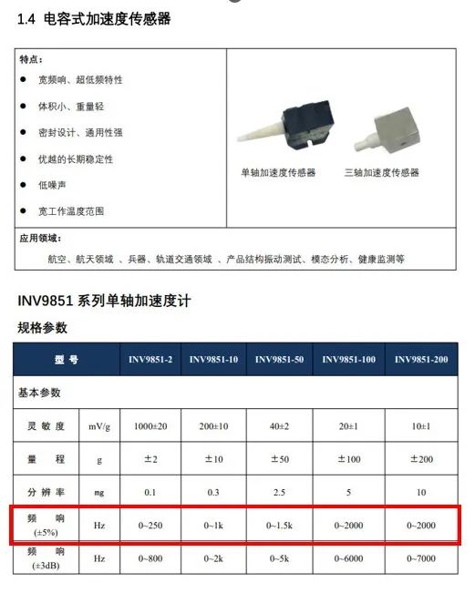
Figure 1.3 Capacitive Zero-Frequency Accelerometer
Another characteristic of the vibration state of the measured object is that the vibration signal has a certain level of vibration magnitude, fluctuating within a certain range, namely the maximum and minimum values of the vibration. The measurement range or range of the vibration accelerometer refers to the maximum and minimum vibration acceleration values that the sensor can measure. The sensor’s range must cover the minimum and maximum values of the test signal, meaning the maximum value measurable by the sensor must exceed the maximum value of the vibration signal, and the minimum value measurable by the sensor must be less than the minimum value of the vibration signal.
If the vibration signal of the measured object exceeds the maximum measurement value of the sensor, it will cause the sensor’s signal output to overload. To prevent sensor overload, the selection is generally based on the maximum value of the vibration magnitude, keeping a certain redundancy, for example, the maximum range of the sensor is more than twice the maximum vibration value.
Analyzing the maximum measurement value of the sensor is to prevent sensor overload, while analyzing the minimum measurement value of the sensor is to obtain effective vibration acceleration signals and prevent the real vibration signal from being drowned out by the sensor’s output noise.
The sensitivity of a vibration accelerometer refers to the ratio between the sensor output signal and the vibration acceleration. When selecting a sensor, after estimating the magnitude of the structure’s vibration, to ensure a good signal-to-noise ratio, the sensor’s sensitivity should be used to calculate the voltage value that the sensor will convert a certain size of vibration acceleration into. Generally, the ratio of the signal voltage value to the background noise voltage value of the testing system should reach at least 10 times to achieve a good signal-to-noise ratio.
For example, when we need to measure the impact of urban rail transit vibrations on buildings according to the JGJ/T170-2009 standard. The standard stipulates that signals need to be measured within the frequency range of 4-200Hz (Figure 1.4) as analysis data, and according to the standard, the minimum vibration limit is 62dB (Figure 1.5). Assuming that this limit differs from environmental vibration by 40dB, the sensor must at least recognize a vibration of 22dB, which converts to an acceleration value of about 0.0000126m/s². Taking the sensor selection manual from Orient Institute as an example, based on the above two conditions, a low-frequency high-sensitivity sensor can be selected, as shown in Figure 1.6. For example, the INV9828-0.1, its frequency range meets the testing requirements, and based on its sensitivity value of 40000mV/g, the minimum limit acceleration from the standard converts to a voltage of 0.05mV. Generally, a 24-bit data acquisition instrument has a background noise of about 0.03mV in its 10V acquisition range. After converting the environmental vibration signal with the INV9828-0.1, the ratio of the collected signal to the background noise of the acquisition system is about 1.7 times, which does not meet the basic signal-to-noise ratio requirement. However, by using the integrated amplifier of the acquisition instrument to amplify the environmental vibration signal voltage by 10 times, it reaches 0.5mV. At this point, the signal-to-noise ratio of the collected signal is approximately 17 times, which has a good signal-to-noise ratio.
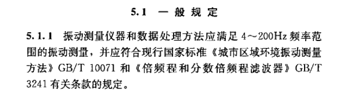
Figure 1.4 JGJ/T170-2009 Standard Vibration Frequency Range Requirements
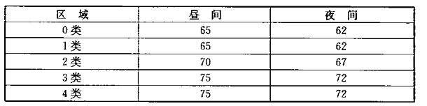
Figure 1.5JGJ/T170-2009 Standard Vibration Limit
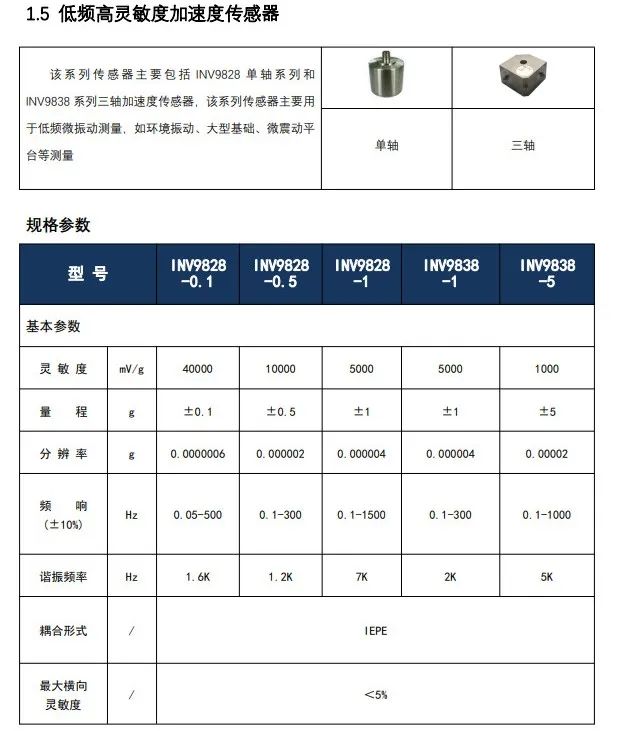
Figure 1.6Low-Frequency High-Sensitivity Accelerometer
4.Noise and Resolution
The noise level of a vibration accelerometer refers to the level of noise signals included in the sensor output signal. Noise often determines the minimum measurable quantity of the sensor, while resolution determines the minimum change that the sensor can measure. After confirming the upper and lower limits of the range, frequency range, and sensitivity, the appropriate sensor can be further selected based on resolution. Figure 1.7 shows the parameters of the commonly used piezoelectric accelerometers from Orient Institute. From the parameters, it can be seen that sensitivity is inversely related to range and resolution; the greater the sensitivity, the smaller the range and resolution.
Note: Under the conditions of meeting the range, frequency response range, and appropriate signal-to-noise ratio, a sensor with a smaller resolution can be selected to improve testing accuracy.
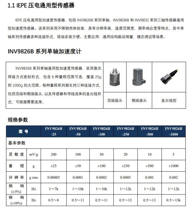
Figure 1.7 IEPE Piezoelectric General Accelerometer
5.Isolated vs. Non-Isolated
If there is strong electromagnetic interference in the testing environment or the measured object’s shell is electrified, we can consider choosing an isolated accelerometer. Some may question whether using a conventional non-isolated sensor with anti-interference or insulation treatment during installation would also work? Of course, that is possible. However, for short-term detection, it is necessary to consider the workload of on-site installation and deployment. Clearly, using an isolated sensor can shorten the preparation time for the test and improve test efficiency. In long-term monitoring scenarios, long-term operational stability needs to be a key consideration, making the use of isolated sensors a better choice. Figure 1.8 shows the industrial monitoring-type isolated accelerometer.
So, what is electrical isolation? The electrical isolation capability of a sensor is generally indicated in the sensor’s parameter specifications, usually classified as non-isolated, bottom-isolated, and shell-isolated. Non-isolated means that the sensor’s shell and signal ground are connected. If such a sensor is installed directly on the measured structure, and if the surface of the measured structure has strong electricity, signals will be introduced into the acquisition system. If this voltage is far higher than the maximum voltage that the testing system can withstand, it will damage the testing system. Bottom-isolated means that the bottom of the sensor is not connected to the signal ground, but the sensor shell is connected to the signal ground. Shell-isolated means that the sensor shell is completely isolated from the signal ground. Isolated sensors and non-isolated sensors can generally be easily distinguished visually. In Figure 1.9, the left side is a non-isolated sensor, and the right side is an isolated sensor; their interface differences are very obvious. The non-isolated sensor has only one core as the signal positive, while the isolated sensor has two cores, one for signal and one for ground. Industrial sensors for monitoring are generally isolated.
Note: For long-term mechanical structure vibration monitoring in harsh electromagnetic environments, it is recommended to use this model of sensor.
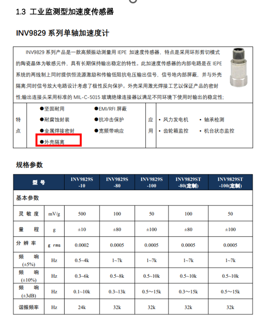
Figure 1.8 Industrial Monitoring Accelerometer
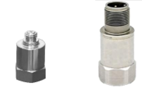
Figure 1.9 Non-Isolated vs. Isolated Sensors
6.Temperature Range
If the sensor’s working environment exceeds 90℃, attention should be paid to selecting the working temperature range of the sensor. Generally, the temperature limit for conventional IEPE accelerometers is around 120℃ due to the integrated circuit inside, while specially designed ones can reach up to 175℃. For environments with even higher temperatures, charge-type piezoelectric sensors can be chosen. Figure 1.10 shows the high-temperature sensor series INV9815 from Orient Institute.
Note: For test runs of aircraft engines on test benches or other high-temperature vibration tests, in addition to meeting the above conventional parameter conditions, high-temperature charge-type accelerometers are often selected.
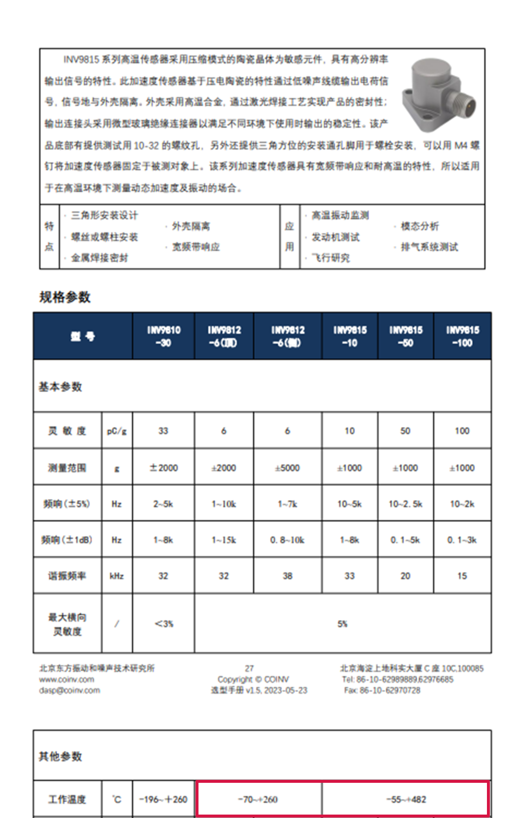
Figure 1.10High-Temperature Charge-Type Accelerometer
About Beijing Orient Institute
In its early days, the Orient Institute proposed the concept of virtual instruments, and for nearly forty years, it has focused on the development of software and hardware in the fields of vibration, impact, noise, strain, dynamic testing, signal processing, modal analysis, virtual instruments, and measurement and control technology, ultimately achieving the vision of “taking the laboratory with you.” The DASP series software and INV series hardware independently developed by the Orient Institute have been widely used in various industries such as aerospace and military, rail transit, mechanical equipment, large structures, energy and environment, and metrology.