Introduction
In this section, we will discuss the WiFi chip ESP8266 used in the STM32 FOTA example. This involves the ESP-01 WiFi module based on the ESP8266 chip, developed by Ai-Thinker. In the STM32 FOTA Demo project, we use it to achieve wireless communication. First, let’s get to know this module, and then we will focus on the implementation process of the underlying drivers related to the ESP8266 chip in the Demo.
ESP-01 Module
The ESP-01 module integrates the ESP8266EX WiFi chip, supports the 802.11b/g/n protocol, and interfaces with UART/GPIO, embedding the LwIP protocol stack. It supports STA/AP/STA+AP working modes, making it a low-cost wireless module.
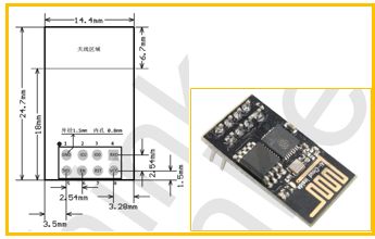
The ESP-01 module uses a DIP-8 package. The dimensions and pin definitions are shown in the figure below. It provides one UART interface and two GPIO pins.
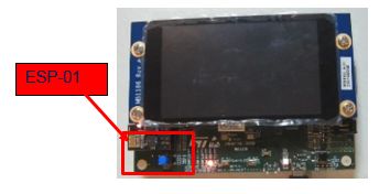
The CN2 interface of the STM32F769 discovery board supports the expansion of the ESP-01 module, allowing the ESP-01 module to be directly plugged into the CN2 interface. Communication between the STM32F769 and the ESP-01 is done via UART, configured as follows: 115200 baud rate, 8 data bits, no parity, and 1 stop bit. The connection is as follows:
AT Command Format
The AT command set for the ESP-01 is the same as that of the ESP8266. It can be subdivided into four types:
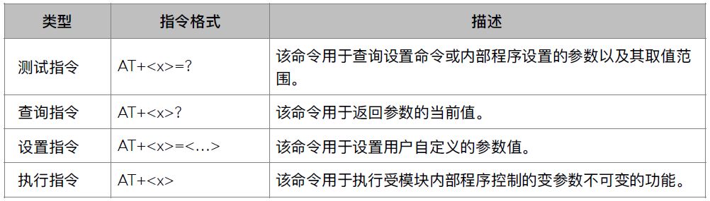
It is important to note that not every AT command falls into the above four categories; specific details can be found in the documentation for each AT command.
String data is represented using double quotes. For example, “123” is a string, while 123 is a number.
The first two characters of the AT command must be uppercase, and each command ends with a carriage return and newline character “\r\n”.
The AT command set for the ESP8266 is further divided into: Basic AT commands (for module configuration, UART settings, etc.), WiFi function AT commands (for setting WiFi modes, connecting to APs, etc.), and TCP/IP function AT commands (for establishing TCP connections, sending and receiving data, etc.).
Working as a TCP Client
Module Initialization
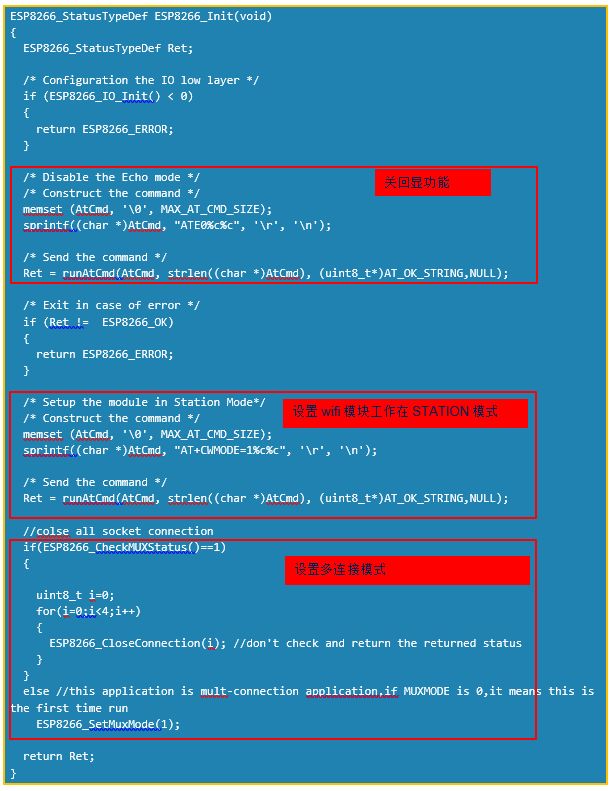
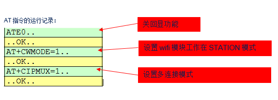
After powering on the program, the WiFi module must be initialized before use. In addition to initializing GPIO and UART, the WiFi module needs to be configured to operate in the desired mode. In the STM32 FOTA Demo, the ESP8266 should operate in STATION mode and multi-connection mode. Therefore, during initialization, it must be configured using the appropriate AT commands. Below is the initialization code and the process of executing the AT commands.
Connecting to AP
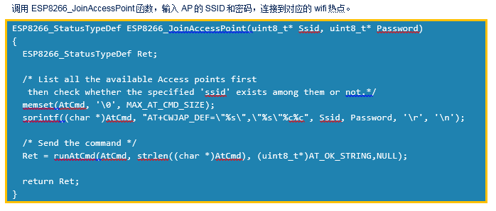
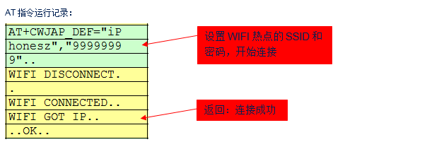
The yellow part of the above image shows the return status of the WiFi module. It is essential to receive “OK\r\n” before reading the IP address. The time required to connect to the WiFi hotspot can vary; sometimes it takes 2-3 seconds, and other times 6-7 seconds. Therefore, it is advisable to allow a longer wait time to avoid frequent connection failures.
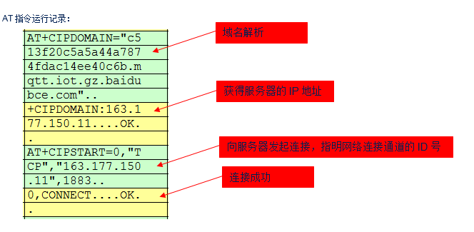
Establishing Connection with the Server
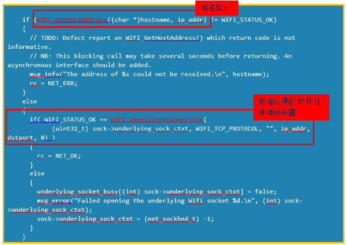
After connecting to the WiFi hotspot, you can start establishing a connection with the server. The ESP8266 supports up to 5 concurrent connections.
Typically, we do not know the target server’s IP address but rather its domain name. Therefore, before creating a connection, we need to obtain the corresponding IP address through DNS services. The ESP8266 also provides the relevant AT commands.
Below is a segment of code related to establishing a connection:
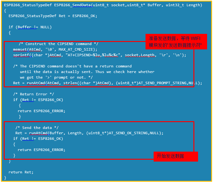
Sending Data
The data sending process consists of two steps:
1. Send the command AT+CIPSEND=<LINK ID>,<LENGTH> to specify which socket channel to send a certain number of bytes of data.
2. After receiving “OK\r\n>” from the WiFi module, send the data.
Below is the code implementation for sending data with the ESP8266 in the example.
Receiving Data Mode
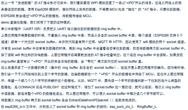
Note: In this example, both MQTT and HTTP applications are called within the same task. If implemented in different tasks, the receiving driver needs to be modified accordingly.
Summary
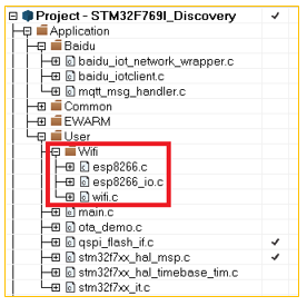
In the example, the drivers related to the WiFi module consist of three layers:
The ESP8266_io.c file contains the lowest layer that interacts with the STM32 peripherals, including pin initialization and reading/writing data from/to the UART;
The Esp8266.c file implements the AT commands.
The Wifi.c file serves as an interface between the WiFi low-level driver and the upper layer. We can see that its function names are quite similar to some functions in ESP8266.c.
The content we discussed earlier is primarily contained within these three files. If you want to replace the WiFi module, the code mainly involves these three parts.
↓↓↓ Click “Read More” to learn more details.