This note can be skipped by experienced users. Everything before entering is an obstacle, but looking back after entering, everything seems simple.
Introduction to GPIO
GPIO stands for General Purpose Input/Output. All pins of the STM32, except for specific functions like power and ground, VBAT, etc., can be used as GPIO. STM32 categorizes them into five groups (A-E), each containing 16 pins, which are used to read or output levels. It is important to note that these levels are 3.3V CMOS levels, and almost all ports can tolerate 5V signals, but it is advisable to refer to the datasheet for specific tolerances.
GPIO Function Description
GPIO ports are managed by groups (registers are organized by groups), with a set of registers precisely controlling various working states of each internal circuit. The block diagram of each bit is as follows (the VDD connected to the protection diode of the pins that can tolerate 5V is VDD_FT, the others are the same):
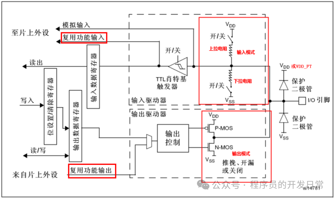
Under the register settings, there are a total of eight modes, which can be reclassified into four input modes, two output modes, and two multiplexing modes, summarized as follows:
|
Mode |
Description |
Characteristics |
|
Input Floating |
The signal is sent from the TTL Schmitt trigger to the input data register, with both pull-up and pull-down switches disconnected. If you need to detect whether an external connection is high or low, such as button detection, you need to specify this mode. |
No pull-up or pull-down, no default input level |
|
Input Pull-Up |
Only the pull-up switch is connected, defaulting to high level, able to detect if the level has dropped. |
Default high level |
|
Input Pull-Down |
Only the pull-down switch is connected, exactly the opposite of pull-up. |
Default low level |
|
Analog Input |
1. Output is disabled, Schmitt trigger output (output control) value is forced to ‘0’; 2. Schmitt trigger input is disabled, signal is read directly without going through the Schmitt trigger; 3. Weak pull-up and pull-down resistors are disabled; 4. When reading the input data register, the value is ‘0’. |
Dedicated for AD sampling, zero consumption on each analog I/O pin |
|
Push-Pull Output |
Both PMOS and NMOS switches are turned on, this mode has the strongest drive capability. |
Strongest driving capability |
|
Open-Drain Output |
PMOS is turned off, NMOS is turned on, the drain is externally connected, which is the high-impedance state in digital circuits. |
No ability to output high level, but can output low level |
|
Push-Pull Multiplexing |
The multiplexing function allows GPIO to become designated pins for a specific peripheral module: 1. In open-drain or push-pull configuration, the output buffer is enabled; 2. Built-in peripheral signal drive output buffer (multiplexing function output); 3. Schmitt trigger input is activated; 4. Weak pull-up and pull-down resistors are disabled; 5. Data appearing on the I/O pin is sampled to the input data register during each APB2 clock cycle; 6. In open-drain mode, reading the input data register can obtain the I/O port status; 7. In push-pull mode, reading the output data register can obtain the last written value. Both push-pull and open-drain multiplexing refer to output, and there are also inputs during multiplexing. |
It is no longer used as GPIO, but becomes the input/output pin of a specific module, such as TX and RX of a serial port. |
|
Open-Drain Multiplexing |
In addition to being configurable to these eight modes, it also has the following functions:
1. Each bit can be set individually; 2. In input mode, each bit can trigger external interrupts; 3. Software remapping of I/O multiplexing function. To optimize the number of peripheral I/O functions for different device packages, some multiplexing functions can be remapped from the original pins to other pins. This can be done by configuring the corresponding registers through software (refer to AFIO register description); 4. GPIO locking. Allows freezing of IO configuration. Once a lock (LOCK) program is executed on a port bit, the configuration of that port bit cannot be changed until the next reset.
HAL Library API
The STM32 HAL library provides a set of API functions for each module to access the corresponding peripheral registers. These APIs encapsulate the details of low-level hardware operations, providing a unified operating interface. Therefore, understanding what operations are available in each module’s API is essential. Knowing which registers are involved can give a rough idea of which registers are being operated on after seeing the API. If proficient with pointers, one can also directly manipulate registers in the code for so-called high efficiency.
There are two files for GPIO operations in the HAL library, namely basic operations stm32f1xx_hal_gpio.c and extended operations stm32f1xx_hal_gpio_ex.c. These operation APIs can be divided into setting functions, operation functions, and callback functions.
Setting Functions
There are two setting functions, initializing a port and de-initializing a specific pin (restoring to the default state after power-up):
 These two functions operate on the high and low eight-bit registers GPIOx_CRH, GPIOx_CRL, and the GPIO_TypeDef type describes which port it is. These ports are defined in
 stm32f107xc.h (different series will have different definitions, all peripherals are defined in this file).:

Here, the mapping of the specific structure to the hardware entity address is completed, and each structure contains all the registers of GPIO:
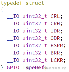
Note not to modify the order of the registers in this structure, as the structure’s linear addresses correspond to the addresses in the peripheral. GPIO_InitTypeDef corresponds to the high and low bit registers of the port:
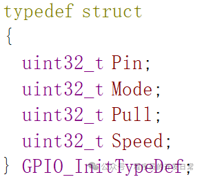
In summary, this structure describes which pin, what mode, whether to pull up or down, and the speed. The pin definitions are in stm32f1xx_hal_gpio.h:
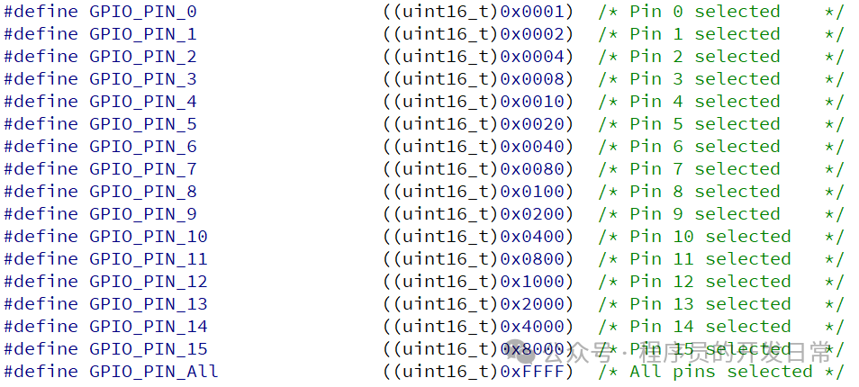
It can be seen that there is a somewhat troublesome issue, as the definitions of these parameter types are scattered across different header files, requiring users to have a certain memory. The IDE tool can automatically complete the input after defining the name in the input section for quick input, but cannot directly link to view which parameters are available through the function type, such as in the function definition below:
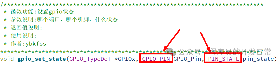
In qtcreator, holding down ctrl and clicking on the defined name GPIO_PIN can jump to the specific selectable parameters:
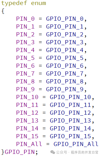
However, if the parameter type is just a uint32_t, you know it is a number, but you cannot determine the range of these numbers. By packaging these scattered values through enumeration, the specific data will be very clear. Unfortunately, there are a lot of such scattered definitions in the HAL library.
Operation Functions
GPIO_PinState HAL_GPIO_ReadPin(GPIO_TypeDef *GPIOx, uint16_t GPIO_Pin); // Read the input level of the pin
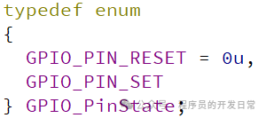
void HAL_GPIO_WritePin(GPIO_TypeDef *GPIOx, uint16_t GPIO_Pin, GPIO_PinState PinState); // Specify the output level of the specified pin, GPIO_PinState defines the high and low levels of the pin output:
void HAL_GPIO_TogglePin(GPIO_TypeDef *GPIOx, uint16_t GPIO_Pin); // Specify the pin level to toggle
HAL_StatusTypeDef HAL_GPIO_LockPin(GPIO_TypeDef *GPIOx, uint16_t GPIO_Pin); // Lock the configuration of the pin, note that it does not lock the input or output state of the pin
Callback Functions
void HAL_GPIO_EXTI_IRQHandler(uint16_t GPIO_Pin); // External interrupt handler for the pin. This function is called by the interrupt service function located in stm32f1xx_it.c, such as:
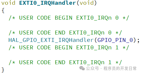
All external interrupts for the pins share a single handler function.
void HAL_GPIO_EXTI_Callback(uint16_t GPIO_Pin); // External interrupt handling callback function for the pin. This function is called by HAL_GPIO_EXTI_IRQHandler. The content to be processed during the interrupt is directly operated in this callback function, without needing to separately clear the interrupt flag, as the HAL library has already handled it at the lower level:
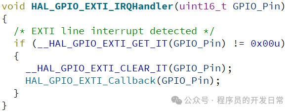
This is different from the standard library. It is important to note that the name of the interrupt callback function is predefined in HAL and cannot be misspelled. Additionally, the callback function does not need to be declared again in the header file; it can be defined anywhere (not recommended to place it randomly).
If you are curious why the compiler does not report an error when defining two identical functions in C, you can jump to the .c file to see:
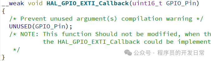
The key to achieving this is to add a __weak before it, which is a weak definition. Functions with this label have a characteristic: if you do not define it, the default will be used; if a new definition exists, the new defined function will be called to complete the operation. This is similar to virtual functions in C++, where if a subclass has a definition, it calls the subclass; if not, it uses the parent class to operate.
Macro Operations
Each module in the HAL library has a large number of macro operations, which encapsulate direct operations on registers. At first glance, their definitions seem no different from functions, such as the __HAL_GPIO_EXTI_GET_FLAG macro:

The English description specifies the parameters and return value types, but ST has not wrapped them into functions. You may wonder why; the reason is that wrapping them into functions would require an additional stack layer during the call, and in some microcontrollers, the number of stack layers is limited. Therefore, for such simple operations, the HAL library uniformly defines them as macros.
|
Macro Operations |
Description |
|
__HAL_GPIO_EXTI_GET_FLAG(__EXTI_LINE__) __HAL_GPIO_EXTI_GET_IT(__EXTI_LINE__) |
Get the specified external interrupt line flag; these two operations correspond to the same operation:
|
|
__HAL_GPIO_EXTI_CLEAR_FLAG(__EXTI_LINE__) __HAL_GPIO_EXTI_CLEAR_IT(__EXTI_LINE__) |
Clear the EXTI pending flag; these two operations correspond to the same operation:
|
|
__HAL_GPIO_EXTI_GENERATE_SWIT(__EXTI_LINE__) |
Generate a software interrupt on the selected EXTI line |


The registers operated by these macros belong to external interrupts. Some macro operation names differ, but the corresponding register operations are exactly the same, probably for compatibility with historical versions. The parameter __EXTI_LINE__ can take values from GPIO_PIN_0 to GPIO_PIN_15.
Extended Functions
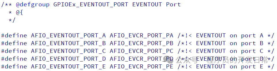
void HAL_GPIOEx_ConfigEventout(uint32_t GPIO_PortSource, uint32_t GPIO_PinSource); // Configure GPIO pins for event output, the parameter output range of GPIO_PortSource is defined in stm32f1xx_hal_gpio_ex.h as follows:
The parameter range of GPIO_PinSource is:
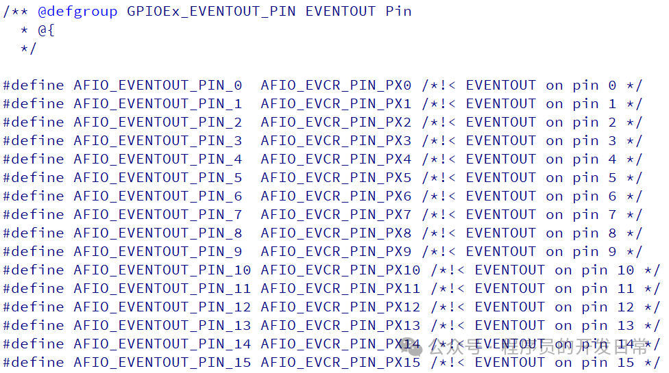
void HAL_GPIOEx_EnableEventout(void); // Enable the event output function of the GPIO pin
void HAL_GPIOEx_DisableEventout(void); // Disable the event output function of the GPIO pin
Extended Macro Operations
In the stm32f1xx_hal_gpio_ex.h file, there are also a large number of macro operations, including two judgment macros:
IS_AFIO_EVENTOUT_PIN(__PIN__)
IS_AFIO_EVENTOUT_PORT(__PORT__)
More are similar to __HAL_AFIO_REMAP_SPI1_ENABLE() remapping switches, which are self-explanatory and will not be listed one by one here.
Experiment
Create a project named 107_gpio_test, which aims to output a 1Hz square wave on PB0, with PB0 connected to the board’s LED via a Dupont wire. The driving circuit is as shown:
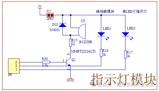
This circuit is very simple, with a 5V power supply connected to the LED through a 1K resistor directly to the pin. Note the value of this resistor; different colored LEDs have different forward voltage drops, and if you want similar brightness, the resistance values will also need to be different. Be careful not to connect one resistor to two different colored LEDs.
CUBEMX Settings
If you are still stuck in the era of manually configuring registers, this microcontroller does have a certain threshold. You need to configure the clock tree first, and then to use a certain module, you also need to enable the corresponding clock. You definitely do not want to flip through the manual to repeat these necessary operations. CUBEMX solves this problem; once you use it to configure the corresponding module, you no longer need to focus on these basic operations and can concentrate on code logic development.
Create a project, first open CUBEMX, click file, and create a new project, selecting the target chip 107VC. Following the previous operations, select SW debugging in SYS, set the clock to external crystal, and focus on setting PB0:
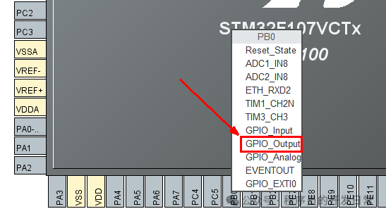
Pin configuration is handled by default:
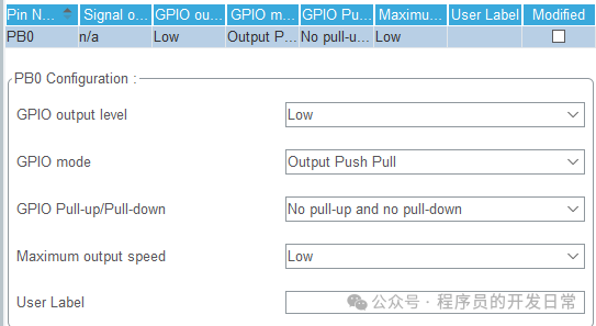
GPIO output level: the high and low levels of the output correspond to the operation register BSRR.
GPIO mode: two output modes, push-pull and open-drain, correspond to the operation registers CRH and CRL.
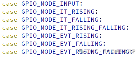
GPIO Pull-up/Pull-down: the pull-up and pull-down modes during input, this item is meaningless for output mode configuration. The following situations accept pull-up and pull-down:
Maximum output speed: three speed selections in output mode correspond to the operation registers CRH and CRL.
The “User Label” above indicates the user label, which is the macro definition of this pin. If it is for actual project development, this method can enhance the readability of the code.
Selecting “GPIO_Output” and “GPIO_Input” will show different interfaces above, but both configure the port configuration registers CRH and CRL. Keep the clock configuration default, set the project name and storage location in the project settings, and click to generate code:
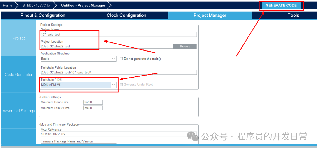
After generating the code, directly open the folder, in the MDK-ARM directory, start MdkTool, drag 107_gpio_test.uvprojx into the interface, and you will see that a pro file has been added in this directory:
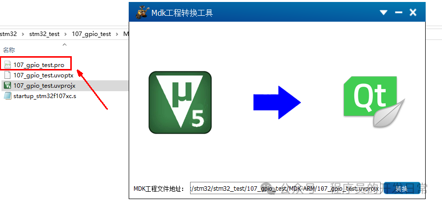
The “Convert” button does not need to be clicked; dragging it in means you want to generate it. This button is reserved for the purpose that if you delete the pro file, clicking this button can regenerate it without restarting this tool. Double-click the generated pro file, and the system will call qtcreator to open it:
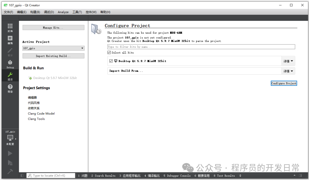 You may have installed another version of QT:
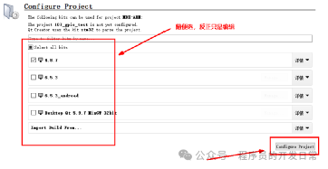
Select any one, as long as “Configure Project” can be clicked, click to open the project, expand the left file list, and double-click main.c:
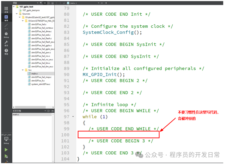
There are many comments here, with BEGIN and END appearing in pairs. Be careful not to delete them; our own code should be added between BEGIN and END, otherwise, if you modify the configuration (calling CUBEMX to open the .ioc file), the code you added will be overwritten. Remember, there is no regret medicine.
Experimental Phenomenon
At this point, the entire running framework has been completed. CUBEMX has configured the clock and initialized PB0 (the specific code is in the MX_GPIO_Init function), and you still need to add the running logic yourself:
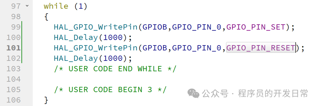
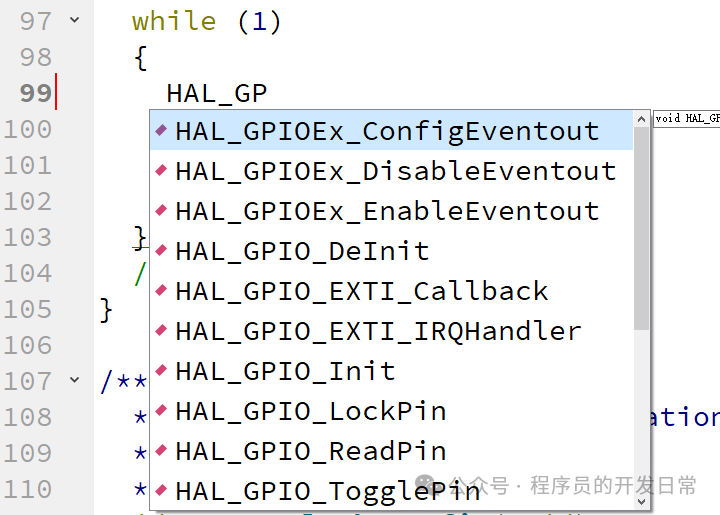
These functions are very characteristic, all starting with HAL_. When you type HAL_, qtcreator has already started suggesting which types are available for selection, and you can choose using the up and down keys:
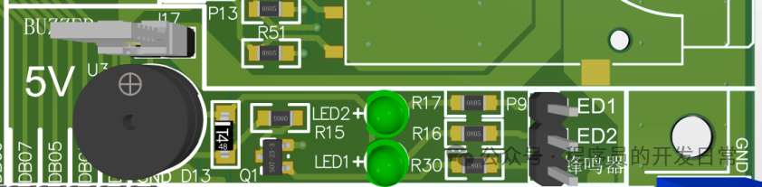
Connect the J17 jumper cap, and LED1 is directly connected to PB0:
Open the corresponding Keil project, compile and download, then press the RST button on the board to reset and observe the phenomenon:
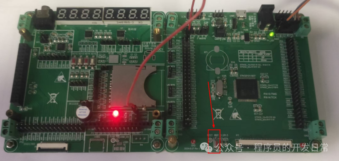
It shines, perfect. Conveniently, if you plug the Dupont wire directly into the buzzer interface, you will find that the buzzer also sounds once and then stops. In fact, this circuit is the most common sound and light alarm circuit. Driving it in software is very simple; just provide high and low levels. However, when selecting hardware, the following considerations need to be taken into account:
1. When selecting LEDs, the color should conform to human habits. The commonly used colors are red, green, and yellow, similar to traffic lights. Everything is normal, the green light is on; if overloaded, limited current, or system alarm, the yellow light is on. For example, in some power modules, a serious problem will light up the red light. Alternatively, the red light indicates charging, and the green light indicates fully charged. Additionally, different colored lights have different prices, so try not to choose rare colors.
2. The LED body selection should not be transparent. Although it is cheaper, its light does not spread out, and it can be glaring when viewed directly. The display effect is also poor; frosted ones are recommended.
3. Different colored LEDs have different forward voltage drops, so the values of pull-up or pull-down resistors will also differ. Do not use one resistor to pull two different colored LEDs.
4. The buzzer I have here has a built-in oscillation circuit. Its advantage is simple to drive, but the disadvantage is a single sound frequency. However, it meets most usage scenarios. If you need to produce different frequency sounds, you need to choose one without an oscillation circuit, and the software driving method needs to be changed to PWM waves.
5. Whether the diode behind the buzzer can be omitted depends on the situation. If it has a built-in driver, it can theoretically be omitted. If it does not have a driver, it is best not to omit it, as the back EMF generated by the buzzer’s dynamic coil will directly hit the collector of the transistor. Although the current and frequency of the buzzer will not be too large, use an oscilloscope to check the actual maximum value of the back EMF. If the withstand voltage value differs by 2 times, you can confidently omit it.
Code Interpretation
We have seen the experimental phenomenon; it has become something you can obtain. Now let’s look back at the entire code implementation:
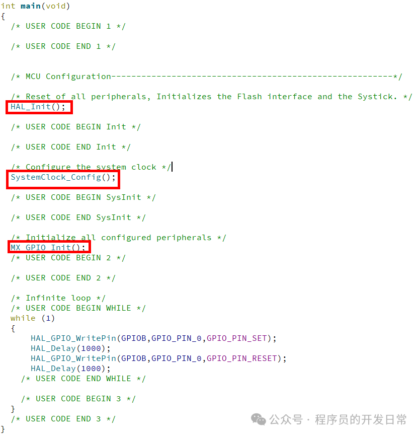
HAL_Init
The three functions in the above boxes are generated by CUBEMX, and they are buried in this pile of comments. First, let’s look at the first function HAL_Init. This function is the first one to be called when using the HAL library, and it performs the following operations:
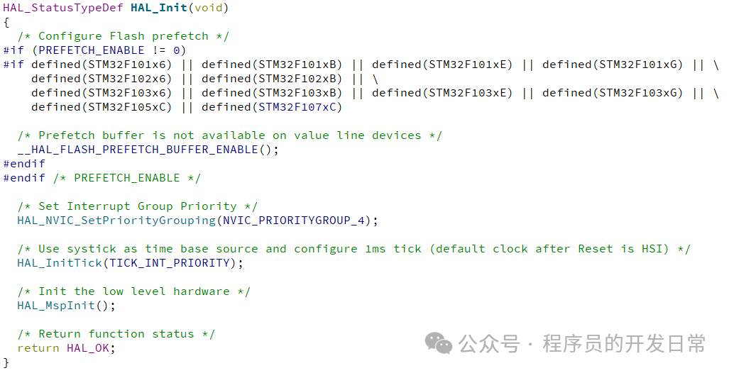
This function has four steps of operation, giving a rough idea to have a basic understanding:
1. __HAL_FLASH_PREFETCH_BUFFER_ENABLE();
This enables the FLASH prefetch buffer function, meaning that when this instruction is executed, the next instruction to be executed is fetched in advance. The corresponding register is the FLASH access control register (FLASH_ACR) with the PRFTBE bit:
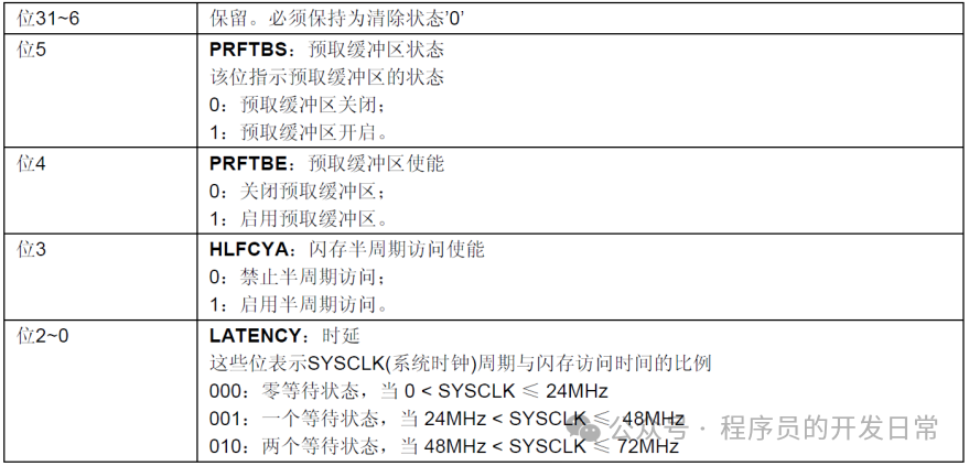

This register is described in the “STM32F10xxx Flash Programming” document. Do not get tangled or confused; some questions must be set aside when you first start. The focus of GPIO is definitely GPIO.
2. HAL_NVIC_SetPriorityGrouping(NVIC_PRIORITYGROUP_4);
The interrupt grouping is set to group 4, where all interrupts only have preemption priority, without response priority. The lower the preemption number, the higher the priority. The subsequent interrupt content will involve this.
3. HAL_InitTick(TICK_INT_PRIORITY);
Millisecond timer initialization; HAL_Delay counts on this timer, which by default uses the systick in the M3 core, but can also be changed to any of TIM1 to TIM7 in CUBEMX:
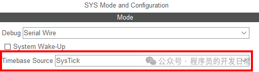
The default parameter for this function is the priority of the timer, with the macro definition of 0 indicating the highest priority:

Although the comment here states that it is lowest by default, in fact, the lower the number, the higher the priority.
4. HAL_MspInit();
Low-level hardware initialization. This function is a weak definition, and the actual execution body is in stm32f1xx_hal_msp.c. The specific operations are as follows:
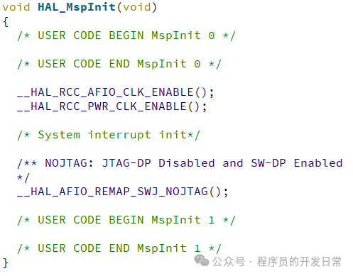
The operations in this code can be inferred from the function names, which is a very good self-commenting style. CUBEMX considers that you may also need to add your own code in this function and has reserved space at the beginning and end of this function.
SystemClock_Config
System clock tree configuration, which sets the frequency dividers, multipliers, and clock paths shown in the figure below:
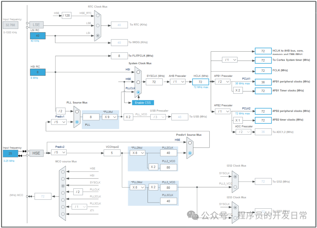
When there is an error in clock processing, the Error_Handler function will be called. This function is located in main.c:

By default, it is empty, and CUBEMX leaves the error handling to the user.
MX_GPIO_Init
This function is the focus of GPIO, performing three actions: enabling the clock, setting the output state, and configuring the port pin state:
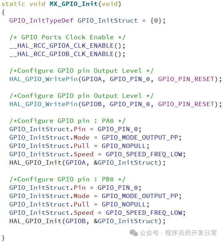
Note that here, the output state is set first, and then the port state is configured. Our general habit is to configure first and then assign values. In this case, it does not actually affect the operation because they correspond to different registers. Observe the assignments of GPIO_InitStruct for PA0 and PB0; the values in the structure are identical, but all four member variables are assigned twice. This is a limitation of the tool, as the tool generates code based on your two different settings.
Through this function, the usage steps can be summarized as follows:
1. Enable the clock for the corresponding GPIO port: __HAL_RCC_GPIOA_CLK_ENABLE();
2. Set the GPIO state: HAL_GPIO_Init(GPIOA, &GPIO_InitStruct);
3. Set the output level value: HAL_GPIO_WritePin(GPIOA, GPIO_PIN_0, GPIO_PIN_SET);
Logic Code
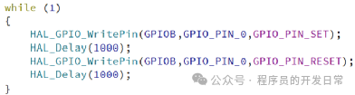
For bare-metal development without an operating system, all repetitive operations are placed in this infinite loop. Here, it simply sets an output and calls a delay to maintain the port level state for a period of time. The main logic is quite simple.
Precautions
In hardware design, the first thing to pay attention to is the 5V voltage tolerance issue, which means that directly connecting 5V voltage to pins is limited to certain specific pins. You need to refer to the PDF manual for specifics:
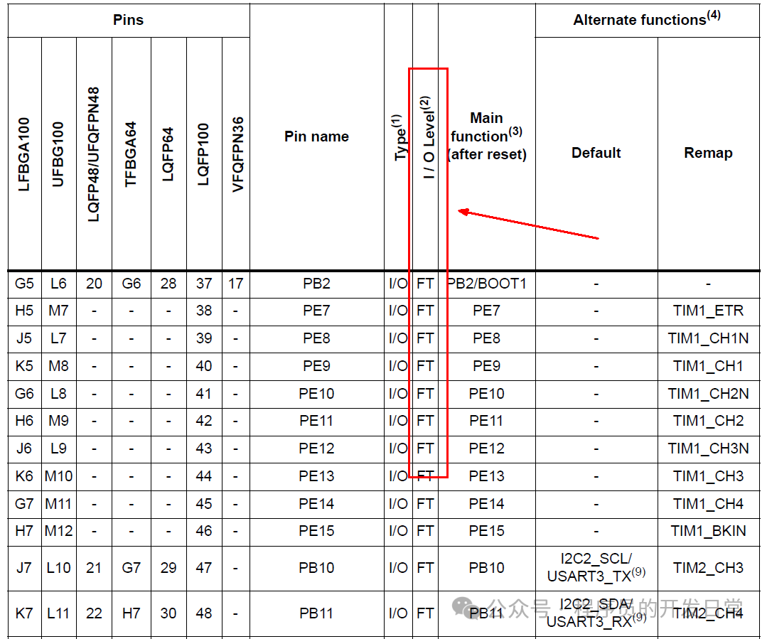
All I/O levels that are FT can be directly connected to 5V without issue. The second point to note is that while these pins can light up LEDs without issue, if you want to drive high-power devices, you need to add dedicated driver circuits. Additionally, do not assume that every pin has a protection diode and is safe; it can still be broken down. If in doubt, use a multimeter to measure; if it conducts in reverse to ground, it is damaged, although your microcontroller may still run.