Over 70,000 friends have followed the industrial control WeChat platform:Technical sharing,Learning exchange,Industrial control videos
Solutions to RS485 Communication Port Damage in Siemens S7-200 PLC:
1. Internal RS485 Interface Circuit Diagram of S7-200 PLC:
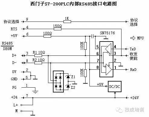
In the diagram, R1 and R2 are ordinary resistors with a resistance of 10 ohms, which serve to prevent excessive current from damaging the chip when the RS485 signals D+ and D- are short-circuited. Z1 and Z2 are Zener diodes with a clamping voltage of 6V and a maximum current of 10A. The 24V and 5V power supplies share a common ground without isolation. When there is common mode interference voltage on the D+ or D- line, the bridge rectifier circuit and Z1, Z2 can clamp the common mode voltage to ±6.7V, thus protecting the RS485 chip SN75176 (the allowable common mode input voltage range for the RS485 chip is -7V to +12V). This protection circuit can withstand common mode interference voltage power of 60W, and there are no anti-static measures within the protection circuit and chip.
2. Analysis of Common Failure Phenomena:
When the RS485 port of the PLC is connected to a computer via a non-isolated PC/PPI cable, or when connecting PLC to PLC or PLC to frequency converters, touch screens, etc., there are often instances of communication port damage. Common damage situations include:
● R1 or R2 burned out, while Z1, Z2, and SN75176 are intact. This is due to a large transient interference current passing through R1 or R2, the bridge rectifier, and Z1 or Z2 to ground. Z1 and Z2 can withstand a maximum current impact of 10A, while the transient power generated on R1 or R2 is: 102×10=1000W, which will certainly burn them out.
● SN75176 damaged, while R1, R2, and Z1, Z2 are intact. This is mainly due to static discharge or transient overvoltage occurring faster than the action speed of Z1 and Z2, as static electricity is ubiquitous, and even the human body can generate ±15kV of static electricity.
● Z1 or Z2, SN75176 damaged, while R1 and R2 are intact. This may be due to high voltage low current transient interference voltage breaking down Z1 or Z2 and SN75176. Since the current is small and the occurrence time is short, R1 and R2 do not heat up and burn out.
From the above analysis, it can be concluded that the main reasons for PLC interface damage are transient overvoltage and static electricity. The causes of transient overvoltage and static electricity are numerous and complex, such as the common grounding of the internal 24V and 5V power supplies of the PLC, where the output terminals L+ and M of the 24V power supply may cause ground potential changes when mixed powering other devices, resulting in common mode voltage exceeding the allowable range. Therefore, the EIA-485 standard requires that the signal grounds of each RS485 interface be connected together with a low-resistance wire to ensure equal ground potential at each node and eliminate ground loop currents!
When hot-plugging non-isolated connecting cables, due to unequal potentials at both ends and the presence of various inductive and capacitive components in the circuit, transient overvoltage or overcurrent is inevitably generated at the moment of plugging or unplugging.
Transient overvoltage or overcurrent generated by other devices connected to the RS485 bus will also flow into the PLC. The more devices connected on the bus, the more factors there are that can cause transient overvoltage.
When the communication line is long or has overhead lines, lightning will inevitably cause overvoltage on the line, often resulting in significant energy, and users often express frustration saying, “All the PLCs connected to the network were damaged!”.
3. Solutions:
1. Consideration from within the PLC:
● Use isolated DC/DC converters to isolate the 24V and 5V power supplies. This is also the case for Mitsubishi, Omron, Schneider PLCs, as well as Siemens’ PROFIBUS interface.
● Choose high-grade RS485 chips with perfect protection measures such as static protection, overheat protection, and input failure protection, such as SN65HVD1176D, MAX3468ESA, etc. These chips generally cost tens of yuan, while the price of SN75176 is only 1.5 yuan.
● Use new protective devices like TVS or BL surge absorbers that respond faster and can withstand higher transient power. For example, the clamping voltage of P6KE6.8CA is 6.8V, and it can withstand transient power of 500W, while BL devices can withstand surge currents of over 4000A.
● Use positive temperature coefficient self-resetting fuses (PTC) for R1 and R2, such as JK60-010, which has a normal resistance value of 5 ohms and does not affect normal communication. When subjected to surge impacts, a large current flows through the PTC and protective device TVS (or BL), causing the resistance value of the PTC to suddenly increase, rapidly reducing the surge current.
2. Consideration from outside the PLC:
● Use isolated PC/PPI cables, and avoid cheap non-isolated cables (especially in industrial sites). The PC/PPI cables produced by Siemens in the early days (6ES7901-3BF00-0XA0) were non-isolated, but they have since been changed to isolated cables!
● When networking the RS485 port of the PLC, use isolated bus connectors.
● Use RS485 isolators like BH-485G for the RS485 ports of third-party devices connected to the PLC, such as frequency converters and touch screens. This way, there is no “electrical” connection between RS485 nodes, and no ground loop currents are generated. Even if one node is damaged, it will not affect other nodes.
● Use shielded cables specifically designed for PROFIBUS communication lines, ensuring that the shielding layer is connected to the casing of each device and ultimately grounded.
● For systems with overhead lines, it is best to set up dedicated lightning protection facilities on the bus.
Solutions to S7-200 Communication Port Damage:
In many S7-200 PLCs, communication port damage occurs from time to time, preventing connection to a PC or communication. Upon disassembling the PLC, it is found that there is a chip at the PLC communication port – 75176, which is the communication interface chip, surrounded by 5 fuses labeled FB1~FB5. This actually represents 5 fuses, and when communication fails, it is usually due to one of these 5 fuses being blown. It can be replaced with a fuse of the same model, or directly short-circuited with a wire. Generally, this can solve the problem. However, when replacing, be careful as the components are surface-mounted and very small, with limited space, so be cautious to avoid short-circuiting during soldering.
Quickly share this with your friends to enhance knowledge together!
 For more exciting content, click to read the original article.