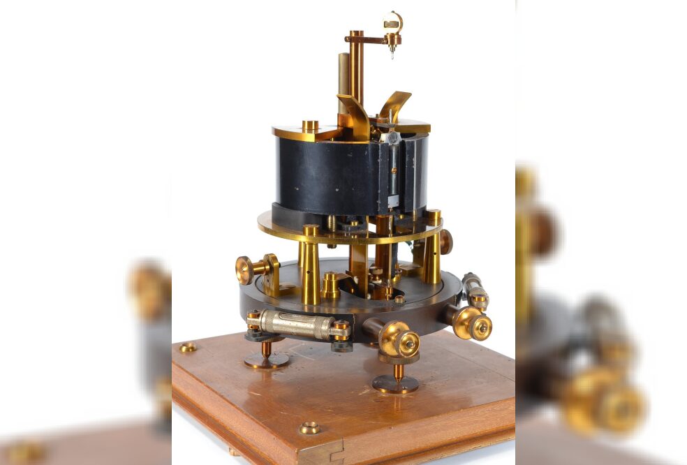
The first pointer meter used to detect current was called a galvanometer, invented in 1820. When used in conjunction with a Wheatstone Bridge, it can compare an unknown resistance and voltage to known voltages and resistances, thereby measuring related voltages, currents, and resistances. This method of measurement in the laboratory is time-consuming and labor-intensive, making it quite inconvenient. This device is cumbersome and not portable.
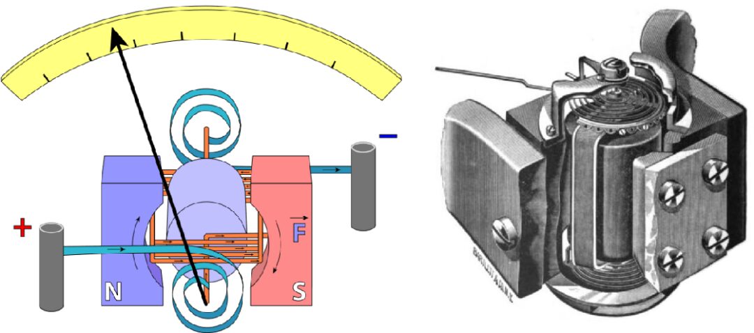
The galvanometer can only roughly indicate whether current exists but cannot provide an accurate value for the current. However, a current meter using a moving coil mechanism (D’Arsonval/Weston drive mechanism) can display the magnitude of the current.
A hollow coil wound with fine enameled wire is suspended within the poles of a permanent magnet, and when a direct current flows through it, it generates a torque that drives the pointer to rotate. The circular magnetic field is designed so that the ampere force on the current-carrying coil is independent of the angle, combined with a thin metal spring that generates a restoring torque, making the angle of the pointer’s rotation proportional to the current passing through the coil. This device is called the D’Arsonval drive mechanism, which is still widely used in various pointer-type analog electronic meters today.
Current meters based on the moving coil mechanism no longer require a Wheatstone Bridge and can easily and conveniently measure current. On this basis, by adding shunt resistors, series resistors, and stable direct current power supply, it is possible to measure voltages, currents, and resistances across different ranges.
In the 1920s, with the increasing use of electronic tube equipment, the multimeter was born. It is said that the first modern multimeter was invented by British Post Office engineer Donald Macadie in 1920.
In his work, to maintain communication facilities, he needed to continuously measure voltage, current, resistance, etc., in the circuits. He could no longer tolerate the hassle of carrying multiple meters, so he developed a multimeter that could measure voltage, current, and resistance, which was then called the Avometer.
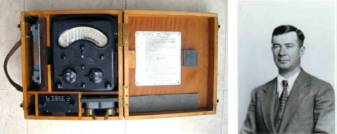
The Avometer used a moving coil mechanism pointer ammeter, equipped with precision voltage divider resistors and shunt resistors, using a range switch and sockets to select measurement categories and ranges.
Macadie transferred his design of the Avometer to the Automatic Winding and Electrical Equipment Company (ACWEEC, established in 1923), and it became a commercial product that same year. The Avometer, before the improved version 8, could only measure direct current voltage and current signals.
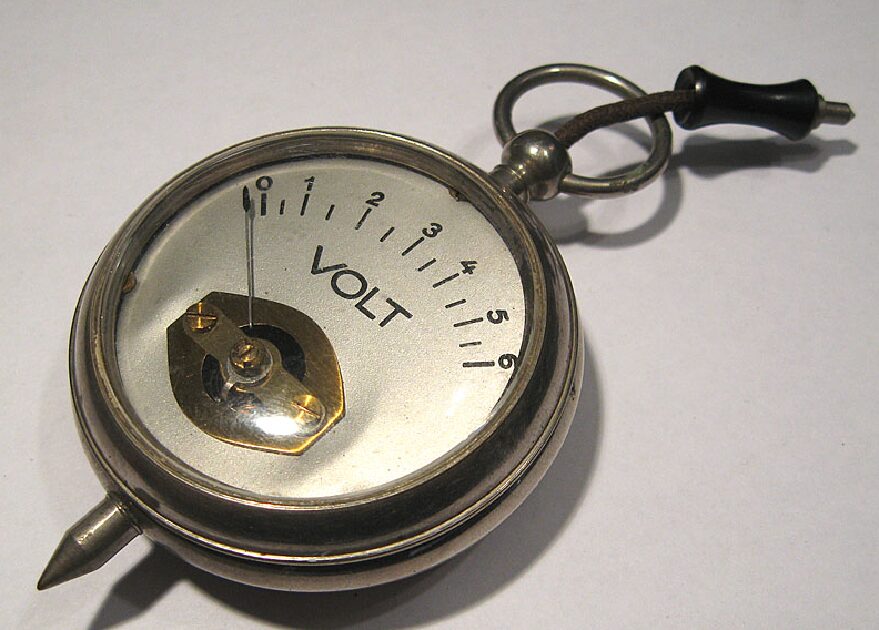
At that time, a pocket watch-style voltmeter was also popular, with a metal casing that was much cheaper than the Avometer. Its casing usually connected to the negative terminal of the meter. This simplification, while convenient, led many careless electronic engineers to suffer from electric shocks.
This type of meter was usually quite rudimentary, for example, the manual only indicated 33Ω/V, the scale was often not uniform, and there were no zero-adjustment screws for the pointer, etc.
Pointer-type multimeters usually need to draw a certain amount of current from the measured circuit to drive the rotating coil. For example, a full-scale 50 microamp meter head, commonly used high-sensitivity meter heads. During measurement, if the pointer is fully deflected, it needs to draw 50 microamps from the measured circuit, which can affect the measurement results of some high-impedance circuits, causing the read value to be lower than normal.
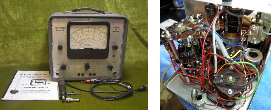
Using vacuum tubes to increase the input impedance of multimeters is very necessary; they are called vacuum tube voltmeters (VTVM, VVM). These electronic vacuum tube multimeters typically have an input impedance of over 1MΩ, utilizing the vacuum tube cathode follower output (voltage series negative feedback) circuit to increase input impedance, thus ensuring that the multimeter does not significantly affect the measured circuit during measurements.
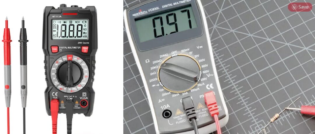
Before the invention of digital (integrated) multimeters, high-impedance analog transistor circuits, or field-effect transistors (FETs) were used to replace vacuum tubes in multimeter devices. Modern digital multimeters use high-impedance integrated circuits, with input impedances reaching or exceeding those of the original vacuum tube multimeters.
Today’s multimeters have added many additional features, such as decibel meters for measuring power, capacitance measurement, transistor gain, frequency, duty cycle, display hold, etc. The buzzer on the multimeter can emit sounds when measuring circuit continuity, providing quick measurement feedback. In conjunction with some special sensors, multimeters can also measure temperature, illuminance, etc., and come with computer interfaces. Some even have voice output functions for measurement values.

References
Multimeter – History: https://www.liquisearch.com/multimeter/history