Frame
The UART communication standard uses an 8-bit binary number as a frame, with the least significant bit first, transmitted bit by bit.
To distinguish each frame, a 0 is used as a start marker before each frame, followed by a 1 as a stop marker.
Before the stop marker, an optional “parity bit” can be sent, but most applications currently do not choose this bit.
Therefore, each serial communication transmits one byte, plus the start and stop markers, totaling 10 bits of binary data.
When idle, the signal is 1; once a 0 appears, it indicates the start of data transmission.
Baud Rate
An important metric of serial communication is the transmission speed, which indicates how many bits of binary data are transmitted per second.
This speed is called the baud rate, measured in bps, which means “bits per second” in Chinese.
Timing Settings
When transmitting data at 9600 bps, the duration of each bit is (1/9600)s, which is the interval time.
If the crystal oscillator frequency is 11059200Hz, the time for one machine cycle T is (12/11059200)s.
So, how many machine cycles T does the duration of one bit (1/9600)s equal? This is easy to calculate, as shown in the following equation:
X = (1/9600) / (12/11059200) = 11059200 / 12 / 9600 = 96T
To achieve precise timing, a timer can be used; whenever the time of 96T is reached, one binary bit can be sent out.
Sample Program
The program for simulating serial output using I/O ports is as follows:
#include<reg52.h>
sbit TXD1 = P2^0; // Simulate serial port transmitter using I/O port
sbit RXD1 = P2^1; // Simulate serial port receiver using I/O port
bit T96; // Bit variable
//—————————————-
void Wait96(void) // Delay to control baud rate
{
while(T96); // Wait for 0
T96 = 1; // Clear flag
}
//—————————————-
void WByte(char x) // Send one frame of data
{
char i;
TL0 = 160; // Initial value = 256-96=160
TXD1 = 0; // Send start bit 0
TR0 = 1; // Start timer
Wait96(); // Wait for 96T
for (i = 0; i < 8; i++) { // 8 bits
TXD1 = x & 1; // Transmit the low bit first
x >>= 1;
Wait96(); // Wait for 96T
}
TXD1 = 1; // Send stop bit 1
Wait96(); // Wait for 96T
TR0 = 0; // Stop timer
}
//—————————————-
void main()
{
char i;
TMOD = 0x02; // Timer 0 mode 2
TH0 = 160; // Initial value = 256-96=160
IE = 0x82;
T96 = 1; // Clear flag
while(1) {
for (i = 0x41; i < 0x5b; i++) // A~Z
WByte(i);
WByte(0x0D);
WByte(0x0A);
}
}
//—————————————-
void inttime0() interrupt 1 // Timer 0 interrupt
{
T96 = 0; // Set flag
}
//—————————————-
Simulation Screenshot
See the image below:
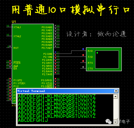
As seen in the image, the built-in serial port of the microcontroller was not used; instead, the virtual terminal was connected to port P2.
At this point, the virtual terminal also received characters A~Z, as well as carriage return and line feed.
Postscript
Simulating serial input using I/O ports is also feasible.
However, this simulation method results in a considerable workload in programming, and a significant amount of CPU time is consumed;
moreover, it also occupies the timer, which wastes many hardware resources.
If we discuss the reception issue of the simulated serial port, an external interrupt must also be included.
This clumsy method, I don’t know who thought of it initially! It truly pales in comparison to the method of expanding the serial port using tri-state gates introduced in the previous blog post.
After such effort, merely obtaining a serial port can be said to be not worth the loss.
Those who do and discuss will not use such a method; writing this blog post is merely to answer questions raised online.