Skip to content
When learning about in-vehicle testing, how can we not understand CAN basics? Today, I have organized a detailed note for everyone, so let’s follow along with Songqin!
CAN stands for Controller Area Network, which is an internationally standardized serial communication protocol by ISO. In simple terms, the CAN bus is a data transmission line used for transmitting data between different ECUs.
There are two ISO international standards for the CAN bus:ISO11898 and ISO11519.
* ISO11898 defines a high-speed CAN communication standard with a communication rate of 125 kbps to 1 Mbps, belonging to a closed-loop bus, with a transmission rate of up to 1 Mbps and a bus length of ≤ 40 meters.
* ISO11519 defines a low-speed CAN communication standard with a communication rate of 10 to 125 kbps, belonging to an open-loop bus, with a transmission rate of 40 kbps allowing a bus length of up to 1000 meters.
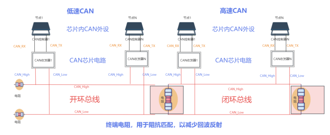
Based on the knowledge points introduced, I have roughly sketched the overall topology structure (as shown in the figure below), with the left side representing the topology structure of the low-speed CAN bus and the right side representing the topology structure of the high-speed CAN bus.
As shown in the figure, the CAN bus consists of two wires: CAN_H and CAN_L. Nodes are connected to the CAN bus through the CAN controller and CAN transceiver.
ECUs can integrate the CAN controller and transceiver, or they may not be integrated.
Introduction to CAN Signals
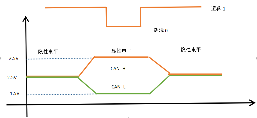
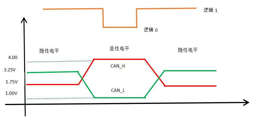
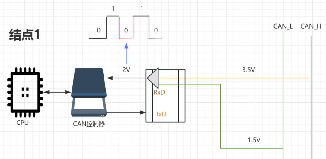
On the CAN bus, the potential difference between CAN_H and CAN_L is used to represent CAN signals. The potential difference on the CAN bus is divided into dominant level and recessive level. The dominant level represents logic 0, while the recessive level represents logic 1.
The representations of CAN signals in the ISO11898 standard (125 kbps ~ 1 Mbps) and ISO11519 standard (10 kbps ~ 125 kbps) are as follows:
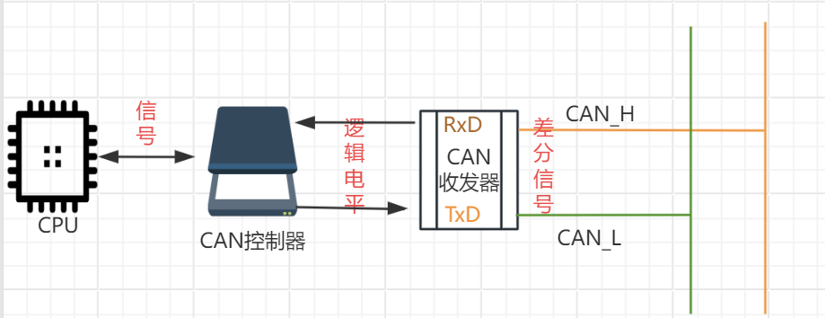
The CAN controller converts the signals from the CPU into logic levels (i.e., logic 0 – dominant level or logic 1 – recessive level). The CAN transmitter receives the logic level and then converts it into a differential level output to the CAN bus.
The CAN receiver converts the differential levels received on the CAN_H and CAN_L lines into logic levels and outputs them to the CAN controller, which then converts the logic level into the corresponding signal sent to the CPU.
The sender transmits its information to the CAN bus by changing the bus level.
The receiver listens to the bus level and reads the messages on the bus into its receiver.
Characteristics of CAN Communication
Multi-Master Operation Mode
The so-called multi-master operation mode means that all nodes on the bus have no distinction between master and slave; everyone is equal. This is reflected in data transmission as follows: In a bus idle state, any node can send messages to the bus.
In multi-master operation mode:
The first node to send a message to the bus obtains the right to send on the bus;
If multiple nodes send messages to the bus simultaneously, the node with the higher priority message obtains the right to send on the bus.
For example: If Node_A and Node_B send their respective messages Msg_1 and Msg_2 to the bus at the same time, and if Msg_1 has a higher priority than Msg_2, then Node_A obtains the right to send on the bus.
Non-destructive Bit Arbitration Mechanism
In the CAN protocol, all messages are sent using a fixed frame format. When multiple nodes send messages to the bus simultaneously, the identifiers (i.e., ID numbers) of each message are arbitrated bit by bit. If a node’s message wins the arbitration, that node will obtain the right to send on the bus, while the nodes that fail arbitration will immediately stop sending and switch to listening (receiving) mode.
For example: If Node_A and Node_B send their respective messages Msg_1 and Msg_2 to the bus at the same time, and the ID number ID_1 of Msg_1 and ID number ID_2 of Msg_2 are arbitrated bit by bit, if the arbitration result shows that ID_1 has a higher priority than ID_2, then Msg_1 wins the arbitration, and the node Node_A that sent Msg_1 obtains the right to send on the bus. At the same time, Msg_2 fails arbitration, and Node_B switches to listening to the bus level.
This arbitration mechanism neither causes delays to already sent data nor disrupts already sent data, so it is called a non-destructive arbitration mechanism. The implementation mechanism of this arbitration method is introduced in the second part of this series of notes on CAN protocol data frames and remote frames.
Flexibility of the System
Nodes on the CAN bus do not have the concept of “address,” so adding nodes to the bus does not affect the hardware and application layer of existing nodes on the bus.
All nodes on the same CAN line must have the same communication speed (bit rate). If nodes on two different communication speed buses want to exchange information, they must do so through a gateway.
For example: Generally, there are two CAN buses in a car: a 500 kbps drive system CAN bus and a 125 kbps comfort system CAN bus. If the engine node on the drive system CAN bus wants to send its speed information to the speedometer node on the comfort system CAN bus, these two buses must be connected through a gateway.
The CAN bus can achieve one-to-one, one-to-many, and broadcast data transmission modes, which depend on the acceptance filtering technology.
A certain node Node_A can request a certain node Node_B to send the message specified by that remote frame by sending a “remote frame” to the bus.
Error Detection, Notification, and Recovery Functions
All nodes can detect errors (error detection function); The node that detects an error will immediately notify all other nodes on the bus (error notification function); If a node that is sending a message detects an error, it will immediately stop the current transmission and continuously repeat sending this message until it is successfully sent (error recovery function).
Nodes can determine the type of error, whether it is a temporary data error (e.g., noise interference) or a persistent data error (e.g., internal node failure). If it is determined to be a serious persistent error, the node will cut off its connection to the bus to avoid affecting the normal operation of other nodes on the bus. The characteristics of CAN communication mentioned above are all implemented based on various frame structures defined by the CAN protocol.
CAN Communication Network Structure
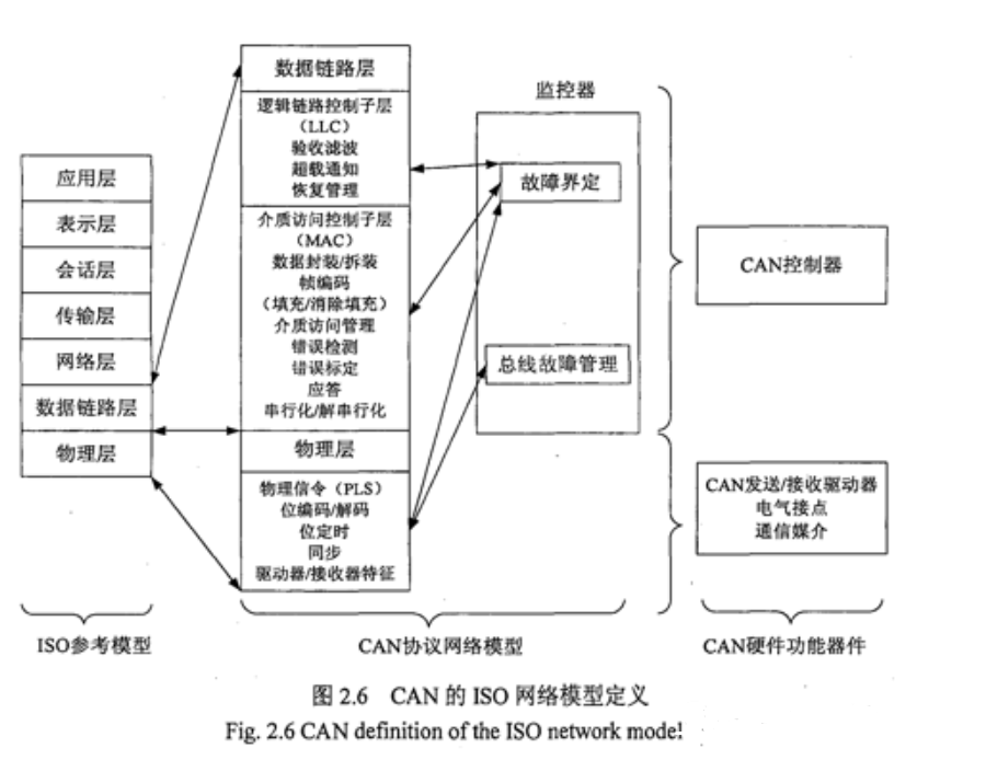
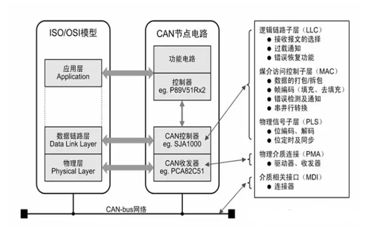
OSI Basic Reference Model
In fact, the CAN bus network only uses the data link layer and transport layer of the OSI basic reference model at the bottom layer. In the upper layer of the CAN network, only the application layer of the OSI basic reference model is used.
That’s all for the basics of CAN! After reading, do you have a better understanding? This week, we are starting the in-vehicle testing course. If you want to follow the live course to learn about in-vehicle testing, don’t miss it!