▍Overview
CAN (Controller Area Network) is a serial communication network that enables distributed real-time control.
When thinking of CAN, one must think of Bosch, the German company that developed it (along with Intel).
CAN has many excellent features that allow it to be widely used. For example: a maximum transmission speed of 1 Mbps, a maximum communication distance of 10 km, a lossless arbitration mechanism, and a multi-master structure.
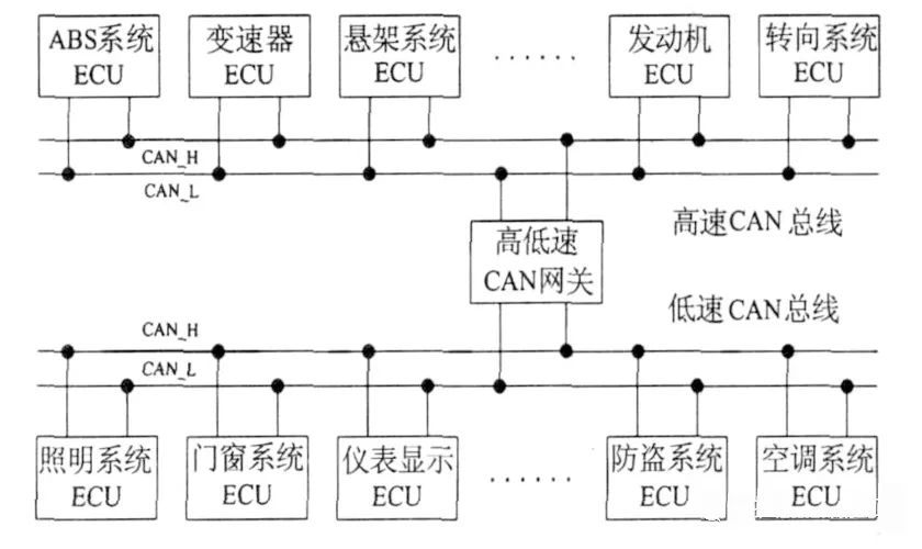
In recent years, the price of CAN controllers has decreased significantly, and many MCUs have integrated CAN controllers. Nowadays, every car is equipped with a CAN bus.
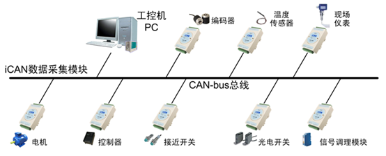
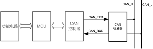
A typical application scenario for CAN:
▍CAN Bus Standards
The CAN bus standard only specifies the physical layer and data link layer, requiring users to define the application layer. Different CAN standards differ only in the physical layer.
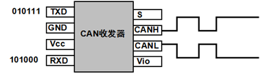
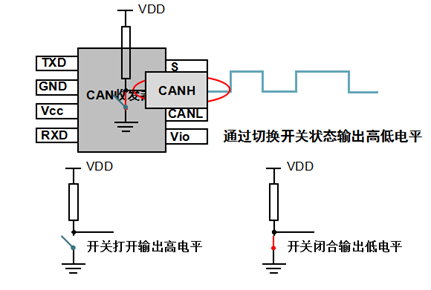
The CAN transceiver is responsible for converting between logical levels and physical signals.
It converts logical signals into physical signals (differential levels) or converts physical signals into logical levels.
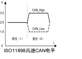
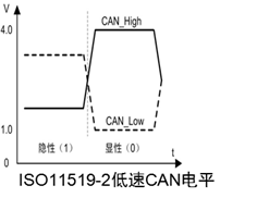
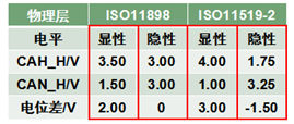
There are two CAN standards: ISO11898 and ISO11519, each with different differential voltage characteristics.
Low and high voltage amplitudes are low, corresponding to fast transmission speeds;
*Twisted pair eliminates common mode interference because the levels change simultaneously, while the voltage difference remains unchanged.
Physical Layer
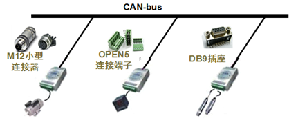
There are three types of interface devices for CAN.
Multiple nodes are connected; as long as one is low, the bus is low. The bus is only high when all nodes output high. This is called “wired AND”.
After five consecutive identical bits on the CAN bus, an opposite bit is inserted to create a transition edge for synchronization, eliminating accumulated errors.
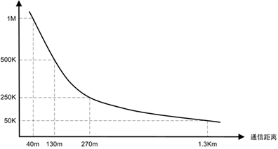
Like RS-485 and RS-232, the transmission speed of CAN is inversely proportional to the distance.
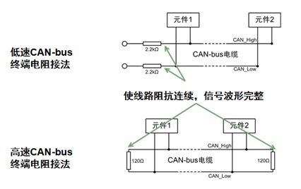
CAN bus, connection method of terminal resistors:
Why 120Ω? Because the characteristic impedance of the cable is 120Ω, simulating an infinitely long transmission line.
Data Link Layer
The CAN bus transmits CAN frames, which are divided into five types: data frames, remote frames, error frames, overload frames, and frame intervals.
Data frames are used for data transmission between nodes and are the most commonly used frame type; remote frames are used for receiving data from the sending node; error frames notify other nodes of frame errors; overload frames inform the sending node of the receiving node’s capacity; frames that isolate data frames and remote frames from previous frames.
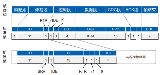
Data frames are divided into standard frames (2.0A) and extended frames (2.0B) based on the arbitration segment length.
Frame Start
The frame start consists of a dominant bit (low level). The sending node sends the frame start, and other nodes synchronize to it;
The frame end consists of seven recessive bits (high level).
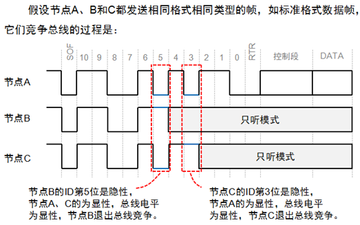
Arbitration Segment
How does the CAN bus solve the problem of multi-point competition?
The arbitration segment provides the answer.
The CAN bus controller monitors the bus level while sending data. If the levels differ, it stops sending and takes other measures. If the bit is in the arbitration segment, it exits the bus competition; if in other segments, it generates an error event.
The smaller the frame ID, the higher the priority. Since the RTR bit of the data frame is dominant and the remote frame is recessive, under the same frame format and ID, data frames take priority over remote frames; since the IDE bit of the standard frame is dominant and that of the extended frame is recessive, for the first 11 bits of ID, standard frames have a higher priority than extended frames.
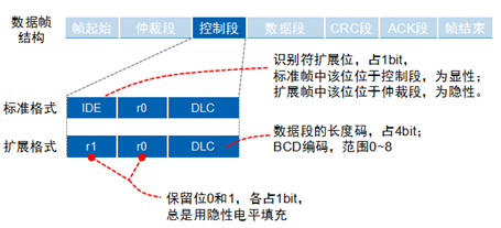
Control Segment
It consists of six bits. The control segment of the standard frame includes the extended frame flag IDE, reserved bit r0, and data length code DLC; the control segment of the extended frame consists of IDE, r1, r0, and DLC.
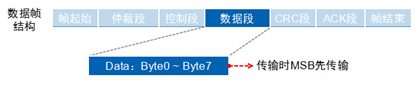
Data Segment
It ranges from 0 to 8 bytes, with a short frame structure and good real-time performance, suitable for automotive and industrial control fields;
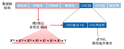
CRC Segment
The CRC check segment consists of a 15-bit CRC value and CRC delimiter.
ACK Segment
When the receiving node has received the frame start to the CRC segment without error, it sends a dominant level in the ACK segment, while the sending node sends a recessive level, resulting in a dominant level on the line.
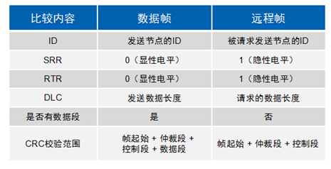
Remote Frame
The remote frame consists of six segments and is divided into standard and extended frames, with the RTR bit being 1 (recessive level).
CAN is a highly reliable bus, but it also has five types of errors.
CRC Error: This error occurs when the CRC values sent and received differ;
Format Error: This error occurs when the frame format is invalid;
Acknowledge Error: This error occurs when the sending node does not receive acknowledgment during the ACK phase;
Bit Send Error: This error occurs when the sending node finds that the bus level does not match the sending level while transmitting information;
Bit Stuffing Error: This error occurs when communication rules are violated on the communication cable.
When one of these five errors occurs, the sending or receiving node will send an error frame.
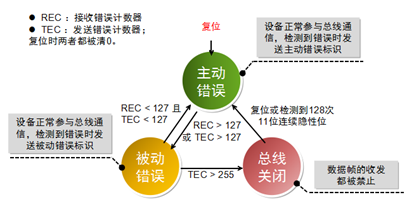
To prevent certain nodes from continually sending error frames and interfering with communication with other nodes, the CAN protocol stipulates three states and behaviors for nodes.
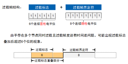
Overload Frame
When a node is not ready to receive, it will send an overload frame to notify the sending node.
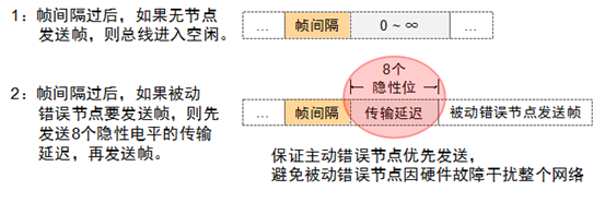
Frame Interval
Used to isolate data frames, remote frames, and their preceding frames; error frames and overload frames are not preceded by frame intervals.
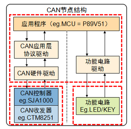
Building CAN Nodes
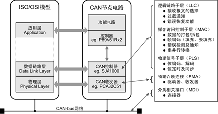
Building nodes to achieve control, divided into four parts from bottom to top: CAN node circuit, CAN controller driver, CAN application layer protocol, CAN node application program.
Although different nodes perform different functions, they all share the same hardware and software structure.
The CAN transceiver and controller correspond to the physical layer and data link layer of CAN, completing the transmission and reception of CAN messages; functional circuits complete specific functions, such as signal acquisition or controlling peripherals; the main controller and application software parse messages according to the CAN message format to achieve corresponding control.
The CAN hardware driver is a program running on the main controller (such as P89V51) that mainly performs the following tasks: register-based operations, initializing the CAN controller, sending CAN messages, and receiving CAN messages;
If the CAN hardware driver is used directly, when changing controllers, modifications are needed in the upper-layer application, leading to poor portability. Adding a virtual driver layer between the application layer and hardware driver layer can mask the differences between different CAN controllers.
A CAN node not only performs communication functions but also includes some specific hardware functional circuits. The functional circuit driver directly controls the functional circuit downward and provides control function circuit function interfaces to the application layer upward. Specific functions include signal acquisition, human-machine display, etc.
CAN transceivers implement the interchange between the logical levels of the CAN controller and the differential levels on the CAN bus. There are two schemes for implementing CAN transceivers: one is using CAN transceiver ICs (requiring power and electrical isolation), and the other is using CAN isolation transceiver modules. The latter is recommended.
The CAN controller is the core component of CAN, implementing all functions of the data link layer in the CAN protocol and automatically completing the parsing of the CAN protocol. There are generally two types of CAN controllers: controller ICs (SJA1000) and MCUs (LPC11C00) with integrated CAN controllers.
The MCU is responsible for controlling the functional circuits and CAN controller: initializing the CAN controller parameters at node startup; reading and sending CAN frames through the CAN controller; handling CAN controller interrupt exceptions when they occur; outputting control signals based on received data;
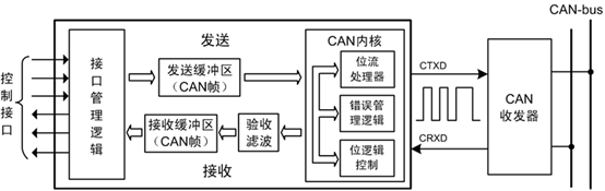
Interface management logic: interprets MCU instructions, addresses the register units of various functional modules in the CAN controller, and provides interrupt and status information to the main controller.
The send buffer and receive buffer can store complete information on the CAN bus network.
Acceptance filtering compares the stored verification code with the CAN message identifier; only the CAN frames matching the verification code will be stored in the receive buffer.
The CAN kernel implements all protocols of the data link.
▍Overview of CAN Protocol Application Layer
The CAN bus only provides reliable transmission services, so when nodes receive messages, they must use application layer protocols to determine who sent the data and what the data represents. Common CAN application layer protocols include: CANOpen, DeviceNet, J1939, iCAN, etc.
The CAN application layer protocol driver is a program running on the main controller (such as P89V51) that defines CAN messages according to the application layer protocol, completing the parsing and assembly of CAN messages. For example, we use the frame ID to represent the node address, and when the received frame ID does not match the node ID, it is discarded; otherwise, it is passed to the upper layer for processing; when sending, the frame ID is set to the address of the receiving node.
(Images and texts are sourced from the internet)
Click the mini-program below to see more repair cases