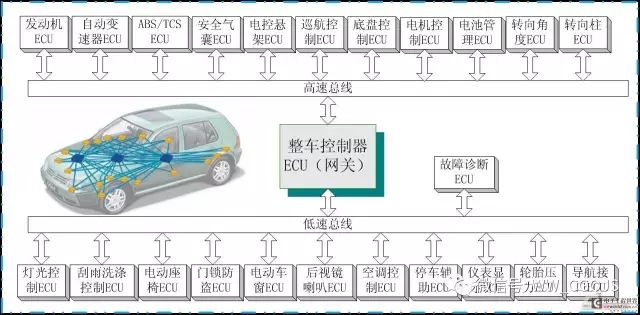
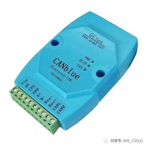
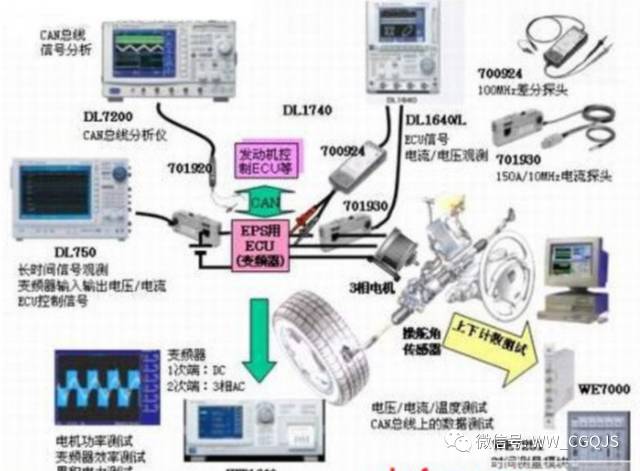
CAN, short for “Controller Area Network”, is one of the most widely used field buses internationally. Initially, CAN was designed for microcontroller communication in automotive environments, exchanging information between various electronic control units (ECUs) in vehicles, forming an automotive electronic control network. For example, the engine management system, transmission controller, instrument equipment, and electronic backbone system all embed CAN control devices.
In a single network constructed by the CAN bus, theoretically, countless nodes can be connected. In practical applications, the number of nodes is limited by the electrical characteristics of the network hardware. CAN can provide data transmission rates of up to 1 Mbit/s, making real-time control very easy. Additionally, the hardware’s error detection characteristics enhance CAN’s resistance to electromagnetic interference.
Principles of CAN Bus Technology
CAN bus uses a serial data transmission method, operating at a rate of 1 Mb/s over 40m twisted pair cables, and can also use optical cables for connection. Moreover, the bus protocol supports multiple master controllers. CAN is similar to the I2C bus in many details, but there are also some obvious differences.
When a node (station) on the CAN bus sends data, it broadcasts the message to all nodes in the network. For each node, regardless of whether the data is intended for itself, it will receive the message.
Each message begins with an 11-bit identifier, defining the message’s priority. This message format is called a content-addressed scheme. In the same system, the identifier is unique, and it is impossible for two stations to send messages with the same identifier. This configuration is crucial when several stations simultaneously compete for bus access.

When a station wants to send data to other stations, its CPU will send the data and its identifier to the CAN chip at that station and prepare to send. When it receives bus allocation, it switches to sending message mode.
The CAN chip organizes the data into a specific message format according to the protocol, at which point other stations on the network are in receiving mode. Each receiving station checks the received message to determine whether it is intended for itself to decide whether to accept it.
Since CAN bus is a content-addressed scheme, it is easy to establish a high-level control system and configure it flexibly. We can easily add new stations to the CAN bus without modifying hardware or software.
When the newly added station is purely a data-receiving device, the data transmission protocol does not require an independent physical address for the station. It allows for the synchronization of data acquisition processes, meaning that when controllers on the bus need to measure data, it can be obtained from the network without each controller having its own independent sensors.
CAN Supports Four Types of Information Frames
1. Data Frame
The CAN protocol has two types of data frame standards: 2.0A and 2.0B. The essential difference between the two lies in the length of the ID. In the 2.0A type, the ID length is 11 bits; in the 2.0B type, the ID is 29 bits. A message frame consists of seven main fields: frame start field – a single dominant bit indicating the start of the data frame.
The arbitration field – consists of the identifier and the Remote Transmission Request (RTR) bit, which indicates whether this information frame is a data frame or a remote request frame without any data. When data frames of 2.0A and 2.0B types must be transmitted on the same bus, priority is first determined, and if the IDs are the same, the non-extended data frame has higher priority than the extended data frame.
The control field – r0, r1 are reserved bits, serving as extension bits, and DLC indicates the number of data bytes in a frame. The data field – contains 0 to 8 bytes of data.
The CRC field – a 15-bit cyclic redundancy check used for error checking. The acknowledgment field – includes the acknowledgment bit and acknowledgment delimiter. The receiving station that correctly receives a valid message will set the bus value to a dominant level during the acknowledgment period. Frame end – consists of seven recessive bits.
2. Remote Frame
The receiving node of a remote frame can request the source node to send data. It consists of six fields: frame start, arbitration field, control field, CRC field, acknowledgment field, and frame end.
3. Error Frame
The error frame consists of the error flag and the error delimiter fields. When a receiving node detects an error in a message on the bus, it will automatically send an “active error flag”. Other nodes detecting the active error flag will send an “error acknowledgment flag”.
4. Overload Frame
The overload frame consists of the overload flag and the overload delimiter. An overload frame can only start after a frame end. When the receiver needs excessive time to process the current data before receiving the next frame, or detects a dominant level in the inter-frame gap, it will send an overload frame.
5. Inter-frame Gap
The inter-frame gap exists between data frames and remote frames and the preceding information frame, consisting of the inter-frame gap and the bus idle state. The inter-frame gap is necessary, during which CAN does not send new frames, allowing the CAN controller time for internal processing before the next information transfer. The CAN controller can only send data when the bus is idle.
The Development History of CAN Bus
In the early 1980s, engineers from Bosch started to demonstrate the feasibility of serial buses for bus systems. Since no existing network solution could fully meet the requirements of automotive engineers, in early 1983, Uwe Kiencke began researching a new serial bus.
The main direction of the new bus was to increase new functions and reduce electrical connections, making it applicable to products. Engineers from Mercedes-Benz were among the first to develop the state description of the bus, while Intel also prepared to be a major semiconductor manufacturer.
In February 1986, CAN was born. At the automotive engineering association meeting in Detroit, the new bus system researched by Bosch was called “Automotive Serial Controller Area Network”. Uwe Kiencke, Siegfried Dais, and Martin Litschel introduced this multi-master network scheme.
This scheme is based on a non-destructive arbitration mechanism that ensures the transmission of high-priority messages without delay. Furthermore, there is no need to set a master controller on the bus. Additionally, the fathers of CAN – the aforementioned professors along with Wolfgang Borst, Wolfgang Botzenhard, Otto Karl, Helmut Schelling, and Jan Unruh from Bosch have implemented several error detection mechanisms in CAN.
This error detection also includes the automatic disconnection of faulty nodes to ensure continued communication among the remaining nodes. The transmitted messages are identified not by the sender/receiver node address but by the content of the message. Meanwhile, the identifier used to identify the message also defines its priority in the system.
After most of the textual content regarding this revolutionary communication scheme was established, in mid-1987, Intel delivered the first CAN controller, 82526, two months ahead of schedule, marking the first hardware realization of the CAN scheme. It took only four years for the concept to become a reality.
Shortly afterward, Philips Semiconductor launched the 82C200. These two earliest CAN controllers had many differences in acceptance filtering and message control. On one hand, the FullCAN promoted by Intel had a lower CPU load than the BasicCAN promoted by Philips; on the other hand, the number of messages that FullCAN devices could receive was relatively limited, while BasicCAN controllers required fewer silicon crystals.
Today, the “descendants” of CAN controllers still have considerable differences in acceptance filtering and message control within the same module, creating two major camps: BasicCAN and FullCAN.
Standardization and Consistency.
Although the initial research on CAN started with its application in bus systems, the first market application of CAN came from other fields. Particularly in Northern Europe, CAN has been widely used. In the Netherlands, elevator manufacturers Kone use the CAN bus.
The Swiss engineering office Kvaser has suggested applying CAN to some textile machinery manufacturers (Lindauer Dornier and Sulzer), providing communication protocols for their machines. In this field, under the leadership of Lars-Berno Fredriksson, the company established the “CAN Textile Machinery User Group”.
By 1989, they had researched communication principles and helped establish the “CAN Kingdom” development environment in early 1990. Although CAN Kingdom is not an application layer based on the OSI reference model, it is considered a prototype of high-level protocols based on CAN.
In the Netherlands, Philips Medical Systems decided to use CAN to form the internal network of X-ray machines, becoming an industrial user of CAN. Most pioneers of CAN used single-chip circuits, combining communication functions, network management, and application code in the same software. Even though some users had many standard modules available, they still faced defects in all solutions.
In the early 1990s, a plan was initiated to establish a user organization to standardize different solutions.
J1939, another application sub-protocol based on CAN, was formulated by the SAE Truck and Bus Association. J1939 is a non-modular scheme, easy to learn but with poor flexibility. Of course, the 15 semiconductor manufacturers producing CAN module integration devices primarily focus on the automotive industry.
Since the mid-1990s, Infineon and Motorola have provided numerous CAN controllers to European bus manufacturers. From the late 1990s, semiconductor manufacturers in the Far East also began to provide CAN controllers. In 1994, NEC launched the CAN chip 72005.
Since 1992, Mercedes-Benz has begun using CAN technology in their high-end buses. The first step was to manage the engine through electronic controllers via CAN; the second step was to use controllers to receive operational signals. This involved two physically independent CAN bus systems connected via a gateway. Other bus manufacturers flocked to Stuttgart to learn and also implemented two sets of CAN bus systems in their buses.
Despite the long history of the CAN protocol, it is still being improved. An ISO task organization composed of several companies has defined a time-triggered CAN message transmission protocol. Currently, CAN still occupies an initial position in the global market, as automotive manufacturers will use CAN in the serial components of the cars they produce.
Moreover, there is a robust growth in demand for special security systems combined with high-level protocol applications based on CAN, as many potential new applications (e.g., entertainment) are emerging – not only for automobiles but also for household consumption. The German professional committee BIA and the German safety standard authority TÜV have certified some security systems based on CAN.
The Layered Structure of CAN Bus
CAN complies with the OSI model, and according to the OSI reference model, the CAN structure is divided into two layers: the data link layer and the physical layer, as shown in the figure below.
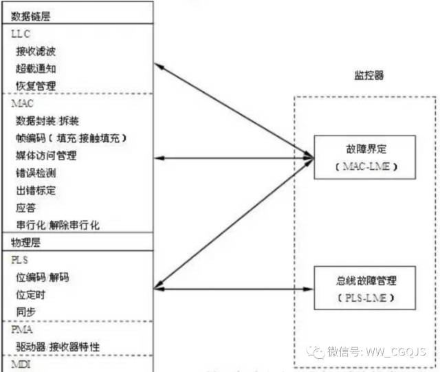
The data link layer is further divided according to IEEE 802.2 and 802.3 standards:
1. Logical Link Control (LLC-Logic Link Control).
2. Medium Access Control (MAC-Medium Access Control).
The physical layer is further divided into:
1. Physical Signaling (PLS-Physical Signalling).
2. Physical Medium Attachment (PMA-Physical Medium Attachment).
3. Medium Dependent Interface (MDI-Medium Dependent Interface).
The MAC sub-layer operates under the supervision of a management entity called the “Fault Confinement Entity (FCE)”. Fault confinement is a self-checking mechanism that enables the distinction between transient disturbances and permanent faults. The physical layer can be monitored through detection and management of physical media fault entities (e.g., bus short circuits or interruptions, bus fault management).
LLC and MAC, two equal protocol entities, exchange frames or Protocol Data Units (PDU) and (N)-user data to form an NPDU. For an NPDU, (N-1) layer entities must access through (N-1) service access points [(N-1)-SAP]. The NPDU is transmitted to the (N-1) layer via (N-1) layer Service Data Units (SDU) [(N-1)-SDU], whose service functions allow the NPDU’s transmission.
SDU is interface data, identified in advance among (N) layer entities, meaning it represents logical data units transmitted by the service. The data link layer of the CAN protocol does not provide a method for assigning an SDU to multiple PDUs, nor for assigning multiple SDUs to one PDU, meaning that the NPDU consists directly of the corresponding NSDU and layer-specific control information N-PCI.
Characteristics of CAN Bus
CAN has excellent characteristics that make it a preferred choice. These advantages include:
1. Multi-master Control
When the bus is idle, all units connected to the bus can initiate sending information. This is known as the concept of multi-master control.
The device that occupies the bus first obtains the qualification to send information on the bus. This is known as the CSMA/CR (Carrier Sense Multiple Access/Collision Avoidance) method.
If multiple devices start sending information simultaneously, the device sending the message with the highest priority ID obtains the right to send.
2. Information Transmission
In the CAN protocol, all information sent must meet a predefined format. When the bus is not occupied, any device connected to the bus can initiate the transmission of new information. If two or more devices initiate information transmission simultaneously, priority is determined by the ID. The ID does not specify the destination of the information sent but indicates the priority of the information.
If two or more devices initiate information transmission at the same time, they compete based on each bit of the ID included in the information. The winning device (i.e., the one with the highest priority information) can continue to send, while the losers immediately stop sending and enter receiving mode. Since there can only be one sender on the bus at the same time, while others are in receiving mode, there is no need to define the concept of addressing in the lower-level protocol.
3. System Flexibility
Units connected to the bus do not have identifiers like addresses, so adding or removing a device does not require changes to hardware or software, or the application layer software of other devices.
4. Communication Speed
Any communication speed can be set to suit the network scale.
For a network, all units must have the same communication speed; if different, errors will occur, hindering network communication. However, different networks can have different communication speeds.
5. Remote Data Request
Data can be requested from other units by sending a “remote frame”.
6. Error Detection, Notification, and Recovery Functions
All units can detect errors (error detection function). The unit detecting an error immediately notifies all other units (error notification function). If a unit detects an error while sending information, it will forcibly terminate the information transmission and notify all other devices of the error, then it will retransmit until the information is transmitted correctly (error recovery function).
7. Error Isolation
There are two types of errors on the CAN bus: transient errors (data on the bus temporarily erroneous due to noise) and permanent errors (caused by internal device failures, such as a faulty driver or connection issues). CAN can distinguish between these two types, lowering the communication priority of frequently erroneous units to prevent affecting other normal devices. On the other hand, if it is a permanent error, the device will be isolated from the bus.
8. Connectivity
CAN bus allows multiple devices to be connected to the bus simultaneously, with no logical limit on the number of connections. However, due to delays and load capacity limitations, the actual number of connectable devices is restricted. The number of connected devices can be increased by lowering the communication speed. Conversely, if there are fewer connected devices, the communication speed can be increased.
Comparison of CAN with Other Communication Solutions
The differences between CAN bus and other communication networks are:
Firstly, the message transmission does not include a target address; it is based on broadcasting across the entire network. Each receiving station filters messages based on the identifiers reflecting the nature of the data in the message, accepting what it should and discarding what it should not. The benefits are plug-and-play and multi-station reception, both online and offline;
Secondly, it particularly enhances attention to data security, meeting the demands of control systems and other systems requiring higher data integrity.
In practice, there are two important bus allocation methods: scheduled allocation and demand allocation. In the first method, each node is allocated a maximum period regardless of whether it applies for bus access. Thus, the bus can be allocated uniquely to each station, regardless of whether it accesses the bus immediately or at a specific time.
This ensures clear bus allocation during bus access. In the second method, the bus is allocated to a station based on the fundamental requirements for data transmission, and the bus system allocates according to the station’s desired transmission. Therefore, when multiple stations request bus access simultaneously, the bus will terminate all stations’ requests, and none will gain bus allocation. More than one bus access is necessary to allocate the bus.
The method of bus allocation implemented by CAN ensures that when different stations request bus access, the allocation is conducted clearly. This bit arbitration method can resolve the collision problem that arises when two stations send data simultaneously. Unlike message arbitration in Ethernet networks, CAN’s non-destructive method of resolving bus access conflicts ensures that the bus is not occupied when no useful messages are being sent.
Even when the bus is under heavy load, bus access based on message content has proven to be an effective system. Although the bus’s transmission capacity is insufficient, all unresolved transmission requests are processed in order of importance. In networks such as CSMA/CD, like Ethernet, the system often crashes due to overload, which does not happen in CAN.
Applications of CAN Bus
The advantages of CAN bus in networking and communication functions, along with its high cost-performance ratio, determine its broad application prospects and development potential in many fields. These applications share commonalities: CAN essentially serves as a computer local area network for bus topology in the field.
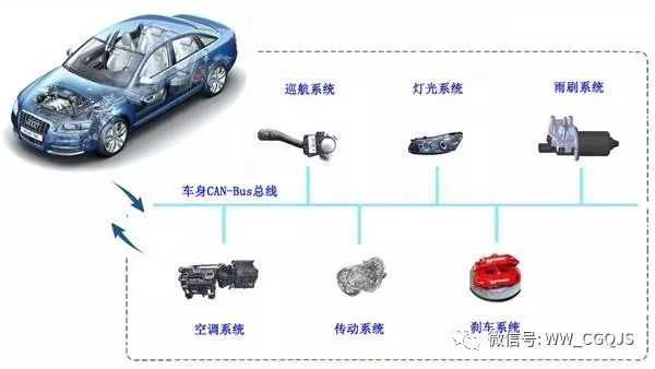
Regardless of the occasion, it burdens real-time communication between any nodes, but it possesses advantages such as simple structure, high speed, interference resistance, reliability, and low cost. The CAN bus was initially designed for automotive electronic control systems, and its application has become very common in vehicles produced in Europe. Moreover, this technology has been extended to trains, ships, and other transportation tools.
Using the CAN bus can reduce wiring in the vehicle body, further saving costs. With bus technology, signal transmission between modules requires only two signal lines. Wiring is localized, and all other wires that run across the vehicle body are no longer needed, saving wiring costs.
CAN bus system data is stable and reliable, with low inter-wire interference and strong anti-interference capabilities. The CAN bus is tailor-made for automobiles, fully considering the harsh working environment in vehicles, such as the strong back EMF generated during ignition coil firing, the surge current when the electric coil buffer is cut off, and the high temperatures around 100°C in the engine compartment.
As safety performance receives increasing attention, the number of airbags will gradually increase. Previously, only one was installed in front of the driver, but in the future, side and rear airbags will also be installed. These airbags sense collision signals through sensors and transmit the sensor signals to a central processor via the CAN bus, controlling the deployment of each airbag.
At the same time, advanced anti-theft designs are also based on CAN bus network technology. First, the verification information confirming the legality of the key is transmitted through the CAN network, improving the encryption algorithm, making the verification information richer than previous anti-theft systems; secondly, the car key, anti-theft controller, and engine controller store each other’s information, and the verification code is mixed with random codes, making it impossible to decipher, thus enhancing the security of the anti-theft system. The realization of these functions relies entirely on the CAN bus, making it the “anchor” of intelligent control in automobiles.
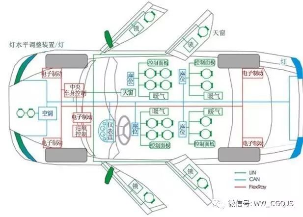
In modern car design, CAN has become a necessary device. Brands like Mercedes-Benz, BMW, Volkswagen, Volvo, and Renault have adopted CAN as a means of networking controllers. Reports indicate that China’s first hybrid car with a CAN network system has been successfully trial-installed by Chery and has undergone preliminary trial runs.
In Shanghai Volkswagen’s Passat and POLO cars, CAN bus technology has also begun to be introduced. However, overall, the application of CAN bus technology in China’s automotive industry is still at the experimental and initial stages, with the vast majority of cars not yet adopting automotive bus designs. It is imperative to deepen the “study” of network buses in terms of technology, design, and application domestically.
Application in Large Instruments and Equipment
Large instruments and equipment are complex systems that refer to various information collection, processing, control, and output operations according to certain steps. In the past, the electronic systems of such instruments and equipment often occupied a considerable part in terms of structure and cost, and their reliability was not high. After adopting CAN bus technology, there have been significant improvements in this regard.
Taking medical equipment as an example, a pathological distributed monitoring system consists of a central control monitoring unit and field collection units. The field collection units perform real-time data and image collection from diagnostic measuring instruments in various hospital rooms, while also completing data statistics and storage; the central monitoring unit can periodically or irregularly obtain data from the field collection units and complete image monitoring, data statistics, report generation, and database management.
The central monitoring unit and field collection units are connected together via the CAN bus, with the central monitoring unit in a master control position, while the field collection units can respond to commands from the central monitoring unit at any time. Each field collection unit consists of a microcontroller 8C552 and modules for collection, storage, display, remote control, and communication, and each field collection unit can connect to 10 measuring instruments.
CAN bus is designed for measurement and control fields, so the amount of data transmitted in one message is small, with a maximum data limit of 8 bytes per message. This small data transmission volume can facilitate the transmission of low-priority transactions while also meeting measurement and control needs. Given the many advantages of CAN bus technology, it is very suitable for communication between modular components in large instrument systems, constructing large instrument systems using modular networking.
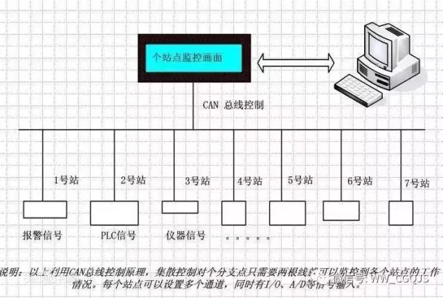
Application in Industrial Control
With the development of computer technology, communication technology, and control technology, the traditional industrial control field is undergoing an unprecedented transformation, and the networking of industrial control expands the development space of industrial control and brings new development opportunities. In a wide range of industrial fields, CAN bus can serve as a communication bus at the field device level, and compared to other buses, it has high reliability and performance-price ratio. This will be a major direction for CAN technology development and application.
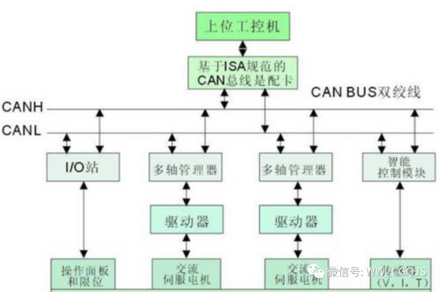
For example, a Swiss company has developed an axis control system ACS-E that has a CAN interface. This system can serve as a slave in the industrial control network, controlling machine tools, robots, etc. On one hand, it communicates with the upper computer over the CAN bus, while on the other hand, it can control digital servo motors via the CAN bus. Up to six digital servo motors can be connected through the CAN bus.
Currently, the application of CAN bus technology in engineering machinery is becoming more and more common. Some well-known international engineering machinery companies such as CAT, VOLVO, Liebherr, and Haier have widely adopted CAN bus technology in their products, greatly improving the reliability, detectability, and maintainability of the entire machine, while also enhancing the level of intelligence. In China, CAN bus control systems have also begun to be widely used in the control systems of engineering vehicles and are gradually being promoted in the engineering machinery industry.
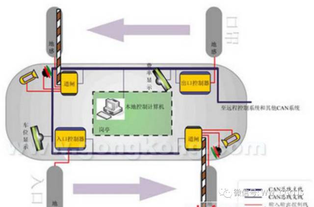
Application in Smart Homes and Community Management
Community intelligence is a comprehensive system engineering that must consider multiple aspects such as functionality, performance, cost, expansion capability, and the application of modern related technologies. Based on such demands, the smart home management system designed using CAN technology is suitable for applications in multi-meter remote transmission, anti-theft, fire prevention, gas leak detection, emergency rescue, and home appliance control, among others.
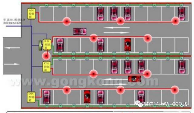
CAN bus is part of the community management system, responsible for collecting various data and signals from households and sending them to the community management center for processing. The nodes on the CAN bus include the household control unit, the community’s three-meter reading system, and the alarm monitoring system. Each household’s control system can send alarm signals via the bus, regularly sending three-meter data to the automatic meter reading system, and receiving announcements from the community management system, such as overdue payment notifications and fire alarms.
This system fully utilizes the characteristics and advantages of CAN technology to form a smart detection system for residential communities, integrating functions such as multi-meter collection, anti-theft alarms, water and electricity control, emergency assistance, gas leak alarms, fire alarms, and power supply monitoring subsystems, while providing remote communication services.
Application in Robot Networking
The automation of bottom-level equipment in manufacturing workshops has remained a primary area for research and application of new technologies and product development in recent years, with market demand continuously increasing and becoming more active, leading to increasingly fierce competition. With the industrialization of industrial robots, the application of robot systems often requires network interconnection among multiple robots.
Consequently, in practical production processes, the scheduling and maintenance of this connected multi-robot system have also become particularly important. Networking of electrical devices at the bottom level of manufacturing workshops has become a focus of technological development in recent years.
These electrical devices include motion controllers, microprocessor-based sensors, dedicated equipment controllers, and other bottom-level devices; on the network formed by these devices, there are also non-bottom-level devices such as workshop-level management machines, monitoring machines, or production unit controllers. Based on actual situations and requirements, the robot controller can be regarded as a motion controller.
By fully applying CAN bus technology to existing controllers, it is possible to develop a high-performance multi-robot production line system. Utilizing existing control technology, combined with CAN technology and communication technology, by making hardware improvements and software development to existing robot controllers, and correspondingly developing upper computer monitoring software, a network interconnection of multiple robots can be achieved.
Ultimately, a robot production line integration system based on the CAN network can be realized. This approach has many benefits, such as achieving a single cable connecting all devices, saving installation and maintenance costs; improving real-time performance, allowing information sharing; enhancing the detection, diagnosis, and control performance of multi-controller systems; and completely detaching some personnel from the robot worksite through offline task scheduling, job downloading, and error monitoring technologies.
CAN bus data communication is characterized by outstanding reliability, real-time performance, and flexibility. Due to its excellent performance and unique design, CAN bus is receiving increasing attention, and its application in the automotive field is the most extensive. Most of the world’s renowned automotive manufacturers have adopted CAN bus to enable data communication between the internal control systems of cars and various detection and execution mechanisms.
At the same time, due to the characteristics of the CAN bus itself, its application scope is no longer limited to the automotive industry but is expanding into fields such as automatic control, aerospace, maritime, process industry, mechanical engineering, textile machinery, agricultural machinery, robotics, CNC machine tools, medical devices, and sensors. CAN has formed international standards and is recognized as one of the most promising field buses.
– END –
Source: Sensor Technology

Previous Articles
Open Access | Measurement and Control Technology, 2020, Volume 39, Issue 8, Special Issue on Machine Vision Technology
Academician Tan Jiubin of the Chinese Academy of Engineering: The Core Key is to Solve the Problem of Ultra-Precision Measurement Capability
Notice on the Call for Papers for the 2020 Annual Conference of the China Aviation Industry Technology Equipment Engineering Association
Recommended Article | FADEC Software Development for Aviation Engines Based on SCADE
Recommended Article | Research on Large-Size Absolute Measurement Methods Based on Laser Interference Technology