Overview
The CAN protocol, short for Controller Area Network, was developed by the German company BOSCH, known for its automotive electronic products, and has become an international standard ISO11519 and ISO11898.
The CAN bus protocol has become the standard bus for automotive computer control systems and embedded industrial control LANs.
CAN Protocol Composition
The CAN protocol consists of the physical layer and the protocol layer.
Physical Layer of CAN Protocol
1. Communication Method
CAN uses asynchronous communication, utilizing two signal lines, CAN_High and CAN_Low, to form a differential signal line (unlike traditional clock communication).
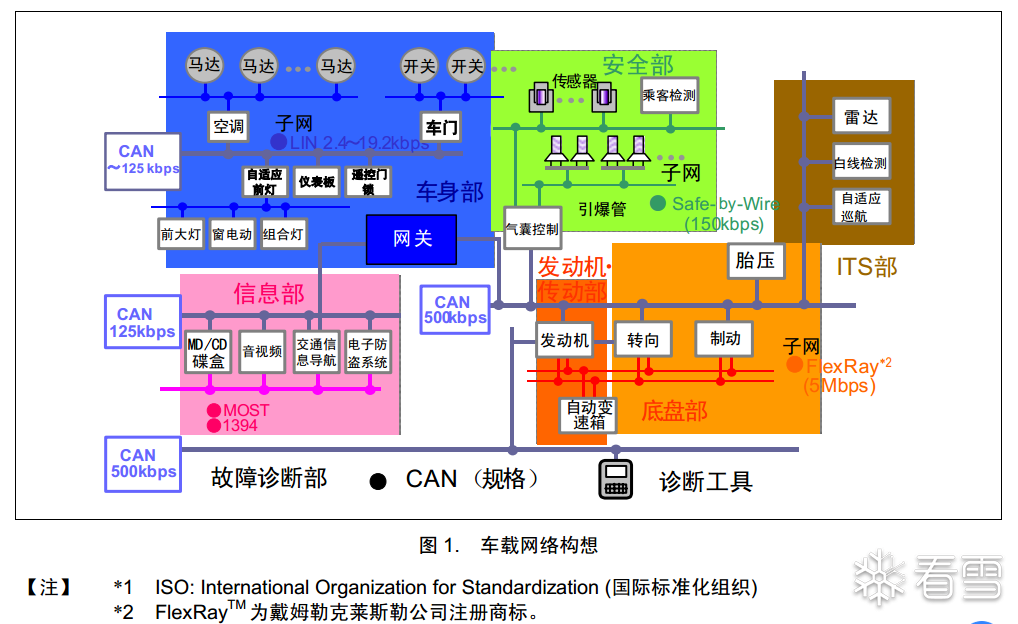
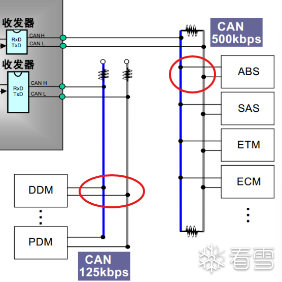
Transmission Rate
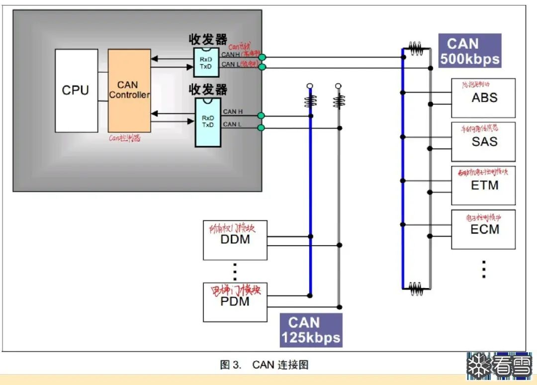
500kbps and 125kbps bus rates are used for different types of ECUs.
◆ 500kbps CAN bus connects ABS (Anti-lock Braking System), SAS (Steering Angle Sensor), ETM (Engine Electronic Control Module), and ECM (Electronic Control Module), typically used for control signals that require a higher transmission rate.
◆ 125kbps CAN interface connects DDM (Door Module) and PDM (Lift Door Module), typically used for control signals that require a lower transmission rate.
Differential Signal
Differential signal communication is a method of transmitting data over two wires (or signal lines), primarily used to improve anti-interference capability and signal integrity.
Concept
In differential signal communication, two versions of the same signal are transmitted simultaneously over two wires:
◆ Positive Signal (+): Original signal
◆ Negative Signal (-): Inverted version of the original signal
For example:
If the positive signal is high ( +5V), the negative signal is low (0V).
If the positive signal is low (0V), the negative signal is high (+5V).
Signal Generation
The sender generates a differential signal using a differential driver (or transmitter):
◆ Positive Signal Line (D+): Directly transmits the original signal
◆ Negative Signal Line (D-): Transmits the inverted original signal
For example:
When sending logic “1”, D+ line is high, and D- line is low.
When sending logic “0”, D+ line is low, and D- line is high.
Signal Transmission
Differential signals are transmitted simultaneously over two wires, and the voltage difference between the wires (i.e., differential voltage) determines the logical state of the signal:
Differential Voltage = D+ Voltage – D- Voltage
◆ Logic “1” typically appears as a positive differential voltage (e.g., +2V)
◆ Logic “0” typically appears as a negative differential voltage (e.g., -2V)
Signal Reception
The receiver uses a differential receiver to interpret the signal.
The differential receiver does not directly read the voltage values of D+ or D-, but instead<span>reads the voltage difference between them</span>:
◆ If the voltage of D+ is higher than that of D-, the receiver interprets it as logic “1”.
◆ If the voltage of D+ is lower than that of D-, the receiver interprets it as logic “0”.
Noise Immunity Principle
When external noise (such as electromagnetic interference) affects the transmission line, it usually affects both D+ and D- lines simultaneously, causing their voltages to rise or fall together.
However, since the receiver only cares about the voltage difference between the two lines, this common-mode noise does not change the logical state of the signal, thus it can be effectively suppressed.
Differential Signal Specifications in CAN Protocol
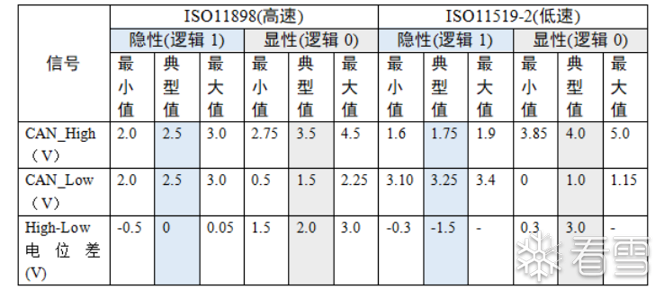
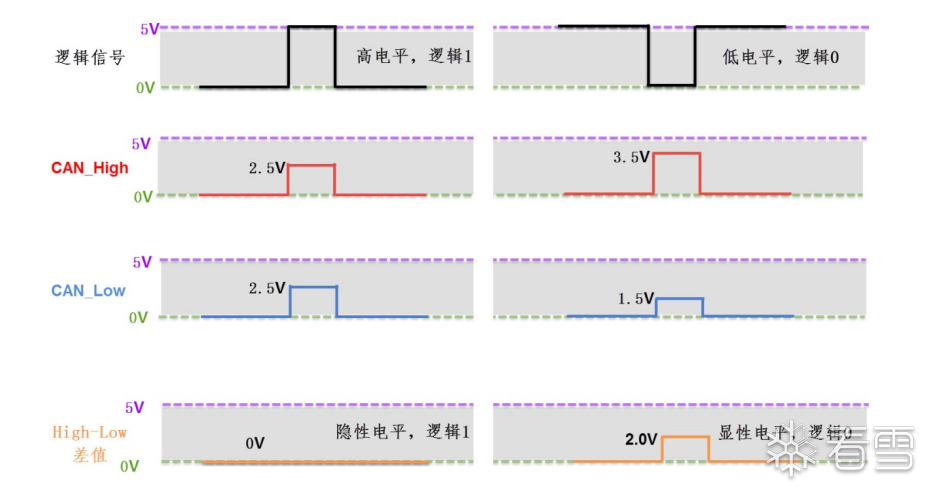
In the physical layer of the CAN bus protocol, there is only one pair of differential lines, which can only represent one signal at a time, thus for communication nodes, CAN communication is half-duplex, requiring time division for data transmission and reception.
In the CAN communication network, due to the shared bus, only one communication node can send signals at a time, while the others can only receive at that moment.
2. Bus Network
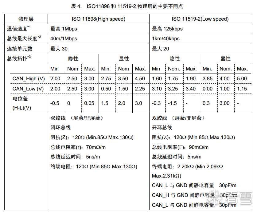
The physical layer of CAN has two forms
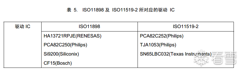
◆ High-speed, short-distance “closed-loop network” as per ISO11898 standard
◆ Low-speed, long-distance “open-loop network” as per ISO11519-2 standard
Closed-loop Network
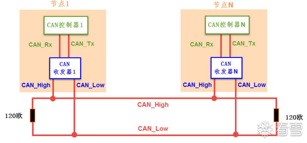
◆ Maximum bus length is 40m
◆ Maximum communication speed is 1Mbps
◆ Each end of the closed-loop bus has a 120Ω resistor
Open-loop Network
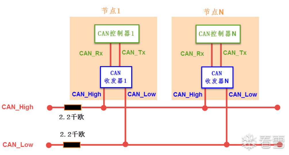
Maximum bus length is 1km
Maximum communication rate is 125kbps
Each bus is connected in series with a 2.2kΩ resistor
3. Communication Nodes
Composition of Communication Nodes
◆ A CAN controller and CAN transceiver constitute a communication node
◆ The controller is connected to the transceiver via CAN_Tx and CAN_Rx signal lines
◆ The transceiver is connected to the CAN bus via CAN_High and CAN_Low signal lines
◆ CAN_Tx and CAN_Rx use standard TTL-like logic signals
◆ CAN_High and CAN_Low are a pair of differential signal lines
Multiple Communication Nodes Connection
One bus can connect multiple nodes, the CAN communication protocol does not address code nodes, but encodes the data content. The number of nodes is theoretically unlimited (as long as the bus load is sufficient, it can be enhanced through repeaters).
Communication Process of Nodes
The receiving and sending processes are opposite.
Sending Data
◆ The controller sends the binary code to be sent through the CAN_Tx line to the transceiver.
◆ The transceiver converts this ordinary logic level signal into a differential signal.
◆ The differential signal is output to the CAN bus network through the differential lines CAN_High and CAN_Low.
Receiving Data
The CAN bus network sends data through the differential lines CAN_High and CAN_Low. The transceiver converts the received CAN_High and CAN_Low signals into ordinary logic level signals, and finally outputs them to the controller via the CAN_Rx line.
CAN Level Conversion Chip (Part)
Protocol Layer of CAN Protocol
1. Baud Rate and Bit Synchronization
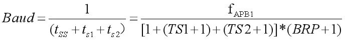
Communication Baud Rate
== As long as each communication node on the bus agrees on the time length of 1 Tq and how many Tq each data bit occupies, the CAN communication baud rate can be determined ==
SJW[1:0] Resynchronization Compensation Width
TS1[3:0] Time Segment 1
TS2[2:0] Time Segment 2
BRP[9:0] Baud Rate Prescaler
SS Synchronization Segment is always equal to 1
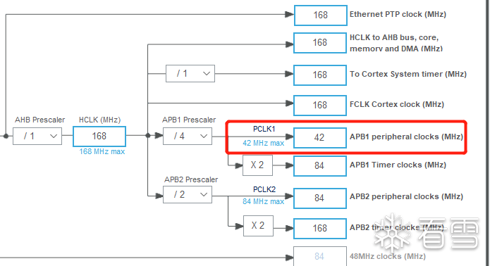
Set the clock frequency of APB1, STM32F1 is usually 36MHz (external 8M crystal oscillator)
For detailed calculation methods, refer to: Setting CAN Bus Baud Rate – Taking STM32F103 as an Example – Zhihu (zhihu.com)
Example:
Assuming 1Tq=1us, and each data bit consists of 19 Tq, the time to transmit one data bit is;
T1bit=19us, thus the number of data bits that can be transmitted per second is: 1×10^5/19 = 52631.6 (bps)
The number of data bits that can be transmitted per second is the baud rate in communication, CAN belongs to asynchronous communication, and there is no clock signal line. Each node connected to the same bus network communicates at the agreed baud rate, (simultaneously using the “bit synchronization” method to resist interference, absorb errors, and ensure correct sampling of bus level signals to ensure normal communication).
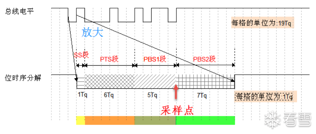
Bit Timing Decomposition
The CAN protocol decomposes the timing of each data bit into SS segment, PTS segment, PBS1 segment, PBS2 segment
The total length of the four segments equals the length of a CAN data bit.
The minimum time unit after decomposition is Tq (a complete bit consists of 8~25 Tq).
(Here, high and low levels directly represent signal logic 0 or logic 1)
Example data: bit length is 19Tq
◆ SS segment occupies 1Tq
◆ PTS segment occupies 6Tq
◆ PBS1 segment occupies 5Tq
◆ PBS2 segment occupies 7Tq
SS Segment
Synchronization segment (fixed size of 1Tq)
== If the signal change edge detected on the bus is within the range of the SS segment, it indicates that the node is synchronized with the bus timing ==
PTS Segment
Propagation Time Segment (size of 1~8Tq)
== Compensates for the physical delay time of the network ==, the total delay of the input comparator and output driver on the bus
PBS1 Segment (PHASE SEG1)
Phase Buffer Segment (size of 1~8Tq)
== Compensates for the edge phase error ==, its time length can be extended during resynchronization
PBS2 Segment (PHASE SEG2)
Another Phase Buffer Segment (size of 2~8Tq)
== Also used to compensate for edge phase error ==, the time length can be shortened during resynchronization
Synchronization Process Analysis
Briefly, synchronization allows the data receiver to correctly interpret and process the data received from the sender, ensuring that the receiver can accurately identify the start and end of each data bit.
CAN synchronization is divided into two types: hard synchronization and soft synchronization.
Hard Synchronization (for Short Frame Transmission)
Hard synchronization occurs when a CAN node detects a dominant edge (i.e., a transition from recessive bit to dominant bit) on the bus.
Transition from Recessive Bit to Dominant Bit:
◆ Dominant Bit: Represents logic “0”
◆ Recessive Bit: Represents logic “1”
◆ Edge: An edge refers to the transition of a signal from one state to another. For example, the transition from a recessive bit (logic 1) to a dominant bit (logic 0) is called a “dominant edge”.
Working Principle:
◆ Frame Start Bit (SOF):
◆ Trigger Hard Synchronization:
Example:
Assuming there are two CAN nodes, Node A (sender) and Node B (receiver) (communicating on the same CAN bus).
Node A prepares to send a data frame, while Node B is responsible for receiving that frame.
1. The bus is in an idle state
Before communication begins, the CAN bus is in an idle state, with the bus voltage at a recessive bit (logic 1), and both Node A and Node B are waiting for changes on the bus.
1. Node A sends the data frame start bit (SOF)
Node A begins to send a data frame. The rules of CAN communication state that the start of a frame is indicated by a dominant bit, called the Frame Start Bit (SOF). Therefore, Node A switches from a recessive bit (logic 1) to a dominant bit (logic 0), causing a voltage change that increases the difference between the CAN H and CAN L lines.
1. Node B detects the dominant edge and performs hard synchronization
When Node B detects this voltage change (dominant edge) on the bus, it performs a “hard synchronization” operation:
◆ Node B’s internal bit clock will be immediately reset and start a new timing cycle.
◆ This timing cycle aligns with the cycle of data transmission from Node A, ensuring that Node B can synchronize with Node A to read the subsequent data bits.
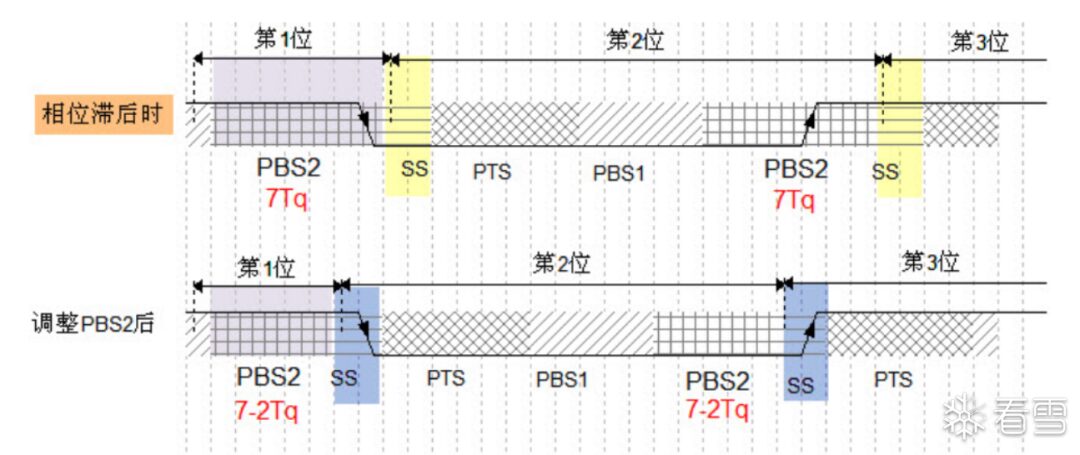
Resynchronization (for Long Frame Transmission)
During long frame transmission, (clock drift leads to a deviation between the node’s clock and the bus’s clock) ensuring synchronization of the node’s clock with the bus.
Basic Principle:
The internal clock (bit clock) of the CAN node has shifted relative to the signal on the bus,
Resynchronization aligns the clock by detecting == the transition edges of ordinary data bits (from high to low, or from low to high) ==.
Phase Ahead (Clock Fast):
The node’s clock is faster than the bus clock, meaning the node detects the data bit transition edge earlier than the bus.
== The time of phase buffer segment 1 (PBS1) is extended to align the node’s clock with the bus. ==
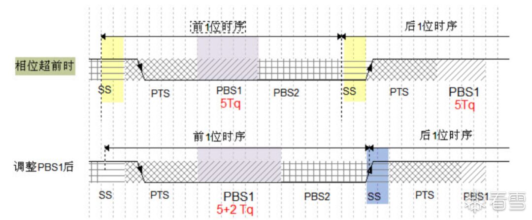
Phase Lag (Clock Slow):
The node’s clock is slower than the bus clock, and the node detects the signal after the bus transition edge.
== The time of phase buffer segment 1 (PBS1) is reduced to catch up with the bus clock. ==
Resynchronization Compensation Width (SJW)
A mechanism to adjust the clock to correct deviations between the node’s clock and the bus signal.
Maximum SJW Limit
The CAN controller typically sets a maximum value for SJW (the adjustment range of the clock during a single synchronization operation cannot exceed the set maximum value).
If the deviation exceeds the maximum value (cannot be completed in one go), it can only be completed through multiple small adjustments.
Adjustments of PBS1 and PBS2
◆ PBS1 (Phase Buffer Segment 1):
◆ PBS2 (Phase Buffer Segment 2):
2. Message Types and Structure
SPI communication, chip select, clock signal, data input, and data output all have separate signal lines.
I2C protocol includes two signal lines for clock and data signals, while asynchronous serial communication includes two signal lines for receiving and sending.
However, CAN only has two differential signal lines (which can only express one signal), so the CAN protocol == packages data, operation commands (such as read/write), and synchronization signals, and the packaged content is called a message.
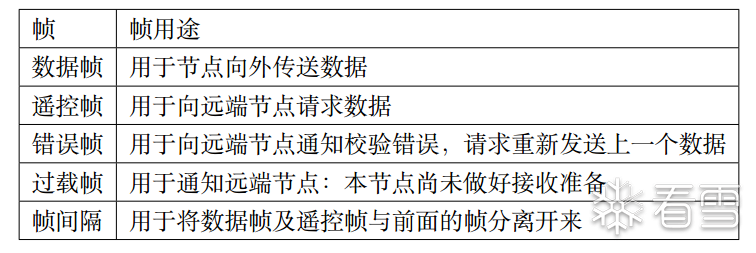
Message Types
Transmission Start Tag + Chip Select (Identification) Tag + Control Tag + Raw Data Segment + CRC Check Tag + Acknowledge Tag + Transmission End Tag
The above content is packaged in a specific format, allowing a single channel to express various signals, and the corresponding device can decode it according to the format to restore the data – CAN data frame.
Data Frame Structure
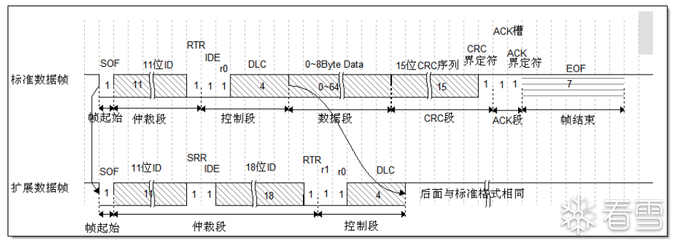
Start: (Frame Start)
A dominant bit (logic 0)
Middle:
Arbitration segment, control segment, data segment, CRC segment, ACK segment
End: (Frame End)
7 consecutive recessive bits (logic 1)
Arbitration Segment
== When multiple messages are sent, the arbitration segment determines the specific transmission message ==
Arbitration Principle:
◆ Physical protocol basis: When both dominant and recessive levels appear on the bus, the state of the bus will be set to dominant level.
◆ == If two nodes compete for control of the CAN bus simultaneously, when they send messages, if a recessive level appears first, it will lose control of the bus and enter receiving state ==
◆ Example:
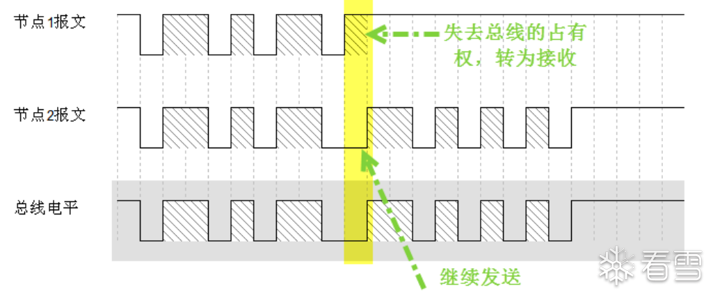
In the starting phase, the voltage sent by both devices is the same, so they continue to send data.
At the arrow timing, Node Unit 1 sends a recessive level, while Node Unit 2 sends a dominant level, causing the physical protocol basis of the bus to express the dominant level of Unit 2, allowing that message to continue transmission.
Arbitration Segment ID Data Bit (Identifier):
◆ Includes standard format (11 bits) and extended format (29 bits)
◆ Determines the priority of data frame transmission (<span>the priority of the CAN protocol is not determined by node address allocation, but by the ID of the data being sent</span>)
◆ Determines whether a node receives this data frame
Arbitration Segment RTR, IDE, SRR Data Bits
◆<span>IDE Bit</span> (Identifier Extension Bit): Distinguishes between standard format and extended format, == dominant level indicates standard format, recessive level indicates extended format ==
◆<span>RTR Bit</span> (Remote Transmission Request Bit in standard format): Distinguishes between data frames and remote frames, == dominant level indicates data frame, recessive level indicates remote frame ==
◆<span>SRR Bit</span> (Remote Transmission Request Bit in extended format): In extended frames, the SRR bit is recessive in data frames, while RTR is dominant in data frames, therefore, among two ID messages with the same standard format and extended format, the standard format has a higher priority.
Control Segment
Specifies the length of the message and the use of extended identifiers
◆<span>IDE</span> Bit (Identifier Extension Bit): Distinguishes between standard frames and extended frames, dominant level indicates standard format, recessive level indicates extended format
◆<span>RTR</span> Bit (Remote Request Bit): Distinguishes between data frames and remote frames, dominant level indicates sending data frame, recessive level indicates sending remote frame (which does not contain data, usually used to request other nodes to send data)
◆<span>Reserved Bit</span> (r0, r1): Used for protocol extension, generally set to dominant level
◆<span>DLC Bit</span> (Data Length Code): Indicates the number of actual data bytes transmitted in the message (4-bit field), ranging from 0-8, corresponding to the byte size of the data (the reserved 4 bits ensure protocol extensibility).
Data Segment
◆ Contains the raw data information (0-8 bytes)
◆ Follows the MSB principle: Most Significant Bit first transmission principle (MSB is generally Ethernet protocol, CAN protocol; conversely, LSB principle is generally for files and image encoding formats).
CRC Segment
Ensures data integrity, contains CRC sequence and CRC delimiter
CRC Sequence
◆ Size is 15 binary bits
◆ Calculated by the sending node based on its transmitted message content (arbitration segment, control segment, data segment, etc.)
◆ Calculated using a predefined CRC polynomial on the message’s bit stream
◆ After receiving the message, the receiver performs the same CRC calculation and compares its calculated CRC value with the received CRC sequence.
CRC Delimiter
Length fixed at 1 recessive bit, used to separate CRC sequence from the subsequent ACK segment
ACK Segment
Ensures the data frame is correctly received, contains ACK slot and ACK delimiter
ACK Slot
Used by the receiving node to confirm whether the message has been correctly received; if the message is correctly received and without error, the receiving node sends a confirmation signal to the sending node through the ACK slot (overwriting the recessive bit with a dominant bit).
Working Principle:
◆ The sending node only sends recessive bits in the ACK slot (1):
◆ The receiving node is responsible for overwriting the recessive bit in the ACK slot:
ACK Delimiter
Length fixed at 1 recessive bit, separates the ACK slot from the end frame.
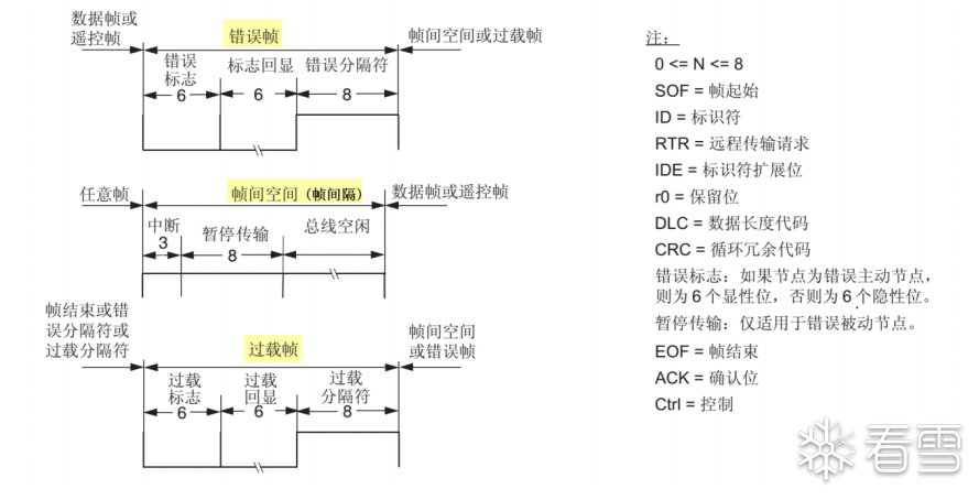
3. Other Message Formats (Similar Structure)
STM32F407 CAN Controller Analysis
Basic Structure
Official Document:
https://www.ti.com/lit/an/sloa101b/sloa101b.pdf
Basic Support:
Supports bxCAN controller (CAN protocol 2.0A and 2.0B standard, maximum speed 1Mb/s)
Supports automatic reception and transmission of CAN messages
Supports messages using standard ID and extended ID
Supports software-controlled sending message priorities
Supports recording sending time, 2 FIFO queues with a depth of 3 (two FIFO queues, each can store up to 3 data items), does not support DMA (Direct Memory Access, a technique for efficient data transfer without CPU intervention).
Framework Diagram:
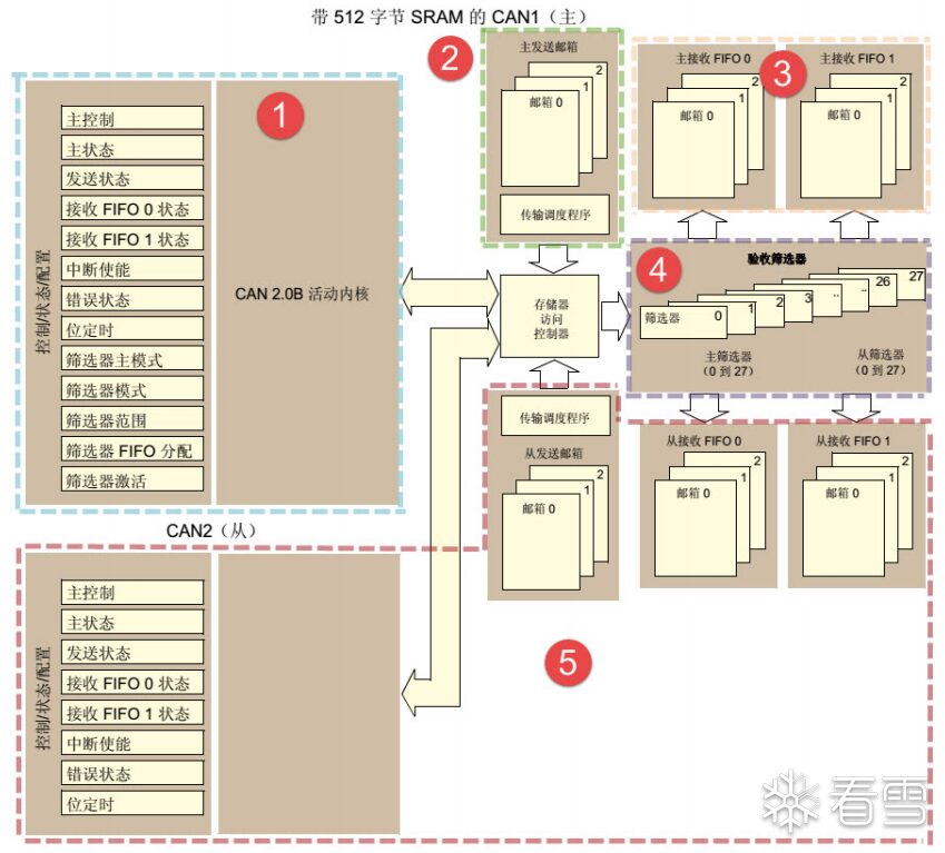
CAN Controller 1 and 2
CAN1 is the master device (controls memory access controller)
CAN2 cannot directly access the storage area (must support CAN1 peripheral clock)
Component Analysis
CAN Control Core
Includes the CAN control core (mainly analyzes the main control register CAN_MCR and timing register CAN_BTR)
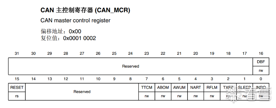
CAN_MCR (Main Control Register)
Mainly controls the operating mode of CAN.
Register Control Diagram
DBF Debug Freeze Function
Used to set the communication function of the CAN controller when entering debug mode, working state and prohibiting send/receive state.
== Setting to prohibit send/receive state will close communication functionality after entering debug state == (does not hinder FIFO access, while allowing reading of already received messages).
TTCM Time Triggered Mode
Used to support sending and receiving messages at scheduled time points (used in scenarios requiring strict time synchronization and real-time performance).
Function Implementation: (Internal timer generates timing)
◆ Start TCM mode, the internal timer of CAN accumulates with each CAN bit time.
◆ The start bit of the frame sent or received is sampled, and the controller generates a timer.
◆ The generated timer is saved in CAN_RDT_xR (Receive Timer) and CAN_TDTxR (Send Timer), to indicate the time of message sending and receiving.
ABOM Automatic Offline Management
Used to handle situations where CAN nodes enter offline state due to excessive error accumulation.
Protocol Basis:
When a CAN node in offline detects that the cumulative sending or receiving errors exceed a certain threshold, it automatically enters Bus-Off (offline) state, in this state, the node cannot receive or send any CAN messages.
Function Implementation:
◆ Error monitoring and offline state
◆ Automatic recovery mechanism:
◆ Manual recovery mechanism
When the ABOM function is not enabled, after entering the offline state, manual recovery is needed (for example: external program sends reset command, restart CAN node).
AWUM Automatic Wakeup Mode
Automatically listens for sleep activity after the CAN controller enters low-power sleep mode and automatically wakes up the device when communication occurs.
Function Implementation:
◆ Sleep Mode: Can enter sleep mode when there is no communication demand to reduce power consumption.
◆ Automatic Wakeup: When data transmission occurs on the CAN wakeup line, AWUM will wake up the automatic controller, restoring it from sleep mode to normal working state and starting to handle communication.
NART Automatic Retransmission Function
◆ When the NART bit is set to 0, the CAN controller == automatically retransmits the message when sending fails, until it successfully sends the status.
◆ When the NART bit is set to 1, the automatic retransmission function is disabled, and regardless of the sending result, each message will only be sent once.
RFLM Receive FIFO Lock Mode
Used to lock the receive FIFO.
◆ When FIFO is locked, if the received FIFO overflows, the next message will be discarded, keeping the current message in FIFO.
◆ When FIFO is not locked, the next received message will overwrite the oldest message in FIFO.
TXFP Message Sending Priority Determination Method
TXFP controls which message to send first when there are multiple messages waiting to be sent in the CAN sending mailbox.
◆ When TXFP is set, the order of sending messages is based on the order of entry (i.e., first in first out, “FIFO principle”).
◆ When TXFP is not set, messages are sent based on the priority of message IDs, with lower ID values having higher priority.
CAN_BTR (Bit Timing Register) and Baud Rate
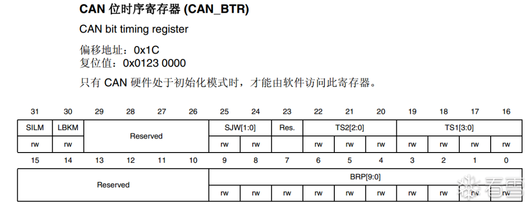
Configures test mode, baud rate, and various segment parameters.
CAN_BTR Modes
Silent and Loopback modes are used for debugging and testing CAN communication (activated by bits 30 and 31 in the CAN_MCR register, as shown above).
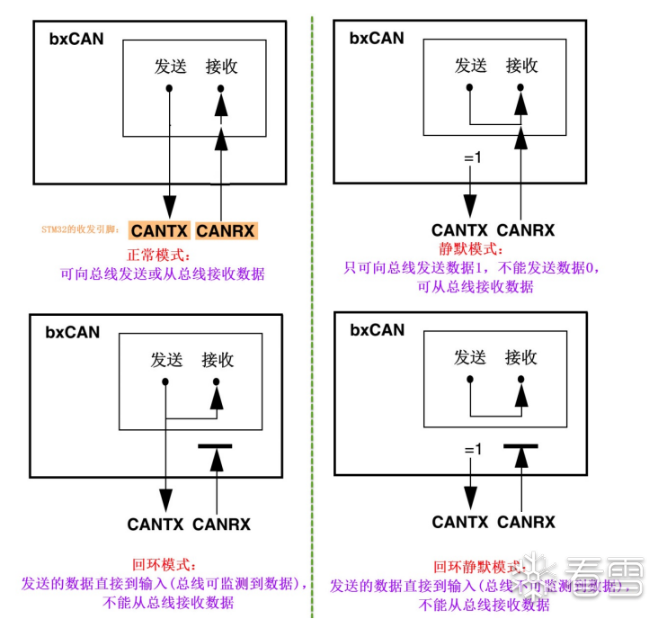
SILM Silent Mode (Debug)
CAN can receive data but will not actively send data, performing interference (if an error is detected, it will not send an error frame).
Mainly used for sleep listening, without affecting normal communication in sleep mode.
<span>Bit 31</span>
0: Normal operation
1: Silent mode
LBKM Loopback Mode (Debug)
CAN directly sends its own messages back to its own registers for self-testing (nodes can self-test whether messages can be returned normally without connecting to the CAN network).
<span>Bit 30</span>
0: Disable loopback mode
1: Enable loopback mode
Combined Mode
If both Silent Mode (SILM = 1) and Loopback Mode (LBKM = 1) are enabled, the CAN controller will enter Silent Loopback Mode.
The CAN controller will not communicate with actual traffic, but can achieve automated self-receiving through internal self-loopback.
STM32 Peripheral Bit Timing:
Sync Segment SYNC_SEG + Bit Segment BS1 + Bit Segment BS2
(Sampling point is located at the junction of BS1 and BS2 segments)
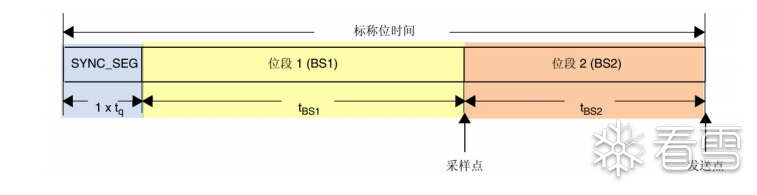
◆ SYNC_SEG segment is fixed at 1Tq
◆ The lengths of BS1 and BS2 are set in CAN_BTR (supporting length growth or shortening during resynchronization).
BS1 segment is similar to PTS segment + PBS segment in the CAN standard protocol.
BS2 segment is similar to PBS2 segment in the CAN standard protocol.
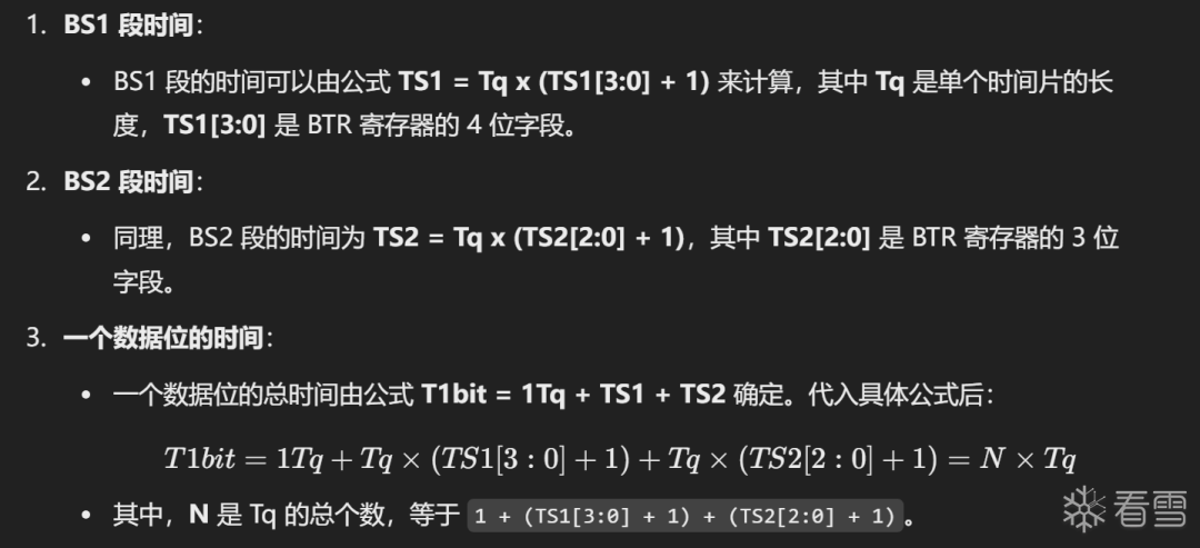
Baud Rate Configuration
Configures the bit timing register CAN_BTR’s TS1[3:0], TS2[2:0], sets the lengths of BS1 and BS2 segments, and determines the time of each CAN data bit:
BS1 Segment Time: TS1=Tq x (TS1[3:0] + 1)

BS2 Segment Time: TS2= Tq x (TS2[2:0] + 1)

Time of a Data Bit: T1bit =1Tq+TS1+TS2=1+ (TS1[3:0] + 1)+ (TS2[2:0] + 1)= N Tq
Calculation Formula
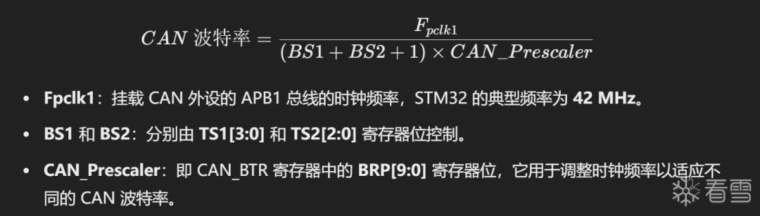
Fpclk is generally 42MHz:
CAN Sending Mailbox
CAN has three sending mailboxes (can support up to 3 pending messages).
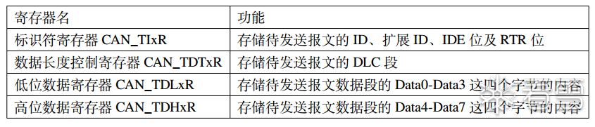
Mailbox Composition
CAN_TIxR (Identifier Register) + CAN_TDTxR (Data Length Control Register) + CAN_TDLxR, CAN_TDHxR (2 Data Registers)
Detailed Identifier Explanation
Standard Identifier (11 bits) and Extended Identifier (29 bits)
When sending a message, the data needs to be written to the identifier register CAN_TIxR according to the identifier type for transmission.
Standard Identifier (11 bits)
STDID[10:0] register bits store the 11-bit value of the Standard Identifier.
The ID in the message is the content of STDID, all bits can be directly used for message priority judgment and matching.
Extended Identifier (29 bits)
STDID[10:0] and EXTID[17:0] together store the Extended Identifier.
◆ The upper 11 bits are stored in STDID[10:0] (corresponding to bits [18:28] of the extended identifier).
◆ The lower 18 bits are stored in EXTID[17:0] (corresponding to bits [0:17] of the extended identifier).
The 29-bit identifier jointly determines the message priority and target address.
Send Request
The TMIDxR_TXRQ (set to 1 to start transmitting data) in the CAN_TIxR register is used for sending requests:
1. Determine the identifier (extended or standard)
2. Write the identifier into the standard STDID[10:0] & extended identifier EXTID[17:0].
3. Configure other message segments like data fields.
4. Set TMIDxR_TXRQ to 1 to request sending the message.
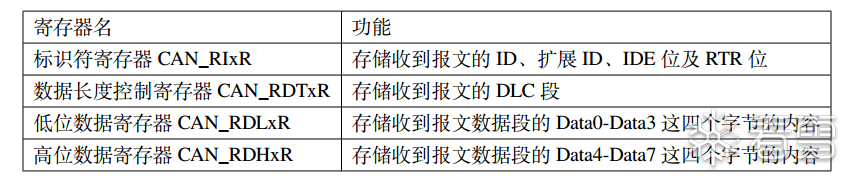
CAN Receive FIFO
The receive FIFO is specifically used to store received CAN messages.
Each CAN peripheral has 2 receive FIFOs (FIFO0 and FIFO1), each FIFO contains 3 mailboxes → a CAN interface can cache a maximum of 6 received messages.
Working Mechanism
◆ Message Storage: After receiving a message, it is stored in FIFO, and the counter increments.
◆ Reading Message: When the CPU reads the message, the counter decrements.
◆ Status Monitoring: The current status of FIFO can be obtained through the status register (message count, overflow error).
◆ Lock Mode (RFLM)
-
Lock Mode: In case of FIFO overflow, the new message will be discarded, retaining the current message in FIFO.
-
Non-Lock Mode: In case of FIFO overflow, the new message will overwrite the oldest message in FIFO.
Acceptance Filter
== Used to filter received CAN messages ==
The CAN bus is broadcast; all nodes receive all messages, but filtering can selectively receive specific messages.
Structure and Configuration
CAN1 and CAN2 share 28 filter groups.
Each filter group has 2 registers.
(Different working modes and masks can be configured to filter different messages.)
Filter ID Length
The length of the filtered message ID determines the working mode in two different length modes:
31-bit Mode:
◆ Checks the Standard Identifier (STDID) of 11 bits (STDID[10:0]).
◆ The Extended Identifier (EXTID) of 18 bits (EXTID[17:0]).
◆ IDE (Identifier Extension Bit)
◆ RTR (Remote Transmission Request Bit)
16-bit Mode:
◆ Checks the Standard Identifier (STDID) of 11 bits (STDID[10:0]).
◆ RTR Bit
◆ IDE Bit
◆ The 3 bits of the Extended Identifier (EXTID) (EXTID[17:15]).
Configure CAN_FS1R (Filter Scale Register) bits FSCx to select whether the filter uses 31-bit mode or 16-bit mode.
Working Modes
Two filtering modes:
1. Identifier List Mode: (similar to a whitelist)
2. Mask Mode: (similar to keyword matching)
Configure CAN_FM1R (Filter Mode Register) bits FBMx to select the filter’s working mode (list mode or mask mode).
Four State Combinations
1. 31-bit Mask Mode
2. 31-bit Identifier List Mode
3. 16-bit Mask Mode
4. 16-bit Identifier List Mode

Look Snow ID: gir@ffe
https://bbs.kanxue.com/user-home-989049.htm

Share the Ball

Like the Ball

Watching the Ball