01 UART Outputting Analog Signals
1. Introduction
Yesterday, someone commented on the “Serial Music” VLOG, raising a very good question. That is, what are the advantages of using the microcontroller’s UART output signal low-pass filtered to obtain an analog signal compared to using traditional PWM output signal low-pass filtered to obtain an analog signal? In response, someone answered that at least in common computer interfaces, the UART interface is more prevalent, while PWM interfaces are hard to find. In addition to this viewpoint, let’s look at the differences between UART and PWM outputting analog signals through practical comparison.

AD\Test\2024\PWM
2. Testing Method
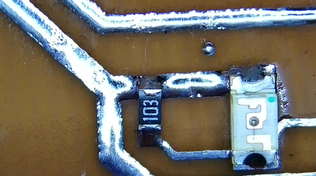
Next, let’s design the testing circuit, still using yesterday’s STM32 microcontroller. The interface has been simplified, leading out the output port of UART2, and also leading out the two PWM channels of TIMER4, and finally adding an IO port for the oscilloscope synchronization signal. A single-sided PCB was manually laid out. Ultimately, there were two flying wires, and during soldering, a 0-ohm resistor was used for short-circuiting.
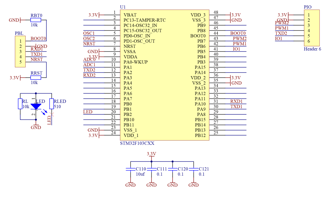
▲ Figure 1.2.1 Schematic Diagram of Testing Circuit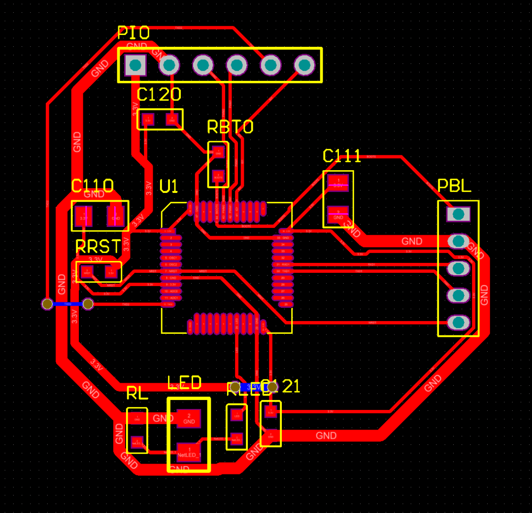
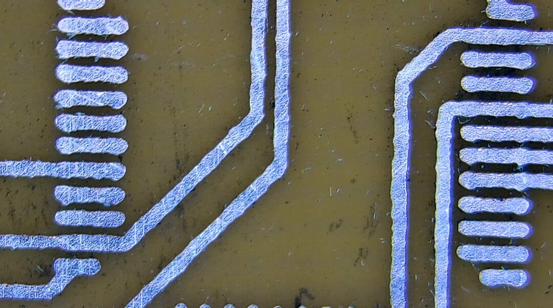
▲ Figure 1.2.2 PCB Layout of Testing CircuitUsing a one-minute board-making method, the testing circuit board was produced. In fact, it was made twice. The first time, due to not diluting the etching liquid, the lines were over-etched. The second time, water was added to the etching liquid, slowing down the etching speed, resulting in very perfect lines. Next, soldering the test.
Soldering the circuit board. Cleaning it can be seen that some areas have not been cleaned properly. Later, ultrasonic cleaning was performed again.
3. Test Results
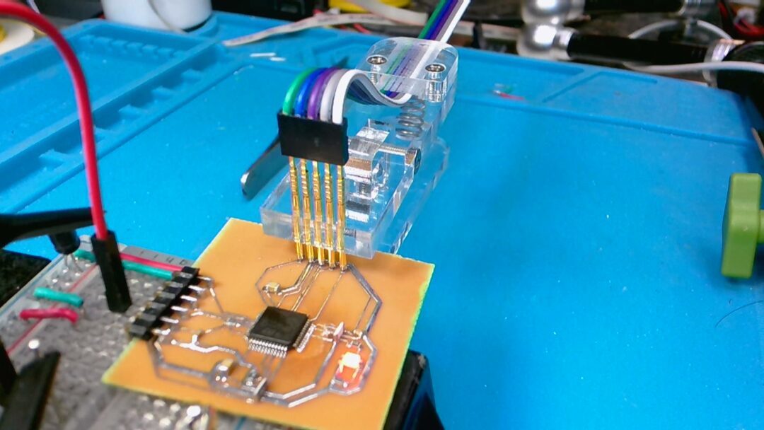
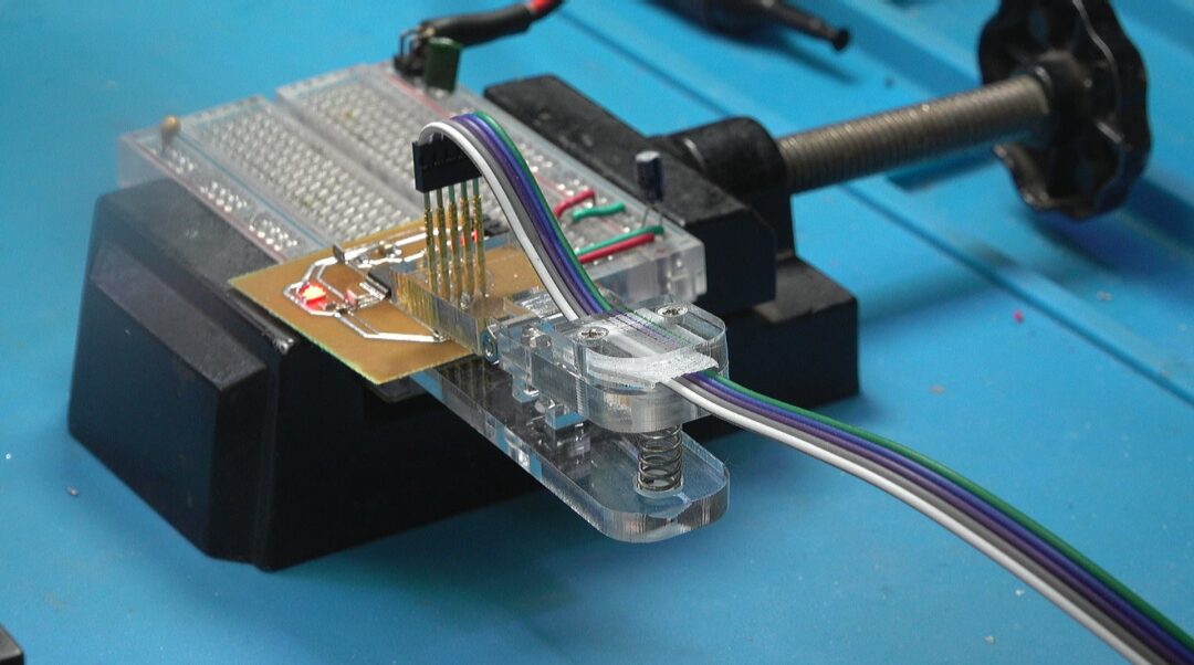
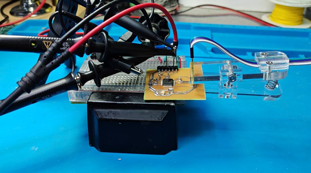
A testing circuit was built on a breadboard. The microcontroller operating voltage of 3.3V was provided. The testing software was downloaded through probe clips.
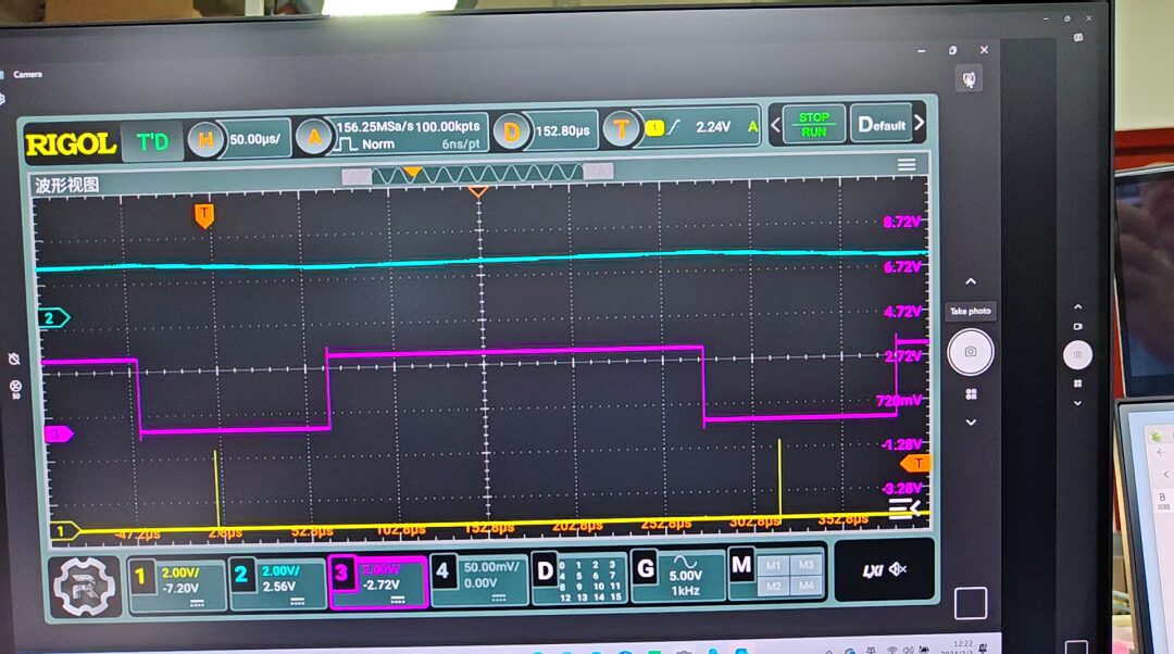
▲ Figure 1.3.1 UART Output SignalUsing an oscilloscope to observe the output signal of UART2. The cyan signal above is the TXD2 signal, and the yellow one is the DMA interrupt signal output from the circuit’s IO port. There are 32 sending bytes between the two interrupt signals. The data being sent is 0x0, and the pulses seen are the stop bits in serial communication. Out of the 32 bytes, a total of 256 bits can be set.
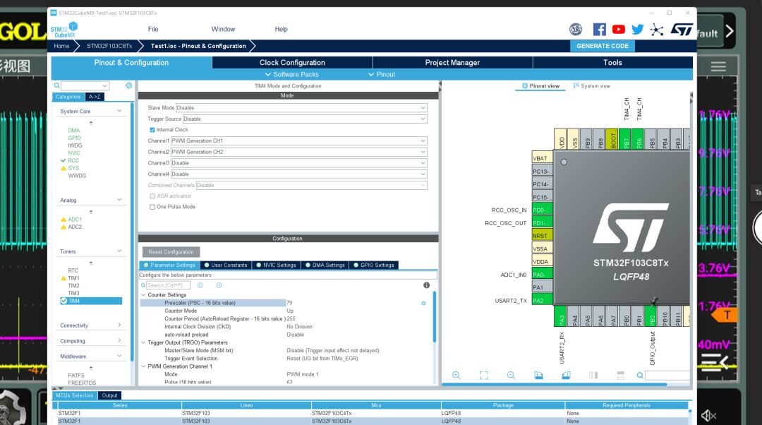
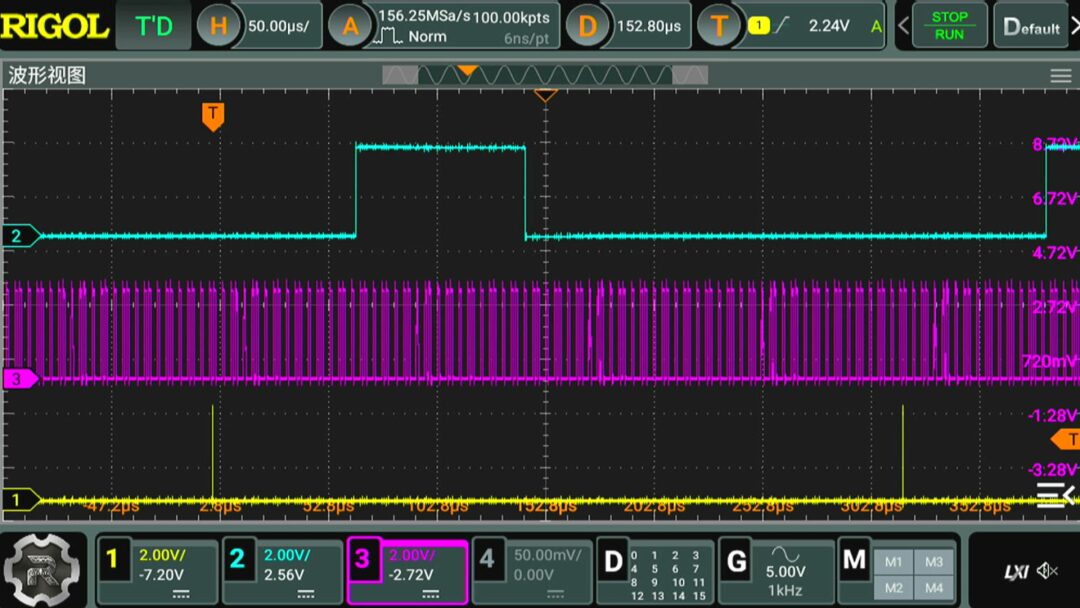
Now, 25% of the 256 controllable bits are set to high level. These bits set to high are uniformly distributed among the 256 bits. For comparison, setting the microcontroller’s TIMER4 outputs PWM waveforms, with its prescaler parameter set to 79, thus forming a PWM signal with the same period as the UART output’s 32 bytes. The PWM precision is also 256 levels. In the oscilloscope, the purple signal is the PWM waveform, with a duty cycle of 25%, and above it is the PWM waveform with a duty cycle of 25% output from UART. From this, we know that the signal output by UART actually belongs to PDM, which is Pulse Density Modulation signal. The actual modulation frequency is 1MHz, which is the baud rate set for the serial port.
▲ Figure 1.3.2 Output Duty Cycle 25% Corresponding Output Waveform
▲ Figure 1.3.3 PWM and UART Both Output 25% Duty Cycle Waveform4. Signal Comparison
Next, two measurements will be made. One is to measure the DC voltage in the UART and PWM output signals, and the other is to measure the magnitude of the AC component in the signal after RC low-pass filtering. First, measure the DC component corresponding to UART under different duty cycle settings, using the DC range of the digital multimeter DM3068 to measure the output signal, controlling the proportion of high levels in the UART output signal through the serial port, ranging from 0 to 100%. The output voltage DC component shows a perfect linear relationship with the duty cycle. Due to the presence of start and stop bits, the output voltage does not start increasing from 0V, and the maximum value is also lower than the high-level signal. Next, measure the DC component of the PWM signal. The measurement results show that the output voltage is proportional to the duty cycle. Comparing the DC components in the UART and PWM signals, it can be seen that the range of the DC signal output by UART is about 20% smaller than that of PWM.
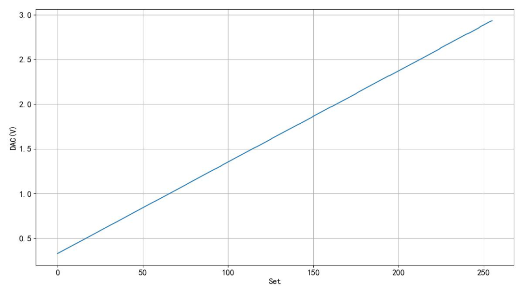
▲ Figure 1.4.1 UART Output Voltage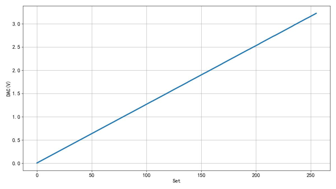
▲ Figure 1.4.2 PWM Output Voltage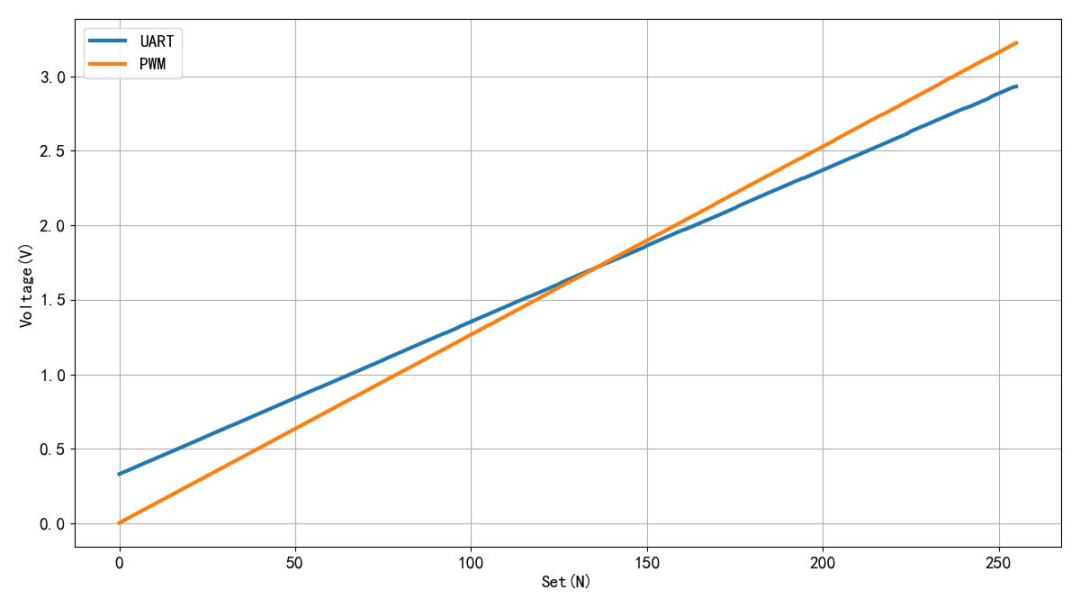
▲ Figure 1.4.3 Comparison of UART and PWM Output VoltagesUsing an RC low-pass filter to filter the UART output signal, with a resistor of 10k ohms and a capacitor of 0.1 microfarads. The effective value of the AC signal in the output signal was measured using the AC range of DM3068. The effective value of the AC signal was recorded under different duty cycles. From the observed waveform, the output signal is very stable. The measurement results also show that the AC component in the output signal tends to increase overall with the duty cycle. The maximum is around 4mV. Next, measure the AC component existing in the PWM signal after filtering with the same RC low-pass filter. It can be observed that there are fluctuations in the output filtered signal, and the measurement results show that when the duty cycle is 50%, the AC component reaches its maximum, exceeding 84mV. Comparing the AC components in the serial signal and the PWM signal, we can see the advantage of the serial output signal, which is that after RC low-pass filtering, the signal fluctuations are very small, only about 1/20 of a typical PWM waveform.
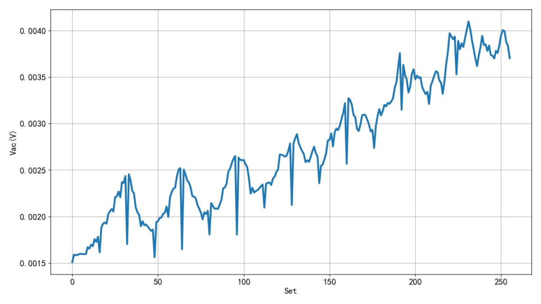
▲ Figure 1.4.4 AC Component in UART Output Signal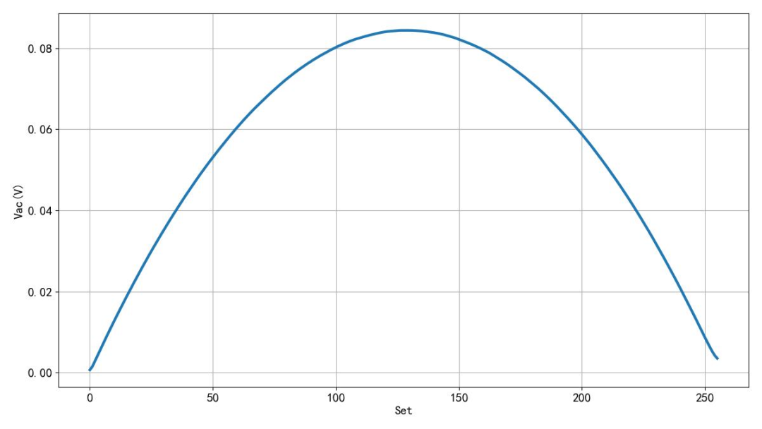
▲ Figure 1.4.5 AC Component in PWM Output Signal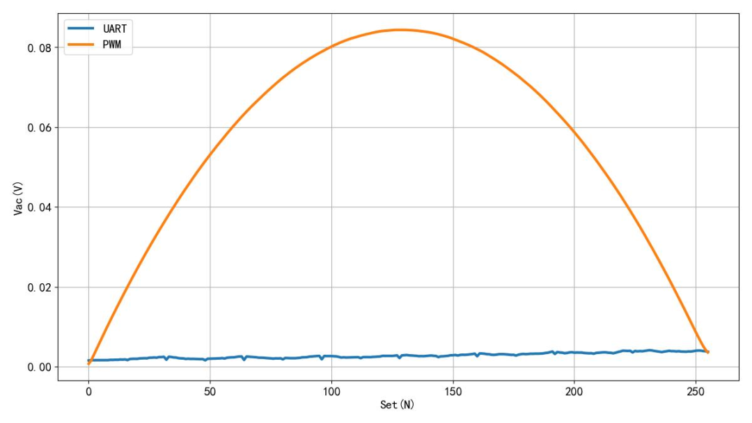
▲ Figure 1.4.6 Comparison of AC Components in UART and PWM Output Signals※ Conclusion ※
This article compares the characteristics of the microcontroller outputting DC quantities through the serial port and PWM port. Due to the presence of fixed start and stop bits, the range of the DC component of the serial output signal can only reach 80% of the operating voltage range. However, the DC component of the PWM output signal can reach the operating voltage range. But the AC component in the serial output signal, under the same RC low-pass filtering conditions, is 20 times smaller than that of the PWM output signal. This may be an advantage of the serial output analog quantity. Of course, this advantage is also due to its lower output bit count. For example, in the experiment, the serial output analog quantity is only equivalent to an 8-bit DAC. Today’s results are obtained through experimental measurement, and theoretical analysis can be used for next semester’s experiments in the Signals and Systems course.