Are you looking for more information about RS-485? Based on feedback from the TI E2E™ community, we have compiled a list of the most common questions regarding the design challenges of isolated RS-485 transceivers. We hope this list provides you with useful insights into RS-485 isolated signals and power.
1. When Is It Necessary to Isolate the RS-485 Bus?
Isolation prevents direct current (DC) and abnormal alternating current (AC) between two parts of a system while still supporting signal and power transmission between them. Isolation can generally prevent electrical components or personnel from being subjected to dangerous voltage and current surges; isolation used for personnel protection is called reinforced isolation. Isolation also prevents ground loops from forming during long-distance communication between nodes. Additionally, it allows for a much higher rate of change in ground potential difference between nodes than is recommended by the RS-485 standard.
2. How Many Nodes Can Be Connected to One RS-485 Bus?
To estimate the possible maximum bus load, RS-485 defines a hypothetical term called “unit load (UL)”, which represents a load impedance of approximately 12kΩ. The TIA/EIA RS-485 standard mandates that a maximum of 32 UL loads can be added to a single RS-485 bus. We calculate the UL of a node by using the input voltage divided by the leakage current in the worst-case performance ratio, as shown in Equation 1.
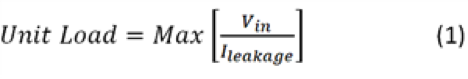
Once the UL of the node is calculated, the maximum number of nodes can be computed using Equation 2:
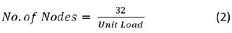
The single UL for most TI isolated RS-485 transceivers is 1/8, so the result is that a maximum of 256 nodes can be connected to an RS-485 bus.
3. What Is the Relationship Between Speed and Length for Isolated RS-485?
There is an inverse relationship between signal rate (speed) and cable length. The exact relationship depends on the resistance and capacitance of the cable itself. When building an RS-485 network, selecting the right cable is as important as choosing the transceiver to ensure reliable communication over the required distance. Figure 1 shows the correlation between signal rate and cable length. Circle 3 in the figure indicates the maximum cable length that is independent of the signal rate; in this region of the curve, the DC resistance of the cable causes signal attenuation, limiting the maximum communication distance. Circle 2 shows the inverse relationship between signal rate and cable length, which is caused by transmission line losses—the longer the cable, the greater the loss. Circle 1 allows you to ignore transmission line losses; the rise and fall times of the driver are the main limiting factors for maximum data transfer rate. The RS-485 standard recommends a maximum signal rate of 10Mbps; however, with today’s technology, signal rates have reached 50Mbps.
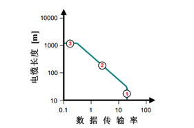
Figure 1: Relationship Between Signal Rate and Cable Length
4. What Is Fail-Safe Biasing, and How Is It Designed?
To comply with the RS-485 standard, when the differential input (VID) exceeds 200mV, the receiver output must generate a logic high level, and when VID is below -200mV, it must output a logic low level. However, invalid outputs can occur in the following three scenarios:
|
1 |
Bus open, such as a broken cable or disconnected connector. |
|
2 |
Bus short, such as damaged cable insulation causing a short circuit in the twisted pair. |
|
3 |
Bus idle, which occurs when there are no active drivers on the bus. |
In any of the above cases, for a terminated transmission line, the RS-485 receiver VID is zero, and the fail-safe output of the receiver is indeterminate.
Fail-safe biasing provides a differential voltage to the idle bus, allowing the receiver to maintain a logic high state. If fail-safe biasing is not considered, the termination resistor could pull the bus voltage down to 0V, causing erroneous outputs or signal oscillations. You can design fail-safe biasing by combining a resistor network with the RS-485 receiver. TI’s isolated RS-485 transceivers have integrated fail-safe biasing for open, shorted, or idle bus conditions, eliminating the need to build external circuits for fail-safe biasing.
5. When Should the RS-485 Bus Be Terminated, and What Are the Pros and Cons for the System?
In most RS-485 applications, termination resistors are matched to the characteristic impedance of the cable to prevent signal reflections. Termination resistors should be installed at both ends of the RS-485 bus. Some short-distance communications may operate without termination resistors, but termination is the best practice for all applications. The downside of termination resistors is the DC loss generated by the resistors, which can increase power consumption in the system. Despite this drawback, termination resistors are still a good choice for the vast majority of applications.
6. What Type of Transient Protection Is Required for Isolated RS-485 Devices?
The type of transient protection used for isolated RS-485 devices depends on the types of interference that may occur in the final system, such as electrostatic discharge (ESD), electrical fast transients (EFT), or surges, as well as the required level of protection. TI’s isolated RS-485 transceiver product line, if it has a floating isolated ground conductor, will have some degree of internal transient protection integrated into the transceiver bus termination. Furthermore, with proper system design, you can utilize the isolation barrier to form a high impedance against these transient changes. If you wish to avoid differential transients in the system and have tested all transients related to grounding of the final device, connecting a protective earth (PE) to the logic side of the isolated transceiver will ensure that all high-voltage transients occur at the isolation barrier. Connecting PE to the logic side can eliminate the need for external components like transient voltage suppression (TVS) diodes or surge resistors.
Figure 2 shows enhanced transient protection technology using ISO1410.
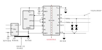
Figure 2: Half-Duplex Isolated RS-485 Transceiver,
with Optional Bus Protection Components
7. How Do You Construct an Isolated Power Supply for Isolated RS-485 Nodes?
There are several options for constructing an isolated power supply for isolated RS-485 nodes; the best solution depends on the specific application requirements.
One option is to use a transformer driver like the TI SN6501, which can be used in a push-pull configuration with a secondary side transformer and a low dropout regulator (LDO). The SN6501 has a power output of up to 1.5W and can serve as an isolated power supply. This device offers high flexibility and can be used in almost all applications because the transformer turns ratio allows the power supply to provide the necessary isolation voltage and output voltage. If you need to provide an isolated power supply for other devices, you can use the SN6505 instead of the SN6501, which provides up to 5W of output power. The SN6505 has additional protective features, such as overload and short-circuit protection, thermal shutdown, soft start, and slew rate control, making it easier for designers to build robust solutions.
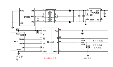
Figure 3: Constructing an Isolated Power Supply for ISO1410 Using SN6501
Another option for space-constrained applications is the ISOW78xx series devices, which provide signal and power isolation features in a small SOIC-16 package. The ISOW7841 can be used in combination with non-isolated RS-485 transceivers, as shown in the isolated RS-485 with integrated signal and power reference design. This combination occupies less space; no transformer is required, and it is easier to certify. Please visit the TI website, search for keywords, and refer to all documents in the online product folder for ISOW7841 for more details.
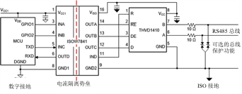
Figure 4: Using ISOW7841 to Create
Integrated Signal and Power Isolation for RS-485

Click “Read Original” to see more information about TI’s isolated RS-485 product line.