Click the blue text above
Follow us!

Do you want to learn about RS-485 transceiver design tutorials?This article provides some answers based on common questions from the TI E2E™ community, which will be a very useful resource if you want to learn more about this communication standard.
1. When is RS-485 bus termination needed, and how to terminate correctly?
RS-485 bus termination is useful in many applications, helping to improve signal integrity and reduce communication issues. “Termination” refers to matching the characteristic impedance of the cable with the termination network, allowing the receiver at the end of the bus to receive maximum signal power. Unterminated or improperly terminated buses will experience mismatch, causing reflections at the end of the network, leading to reduced overall signal integrity.
Termination is not required when the bidirectional loop time of the network is much greater than the signal bit time, as each reflection that reaches the end of the network will lose energy. However, for applications where the signal bit time is not significantly longer than the cable loop time, termination is crucial to minimize reflections.
Basic termination is called parallel termination, consisting of a single resistor, as shown in Figure 1. The RS-485 standard requires a nominal characteristic impedance of 120Ω, so the default resistance value for the termination resistor should be RT = 120Ω.
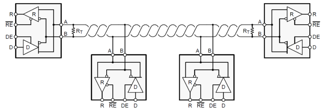
Figure 1: RS-485 bus with parallel termination
THVD1424 transceiver is a flexible RS-485 transceiver that integrates a 120Ω termination resistor between the driver and receiver bus pins. The termination resistor can be enabled or disabled via dedicated pins TERM_TX and TERM_RX, allowing system designers to flexibly use this transceiver in all node positions (intermediate or terminal nodes) for half-duplex or full-duplex networks.
2. What is fail-safe biasing, and how is it implemented?
The fail-safe biasing mechanism ensures that the RS-485 receiver does not enter an indeterminate state due to differential input voltage. The Electronic Industries Alliance (EIA)-485 standard specifies that when the differential voltage ≥+200mV, the RS-485 input threshold is a logic high level; when the differential voltage ≤-200mV, the RS-485 input threshold is a logic low level, leaving a 400mV indeterminate state between the high and low thresholds.
Fail-safe biasing can be implemented in two ways:
-
Select a transceiver with built-in fail-safe input thresholds.
-
Add external resistors to create an external bias when the bus is idle.
Both methods ensure that the bus remains in a logic high state.
3. How to calculate the maximum number of nodes on an RS-485 bus?
RS-485 is a multipoint differential bus, so all nodes on the bus share one transmission medium.As the total number of nodes increases, the load on each driver also increases.
The Telecommunications Industry Association (TIA)/EIA-485 standard specifies a hypothetical unit load (UL) to help calculate the maximum number of nodes on the RS-485 bus.The standard specifies that the driver must be able to drive at least 1.5V differential signals at up to 32 unit loads, with two 120Ω termination resistors in parallel at both ends of the bus.
Formula 1 represents the worst-case input voltage to leakage current ratio for calculating the input resistance. Once the input resistance of the nodes is determined, you can use Formula 2 to calculate the maximum number of nodes on the RS-485 bus:
Input Resistance = Max (VIN/Ileakage) (1)
No. of Nodes = 32/Input Resistance (2)
4. When is it necessary to add ground lines between nodes?
When designing remote data links, you must assume that some ground potential differences exist. These voltages create common-mode noise Vn in the transmitter output. It is unsafe to rely on local grounding as a reliable return current path, even if the total superimposed signal falls within the receiver’s input common-mode range. When the ground potential difference (GPD) exceeds the receiver’s common-mode range (which often occurs with longer cables and high current loads), appropriate grounding techniques will be required.
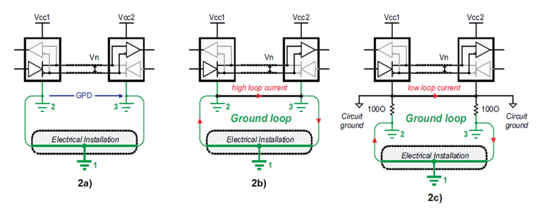
Figure 2: Remote node configuration: separate grounding (a);
directly connecting remote ground (b);
device ground and local system ground separated (c).
Figure 2a shows remote nodes that may draw power from different parts of the electrical device. Any changes to the device (e.g., during maintenance work) can increase the GPD to a level that exceeds the receiver’s input common-mode range. Therefore, a data link that works normally now may stop functioning in the future.
Direct remote grounding through ground lines (Figure 2b) is also not recommended, as direct connections can lead to large ground loop currents coupling common-mode noise onto the data lines.
To achieve direct remote grounding, the RS-485 standard recommends separating the device ground from the local system ground by inserting resistors (Figure 2c). Although this method reduces loop currents, the presence of large ground loops makes the data link sensitive to noise generated at some position in the loop. Thus, the stability of the data link cannot be guaranteed.
To withstand ground potential differences of up to several kilovolts on a stable RS-485 data link over long distances, the ideal approach is to electrically isolate the signal and power lines of the bus transceiver from its local signals and power. In this case, power isolators (such as isolated DC/DC converters) and signal isolators (such as digital capacitive isolators) can prevent current from flowing between remote system grounds and avoid creating current loops.
5. What are the recommended values for RS-485 length and speed?
At a given data rate, the maximum bus length is limited by transmission line losses and signal jitter. Data reliability drops sharply due to 10% or more jitter within the baud period. Figure 3 shows the characteristic curve of traditional RS-485 cable length versus data rate with 10% signal jitter.
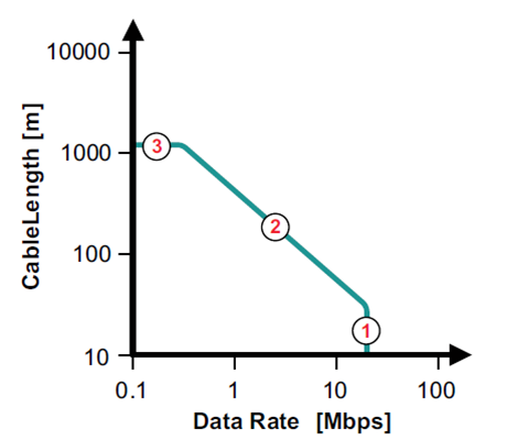
Figure 3: Recommended cable length versus data rate
In Figure 3, the circle marked as number 1 represents the high data rate region at short cable lengths. Here, the transmission line losses can be ignored; the data rate is primarily determined by the driver’s rise time. Although the recommended value for this standard is 10Mbps, today’s fast interface circuits can operate at data rates of up to 50Mbps.
The red area marked as number 2 in Figure 3 represents the transition from short data lines to long data lines. The losses of longer transmission lines must be taken into account. Therefore, as the cable length increases, the data rate must decrease. Empirically, the product of line length [m] and data rate [bps] should be 108.
The red number 3 represents a lower frequency range, where the interaction between the cable’s series resistance and the termination at the end of the line leads to signal attenuation. At some point, the signal amplitude becomes smaller than what the receiver can correctly detect (i.e., not exceeding the VIT threshold).
THVD1424 transceiver features an SLR (slew rate control) pin, supporting applications designed by system designers for low-speed (up to 500kbps) and fast (up to 20Mbps) applications.
6. How to estimate power loss in RS-485?
To calculate power loss, you can break the power down into several components. When the device is powered on without external load, the integrated circuit itself consumes power; if you add a load at its output pins, the device will provide power to drive the load. Since RS-485 has differential signals, the load is usually placed between the A and B pins.
In Figure 4, the blue trace PDic represents the power consumed by the device. For low data rates, power loss primarily comes from resistive loads (red trace) PDdc. At high data rates, power loss from capacitive loads (green trace) PDac must be considered.
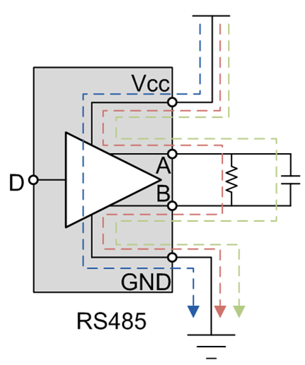
Figure 4: Calculation of different components of power loss
Formula 3 calculates the total power loss as follows:
PDtotal = PDic + PDdc + PDac (3)
To calculate total power loss, you first need to calculate the power consumed by each component. Formula 4 calculates the power loss of the device, where the static supply current Icc is specified in the datasheet:
PDic = Vcc*Icc (4)
If resistive loads are placed on the bus, the driver generates a voltage (Vod) across the resistive load, as shown in Formulas 5 and 6, where C is the parasitic capacitance, including transceiver capacitance, load capacitance, and lead capacitance. The data frequency f is also used in the calculations.
PDdc = Vcc*I – I²*R = (Vcc – I*R)*I (5)
PDac = 2*2C*f*Vcc*Vod (6)
7. How to protect RS-485 interfaces from electrostatic discharge (ESD)?
ESD protection can be categorized into several types, including Human Discharge Model, International Electrotechnical Commission (IEC) Contact Discharge, and IEC Air Gap Discharge. If the transceiver integrates IEC ESD protection (e.g., TI’s THVD1450 or THVD1500), no external components are needed to protect the RS-485 interface from specified ESD levels.
For example, THVD1450 provides 18kV IEC 61000-4-2 contact discharge protection without any external components. However, many devices on the market do not integrate this protection feature, so external Transient Voltage Suppressor (TVS) diodes may be required.
8. How to determine if external TVS diodes are needed?
Industrial networks must operate reliably in harsh environments. Electrical overstress transients caused by ESD, inductive load switching, or lightning strikes can disrupt data transmission and damage bus transceivers unless effective measures are taken to mitigate transient effects.
TI devices have been tested according to the following standards:
-
ESD immunity testing IEC 61000-4-2 simulates electrostatic discharge directly to adjacent electronic components by operators. THVD1500 and THVD1450 have been tested to meet this standard.
-
Electrical Fast Transient (EFT) or Burst Immunity Testing IEC 61000-4-4 simulates everyday switching transients caused by inductive load interruptions, relay contact bouncing, etc. THVD1450 and THVD1550 have been tested to meet this standard.
-
Surge Immunity Testing IEC 61000-4-5 is a very stringent transient immunity test involving current and duration, approximately 1,000 times longer than ESD and EFT tests. THVD1429 and THVD1419 have been tested to meet this standard.
TI THVD series new RS-485 transceivers integrate various levels of protection according to these standards and do not require additional external protection. The protection levels are specified in the device datasheet.
9. How to provide protection in case of short circuits at higher voltages?
In many RS-485 applications, communication lines may accidentally connect to power lines, especially in field-installed systems such as HVAC systems, lighting controls, or other building automation applications. In these cases, it is essential to ensure that the RS-485 transceiver is not damaged to avoid costs associated with returns or reinstallation.
While clamping devices like TVS diodes can limit the maximum voltage experienced by the transceiver during transient events, they typically cannot protect against prolonged stress (e.g., DC short circuits). In such cases, some series current-limiting component is needed. A typical approach is to use Positive Temperature Coefficient (PTC) resistors, which have low resistance under nominal conditions but increase resistance under fault conditions (e.g., when current flows to clamping devices like TVS).
However, using these additional series current-limiting and parallel voltage clamping devices can be costly and take up valuable PCB space. Therefore, in most cases, a better approach is to use transceivers that can withstand these high fault voltages without external protection. THVD2450 is an example, capable of withstanding DC short circuits of up to +/- 70V.
For more online technical support, please visit the TI E2E™ Chinese support forum (e2echina.ti.com).


Click “Read the Original” to learn more about TI RS-485 transceiver products!