The RS-485 bus has advantages such as a simple structure and low cost. However, when engineers set up RS-485 bus networks, they often encounter the question: should termination resistors be added to improve the reliability of the entire network’s communication? This article will answer that question.
1. The Role of Termination Resistors
For the RS-485 bus, termination resistors are primarily used to match the characteristic impedance of the communication line, preventing signal reflections and improving signal quality.
When setting up an RS-485 bus network, shielded twisted pair cables with a characteristic impedance of 120Ω are typically used. Since the input impedance of RS-485 transceivers is generally high (for example, the RSM485ECHT has an input impedance of 96kΩ and can connect up to 256 nodes), when the signal reaches the end of the bus, the instantaneous impedance change (for the RSM485ECHT, the impedance changes from 120Ω to 96kΩ) causes signal reflection, affecting the signal quality. The waveforms of the RSM485ECHT without and with termination resistors at a distance of 1200m and a communication rate of 500kbps are shown in Figures 1 and 2, respectively. The termination resistors significantly improved the signal quality.
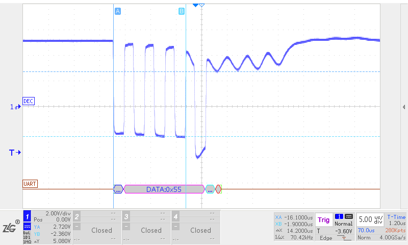
Figure 1: RSM485ECHT 1200m 500kbps without termination resistor
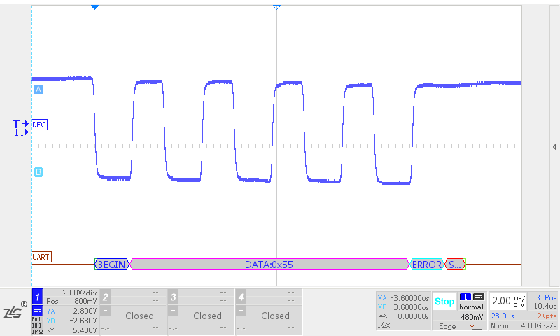
Figure 2: RSM485ECHT 1200m 500kbps with termination resistor
2. Problems Caused by Termination Resistors
While termination resistors can improve signal quality, they also present several issues:
1. Reduced Amplitude of the Driving Signal
The larger the load on the RS-485 bus, the lower the differential voltage amplitude output by the RS-485 transceiver. The waveforms of the RSM485ECHT without and with termination resistors at a distance of 5m and a communication rate of 500kbps are shown in Figures 3 and 4, respectively. It can be seen that the driving signal amplitude decreased by about 2V after adding termination resistors.
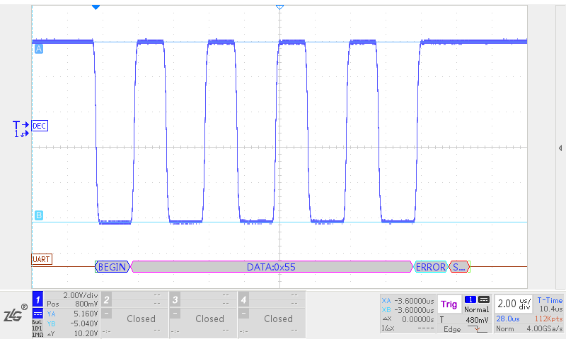
Figure 3: RSM485ECHT 5m 500kbps without termination
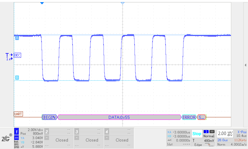
Figure 4: RSM485ECHT 5m 500kbps with termination
2. Increased Voltage Drop on the Communication Line
Adding termination resistors increases the current in the communication cable, resulting in a larger voltage drop and reducing the signal amplitude at the receiving end. The signal waveforms at the beginning and end of the RSM485ECHT at a distance of 1200m and a communication rate of 115.2kbps are shown in Figures 5 and 6 (using 0.75mm² communication wire). The signal at the end dropped by about 0.7V compared to the signal at the beginning.
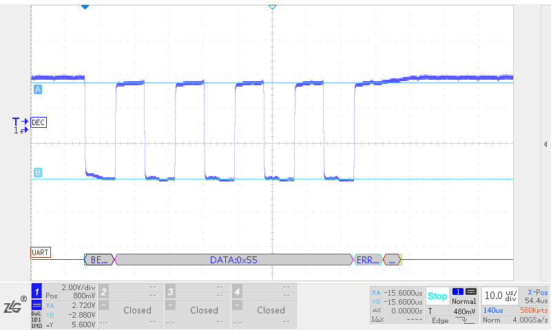
Figure 5: RSM485ECHT 1200m 115.2kbps with termination resistor – Beginning waveform
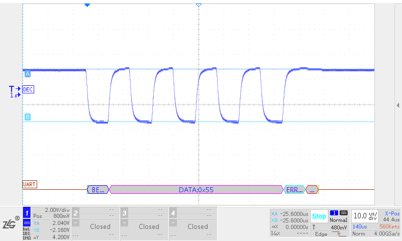
Figure 6: RSM485ECHT 1200m 115.2kbps with termination resistor – End waveform
3. Increased Power Consumption of the Transceiver
Adding termination resistors does not significantly affect the operating current in the receiving state, but it greatly increases the operating current in the driving state. For the RSM485ECHT, the operating current is about 20mA in receiving state and about 27mA without termination resistors and about 83mA with termination resistors in driving state. It can be seen that termination resistors greatly increase the power consumption of the RS-485 transceiver, and caution should be exercised when using termination resistors in applications with power consumption requirements.
4. Reduced Differential Voltage During Bus Idle State
Figure 7 shows a schematic diagram of communication between two RSM485ECHT modules.
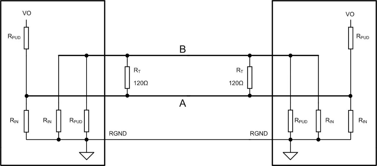
Figure 7: Equivalent schematic of RSM485ECHT communication
When both modules are in receiving state, the following formulas can be derived for nodes A and B based on Kirchhoff’s current law:
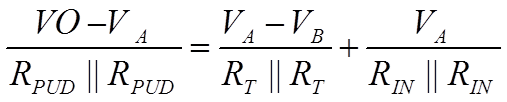
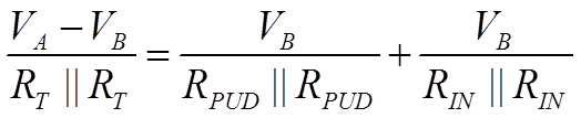
Where: RPUD is the built-in pull-up and pull-down resistor of the RSM485ECHT, 120kΩ; R¬IN is the input impedance of the RSM485ECHT, 96kΩ;
Based on the above formulas, the differential voltage between A and B can be calculated as:
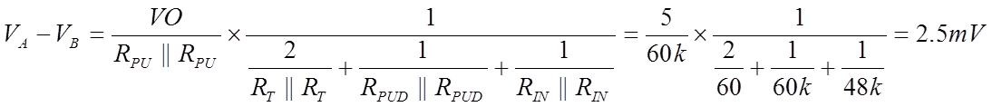
Since the threshold level of the RSM485ECHT is -200mV to -40mV, the module still outputs a high level under the above conditions, ensuring that the bus does not mistakenly receive data during idle states. However, for RS-485 transceivers with a threshold level of -200mV to +200mV, the output level is uncertain, which may cause erroneous data reception.
3. How to Solve the Idle State Problem After Adding Termination Resistors?
There are two solutions for the idle state problem:
1. Use modules similar to RSM485ECHT (threshold level of -200mV to -40mV). When the differential voltage of the RS-485 bus exceeds -40mV, the output of the RS-485 transceiver will be high.
2. Use modules like RSM485PCHT or RSM485PHT with output isolation power supply, which can pull the voltage of the RS-485 bus during idle states above +200mV by adding smaller pull-up and pull-down resistors externally (generally leaving a margin of 100mV or more), ensuring that the differential voltage of the RS-485 bus during idle states does not fall within the threshold range. However, the values of the pull-up and pull-down resistors should not be too small, generally the parallel value on the bus should be greater than 375Ω.
4. When Should Termination Resistors Be Added?
1. In cases of low communication speed or short communication distance, it is recommended not to add termination resistors.
In cases of low communication speed or short communication distance, the impact of signal reflections on communication signals is minimal, and not adding termination resistors can significantly reduce power consumption. Additionally, using larger pull-up and pull-down resistor values can ensure that the RS-485 bus has a high differential voltage amplitude during idle states, improving communication reliability.
2. In cases of longer communication distances and higher communication speeds, where signal quality is crucial.
In this case, termination resistors can be added to prevent signal reflection issues caused by impedance changes, improving signal quality, but it should be ensured that the differential voltage of the bus during idle states does not fall within the threshold range.
3. In cases where there are power consumption requirements and longer communication distances.
Generally, signals are sampled at the midpoint of a bit. Due to the longer bit duration at lower communication speeds, reflected signals are consumed before reaching the sampling point, having no impact on communication. The waveforms of the RSM485ECHT without termination resistors at a distance of 1200m and a communication rate of 9600bps are shown in Figures 8 and 9. It can be seen that reflected signals are consumed before reaching the midpoint of each bit.
Therefore, for applications with high power consumption requirements for RS-485 transceivers and longer communication distances, it is advisable to appropriately reduce communication speed.
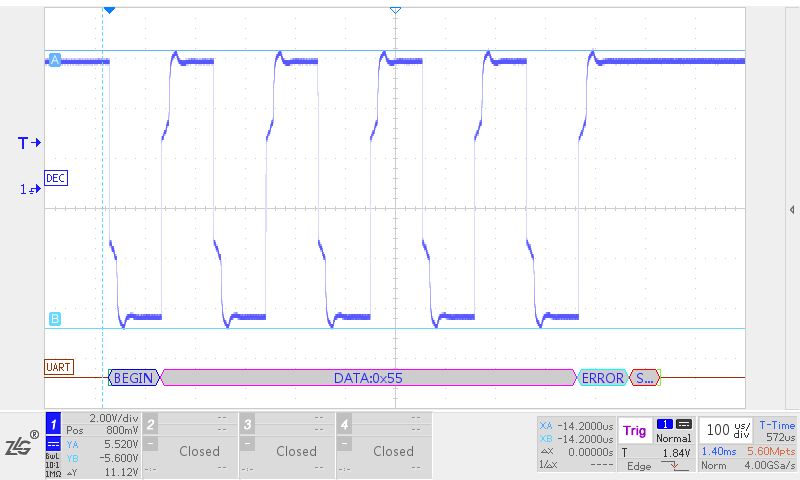
Figure 8: RSM485ECHT 1200m 9600bps without termination – Beginning waveform
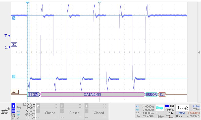
Figure 9: RSM485ECHT 1200m 9600bps without termination – End waveform
Reply with the keyword 【Power Supply】 to view more technical topics.
Official WeChat account introduction
Zhiyuan Electronics official WeChat account, a research and testing sharing platform gathering 500 engineers, providing you with leading product technology and solutions in the electronics industry.。