As an electronic engineer, the RS-485 serial interface is a fundamental and widely used topic that is often encountered in daily designs. So how can we quickly and effectively solve RS-485 circuit design issues in practical applications?
RS-485 Standard
The full name of the RS-485 standard is TIAA/EIA-485 serial communication standard. Data communication uses differential signaling, also known as balanced transmission, utilizing a pair of twisted pairs, where one line is defined as A and the other as B, as shown below:
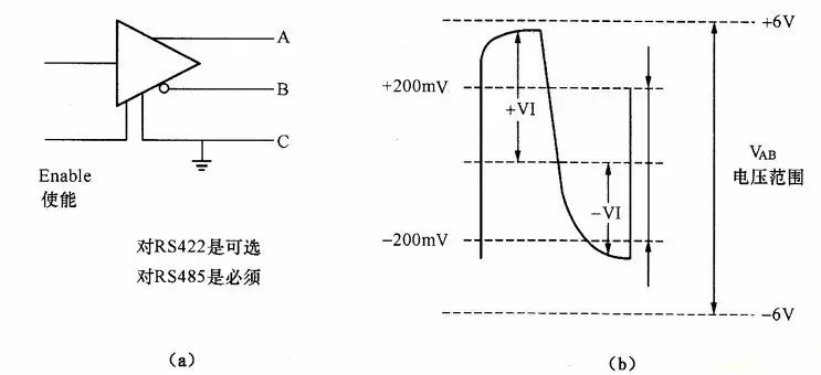
Typically, the positive level between the A and B sending drivers is +2 to +6V, representing one logic state, while the negative level is -2 to +6V, representing another logic state. There is also a signal ground C, and the RS-485 has an ‘enable’ pin, which is optional in RS-422. The ‘enable’ pin is used to control the connection and disconnection of the sending driver to the transmission line. When the ‘enable’ pin is active, the sending driver is in a high-impedance state, known as the ‘third state’, which is distinct from logic ‘1’ and ‘0’.
The receiver is defined in relation to the transmitter. The receive and transmit ends are connected through a balanced twisted pair, with AA and BB corresponding. When there is a voltage greater than +200mV between the AB at the receiving end, it outputs a positive logic level; when less than -200mV, it outputs a negative logic level. The voltage range that the receiver accepts on the balanced line is typically between 200mV and 6V.
RS-485 Precautions
1. RS-485 Network Installation
The RS-485 network topology typically uses a terminal-matching bus structure and does not support ring or star networks. This is mainly to reduce reflected signals (especially at nodes and points of discontinuity in bus impedance), which can affect signal quality.
2. RS-485 Terminal Matching
For RS-422 and RS-485 bus networks, termination resistors are generally required for matching. However, in short-distance and low-speed scenarios, termination matching can be ignored.
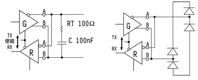
Terminal matching usually adopts termination resistor methods, typically using 120Ω in RS-485 networks, which corresponds to the characteristic impedance of the cable. This matching method is simple and effective, but the matching resistor consumes a significant amount of power, making it less suitable for systems with strict power limitations.
Another power-saving matching method is RC matching. By using a capacitor C to block the DC component, most power can be saved. However, choosing the value of capacitor C is challenging, requiring a compromise between power consumption and matching quality.
There is also a diode matching method. Although this scheme does not achieve true ‘matching’, it uses the clamping effect of the diode to quickly attenuate reflected signals, thereby improving signal quality. The energy-saving effect is significant.
3. RS-485 Grounding Issues
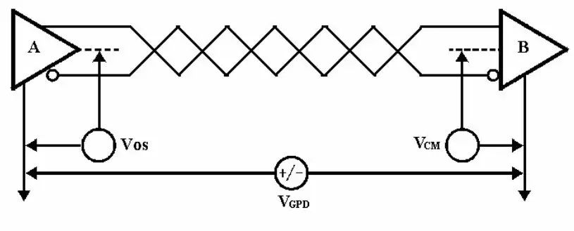
Grounding in electronic systems is crucial, and the grounding of the RS-485 transmission network is equally important, as an unreasonable grounding system can affect the stability of the entire network, primarily posing two major risks: common-mode interference and EMI.
Common-mode interference: The RS-485 interface employs differential signaling for transmission, and the transceiver has a certain common-mode voltage range; for instance, the common-mode voltage range for RS-485 transceivers is -7 to +12V. Only by meeting these conditions can the entire network function correctly. As shown below, common-mode interference caused by ground potential differences:
Electromagnetic interference (EMI) issue: The common-mode portion of the output signal from the driver requires a return path. Without a low-resistance return path (signal ground), it will return to the source in the form of radiation, causing the entire bus to act like a giant antenna radiating electromagnetic waves.
Countermeasures:
-
If the internal resistance of the interference source is not very small, consider adding a current-limiting resistor on the grounding line to restrict the interference current.
-
Use floating ground techniques to break the grounding loop.
-
Use isolation interfaces.
4. RS-485 Transient Protection
The grounding measures mentioned earlier only protect against low-frequency common-mode interference. For high-frequency transient interference, they are ineffective, as the lead inductance causes the grounding wire to effectively act as an open circuit for high-frequency transient interference. Such transient interference can reach hundreds or thousands of volts but lasts for a very short time. If not adequately protected, it can damage the interface. For such transient interference, isolation or bypass methods can be used for protection.
Overall Solution
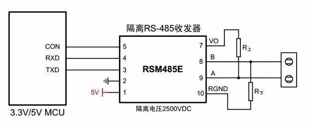
The above are several key considerations when designing RS-485, but in actual design, many uncontrollable factors exist. To help engineers avoid these headaches in design, Guangzhou Zhiyuan Electronics has launched integrated isolation, power supply, and bus protection RS-485 isolation transceiver modules since 2003. They have introduced a series of isolated RS-485 transceivers, such as RSM485CHT, RSM3485CT, RSM485ECHT, RSM485E, etc. The application of isolated RSM485 products not only eliminates the impact of ground loop potential differences and effectively resists common-mode interference but also protects the MCU side circuits in strong interference environments, significantly reducing the risk of interference and damage. With modular design, reliable applications, and competitive pricing, it helps users lower overall design risks and procurement costs.
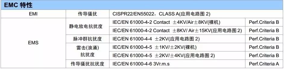
The RSM series isolated RS-485 transceivers comply with RoHS environmental certification, with conduction and radiation meeting EN55022 limits, ESD contact discharge of 4KV, air discharge of 8KV, EFT signal port of 4KV, and power port surge testing of 1KV, signal port of 2KV.
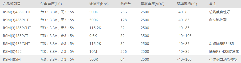
1. Model List
2. Typical Connection Circuit
3. EMC Characteristic Testing
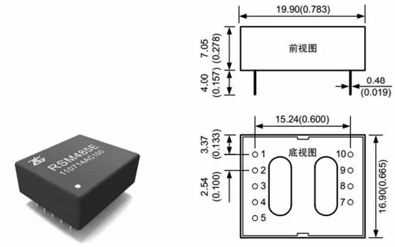
4. Module Physical Image and Dimensions
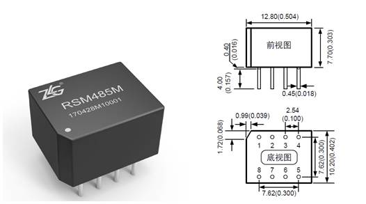
5. Ultra-Small Model RSM485M
For applications with limited PCB space or stringent size requirements for the final product, we can also choose the RSM485M model, which is only 1/3 the size of the conventional model, supporting a maximum of 64 nodes and a baud rate of 500kbps, making it a ‘little powerhouse’ among RS-485 isolation modules.
Reply with the keyword 【power supply】 to learn more about technical topics.
Official WeChat account of Zhiyuan Electronics, a research and testing sharing platform gathering 500 engineers, providing you with leading product technology and solutions in the electronics industry.。