Any form of communication requires rules to ensure everyone is on the same page. In electronics, these rules take the form of standards—these are widely applicable design specifications recommended by industry associations. Following these guidelines helps engineering devices speak the same electronic language, enabling efficient and reliable communication.
RS-232 (“RS” stands for “Recommended Standard”) was introduced in the 1960s as a standardized interface for serial communication. While it is still useful for this purpose, alternatives like RS-485 now exist, offering significantly enhanced performance. In this article, we will look at the most important differences between RS-232 and RS-485.
Point-to-Point vs. Multipoint
RS-232 is a point-to-point specification, meaning one RS-232 device can only communicate with another RS-232 device. Although some innovations allow RS-232 to be transformed into a “multipoint” network shared by multiple devices, the standard itself does not include this functionality.
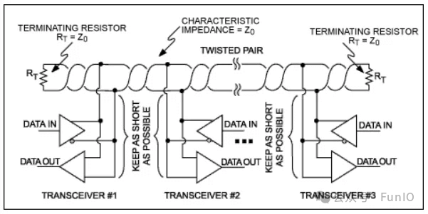
Because it is a multipoint specification, RS-485 is much more flexible. Multiple RS-485 devices can communicate without any special modifications or interface circuits, as shown in Figure 1. An RS-485 driver must be able to maintain 32 “unit loads,” meaning 32 receivers with an input impedance of 12 kΩ.
Voltage Levels
The original RS-232 standard specified logic levels of +25 V and -25 V. A typical home serial interface requires a 50 V signal swing, which is hard to believe, but this was over sixty years ago. Subsequent revisions of the standard reduced the signal swing to ±12 V, and then to ±5 V. The voltage levels in RS-485 are much lower—this is one of the most obvious differences between the two standards.
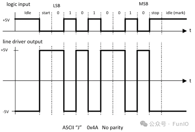
Figure 2 depicts a logic level data flow and the corresponding RS-232 version of that data flow. Note that in addition to the voltage level conversion, the polarity is also reversed. A +5 V logic high level becomes -5 V, while a 0 V logic low level becomes +5 V.
Single-Ended vs. Differential Signals
Typical logic level signals and RS-232 signals are single-ended, meaning an information signal requires one electrical signal. The electrical signal is referenced to a 0 V ground potential. RS-485 signals are differential, meaning an information signal requires two complementary electrical signals. The receiver extracts information by comparing the two signals.
Figure 3 illustrates the difference between single-ended and differential signals.
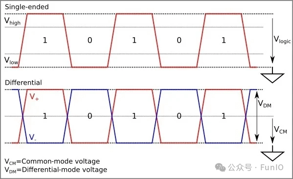
The signals generated by RS-485 compatible drivers have a minimum differential amplitude of 1.5 V; the minimum differential detection threshold for RS-485 receivers is 200 mV. This ensures that even if the signal significantly attenuates during transmission from the transmitter to the receiver, there is still enough margin to reliably detect digital data.
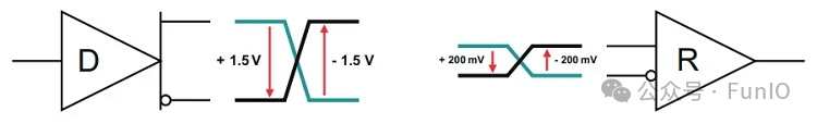
Figure 4 provides a visual representation of the minimum amplitudes for RS-485 drivers and receivers. The image source is a Texas Instruments application note titled “The RS-485 Design Guide[1]“, which is a great resource if you are looking for detailed information about the standard.
Signal Swing
The signal swing on the RS-485 bus is much lower than that of the RS-232 interface. This is a significant advantage of RS-485 because the smaller amplitude signals allow for simplified circuit design and improved efficiency. The lower amplitude combined with differential signaling does not increase the device’s sensitivity to electromagnetic interference. In fact, RS-485 communication is more robust than RS-232 communication.
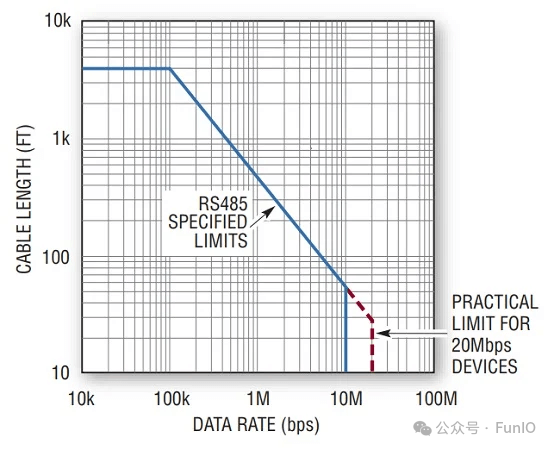
Another benefit associated with smaller amplitude signals is the higher data rate. The maximum data rate for RS-232 is about 1 Mbps. Theoretically, the maximum for RS-485 is 10 Mbps—in practice, as shown in Figure 5, the limits are higher.
Signal Encoding
RS-232 describes a complete solution for serial communication. It includes requirements for the following:
-
Electrical characteristics. -
Signal characteristics. -
Connection schemes. -
Mechanical interfaces.
In contrast, RS-485 only specifies electrical characteristics.
Neither standard defines a method for signal encoding. However, RS-232 typically uses a Universal Asynchronous Receiver/Transmitter (UART) signaling scheme, which defines start and stop bits, parity, and data encoding, among others. RS-485 also typically uses UART.
As shown in Figure 6, a UART data byte contains:
-
One start bit. -
Eight data bits. -
One stop bit.

If the receiver knows the transmitter’s data transmission rate, or baud rate, it can use an internal timer to correctly sample the incoming data bits. UART communication does not require additional signals to organize binary data blocks. It does not even require an external clock signal—the voltage levels are generated and interpreted by the internal timers of the transmitter and receiver, which are configured to the same baud rate.
RS-232 and RS-485 have similar names and purposes, but there are key differences in their specifications and implementation details. Their performance characteristics are also very different, with RS-485 exceeding RS-232 in nearly every aspect. While RS-232 can be a convenient and satisfactory interface for certain applications, RS-485 is a superior and more future-proof solution for serial communication.
References
The RS-485 Design Guide: https://www.ti.com/lit/an/slla272d/slla272d.pdf?ts=1710081041322