Follow our WeChat public account, click the top right corner of the public account homepage “ ··· ”, set a star mark to receive real-time updates on the latest news in smart automotive electronics and software.
Source: Automotive Maintenance and Repair
“Controller Area Network”, or CAN, is one of the most widely used field buses internationally. Originally, CAN was designed for microcontroller communication in automobiles, exchanging information between various electronic control units in the vehicle to form an automotive electronic control network. For example, the engine management system, transmission controller, instrument equipment, and electronic backbone system all embed CAN control devices.
In a single network composed of CAN bus, theoretically, countless nodes can be connected. In practical applications, the number of nodes is limited by the electrical characteristics of the network hardware. Common CAN line frequencies include:
250Kbs/500Kbs/1000Kbs, with different frequencies representing different transmission speeds.
 The CAN communication protocol mainly describes the method of information transfer between devices. The definition of the CAN layer is consistent with the Open Systems Interconnection (OSI) model. Each layer communicates with the corresponding layer on another device. Actual communication occurs between two adjacent layers on each device, while devices are interconnected through the physical medium of the physical layer of the model.
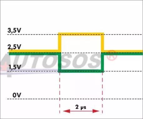
CAN can use various physical media, such as twisted pair cables and optical fibers. The most commonly used is twisted pair cable, where signals are transmitted using differential voltage. The two signal lines are referred to as “CAN_H” and “CAN_L”, and they are both around 2.5V when static, representing a logical “1”, also known as “dominant”. When CAN_H is higher than CAN_L, it represents a logical “0”, referred to as “recessive”; at this time, the typical voltage values are: CAN_H=3.5V and CAN_L=1.5V.
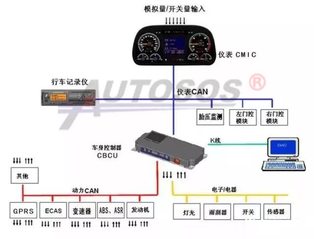
Vehicle Communication CAN Bus:
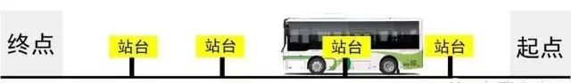
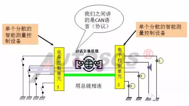
To make an analogy: the bus system, also known as CAN-BUS, actually operates similarly to a running bus. Each station is equivalent to a control unit, while the route is the CAN bus. Data is transmitted on the CAN bus, just as passengers are carried on the bus. When a control unit receives information from a sensor responsible for sending data to it, it analyzes and processes this information, taking appropriate actions and sending this information onto the bus system. This information will then be transmitted across the bus system, and each control unit connected to the bus system will receive this information. If the information is useful to it, it will store it; if not, it will ignore it.
Communication Principles of the CAN Bus
First Method: “Each piece of information is exchanged through its own independent data line”
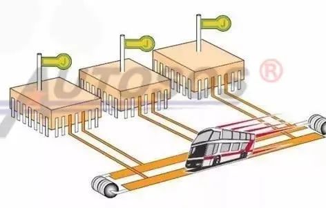
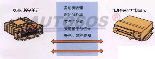
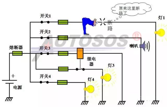
Currently, there are two forms of information transmission used in vehicles. The first is that each piece of information is exchanged through its own independent data line. For example, if there are five types of information that need to be transmitted between two control units, then five independent data lines are required. This means the more types of information, the greater the number of data lines and the pin count of the control units. These complex and numerous wiring harnesses undoubtedly increase the weight of the vehicle and pose certain difficulties for overall vehicle wiring.
Second Method: “All information is exchanged through two data lines”
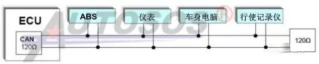
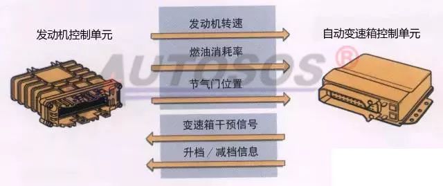
The second method is that all information between control units is exchanged through two data lines, known as the CAN data bus. Through this method, all information, regardless of its size, can be transmitted over these two data lines, significantly improving the overall system’s operational efficiency. For instance, a typical computer keyboard has 104 keys but can send hundreds of different commands, yet the data connection between the keyboard and the computer has only seven wires. The keyboard relies on different coded signals sent over these seven data connection wires to transmit information. The principle of the CAN data bus is similar. This change from a one-line-per-use system to a one-line-multiple-use system can greatly reduce the number of wires in a car and simplify the overall vehicle wiring.
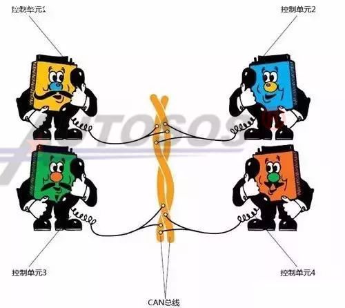
Having understood that two control units communicate via two data lines, we can extend this to multiple control units. In fact, communication between multiple control units is achieved by connecting each control unit to these two CAN buses, enabling information sharing among multiple control units.
The entire principle is very similar to a conference call. One telephone user (control unit) sends data into the network, and other users “answer” this data. Users interested in this data will utilize it, while others will choose to ignore it.
Design of CAN Communication
1. Why are there two twisted pairs in CAN lines?
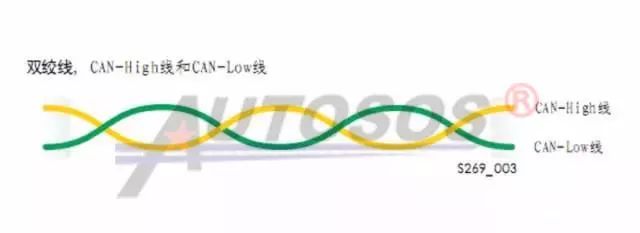
For clarity, the CAN wires are represented in solid colors: the CAN-High line is always yellow, and the CAN-Low line is always green. (The specific colors of CAN wires depend on the main vehicle manufacturer’s design and may vary, but they are generally designed to be easily distinguishable from other vehicle wiring.)
The two wires of the CAN data bus are called CAN-High and CAN-Low. The two twisted wires together are referred to as twisted pair cable.
In principle, a single wire is sufficient to meet the functional requirements of the CAN bus, but a second wire is still equipped in this bus system. The signal voltage on this second wire mirrors that of the first, effectively suppressing external interference.
2. Why is the CAN bus designed with high and low voltages?
The CAN data bus: used to transmit data, consists of CAN high (CAN-high) and low (CAN-low) data lines. Data is sent to each control unit without a specified receiver, and each control unit performs calculations after receiving the data. To prevent external electromagnetic interference and radiation, the CAN bus uses two wires twisted together, with opposite potentials on each wire. During operation, the CAN high voltage ranges from 2.5V to 3.5V, and the CAN low voltage ranges from 1.5V to 2.5V. When measured statically, the CAN high voltage is around 2.6V, and the CAN low voltage is around 2.4V. This design protects the CAN bus from external electromagnetic interference while maintaining a neutral radiation level, i.e., no radiation.
What is a Communication Protocol?
It is the principle that electronic control units follow when exchanging information. In simple terms, for the electronic control units in a network to communicate smoothly, they must speak the same language; the protocol is equivalent to a language. For example, the commonly used CAN bus design in commercial vehicles is based on the J1939 protocol.
Comparison of Traditional Wiring and CAN Communication Bus
In traditional electrical control systems, there are many electrical components; each additional component adds a potential failure point. If functionality needs to be added or changed, it involves modifying wiring harnesses, switches, or adding relays, which can be cumbersome. Complex functionalities, such as displaying engine faults in Chinese or cruise control, cannot be implemented.
2. CAN Communication Bus:
Advantages of the CAN Bus:
1> It meets the complex communication needs between more computer modules, with higher efficiency. Long-distance data transmission (up to 10Km); high-speed data transmission rates (up to 1Mbit/s).
2> It saves development and design costs for new products. CAN nodes can be added without expansion, with strong scalability, and rapid product upgrades, without modifying existing wiring harnesses.
3> The bus control system replaces traditional fuses and relays, reducing the number of components, thereby minimizing failure points.
4> The bus control system reduces the length of wiring harnesses. The longer the harness, the more prone it is to failures. It minimizes vehicle wiring, further reducing costs. With bus technology, signal transmission between modules only requires two signal wires. Wiring becomes localized, and all other wires that run across the vehicle are no longer needed, saving wiring costs. Additionally, data sharing also saves wiring harnesses.
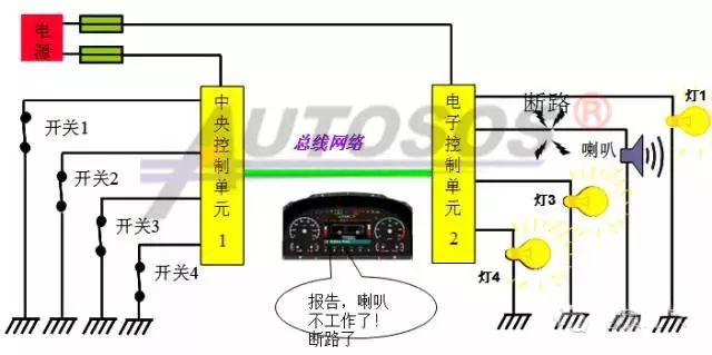
5> Circuit protection function: In the event of a short circuit, the CBCU will automatically cut off the power output to that line, protecting the circuit and simultaneously sending fault information to the instrument, which will report the relevant fault.
6> When a fault occurs in a certain electrical system, the electronic control module will display this fault on the instrument for easy repair.
Why are termination resistors installed at both ends of the CAN bus?
Termination resistors are designed to be installed at both ends of the automotive CAN bus!
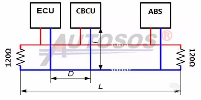
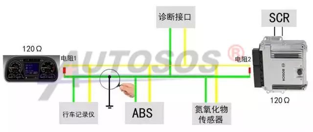
1. If the ECU itself does not have a 120Ω resistor, two 120Ω resistors need to be installed in parallel at the ends of the CAN network:
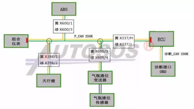
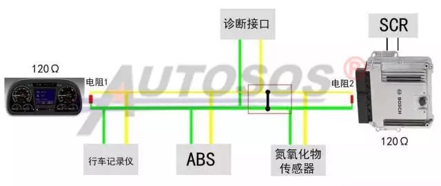
2. Some CAN bus computers already have built-in resistors, as shown below (taking the DeLong natural gas CAN bus as an example):
The role of termination resistors: The termination resistor at the data transmission endpoint prevents data reflection that could corrupt the data and affect CAN network data transmission. Therefore, termination resistors are designed and installed in the CAN bus.
1. The CAN network has two 120-ohm termination resistors, so when measuring the resistance of the two CAN lines in the CAN network, it should normally be 60 ohms (the two 120 resistors in parallel result in 60 ohms; in rare cases, some models may measure 40 ohms, indicating that three devices have 120-ohm resistors, which can also communicate normally; this is something to be aware of).)
2. Under normal circumstances, the voltage of CANH is between 1.5-3.5V, and the voltage of CANL is between 1.5-2.5V.
What is a CAN Communication Node?
1. The CAN communication bus enables information sharing between ECU, CBCU, ABS, CAN instruments, and other CAN devices, such as water temperature and oil pressure. Only the ECU needs to install sensors to transmit the current measured water temperature and oil pressure to the CAN instruments in real-time. The CAN instruments do not need to install separate water temperature and oil pressure sensors.
2. Only CAN devices can use the CAN bus. Sometimes a vehicle may have several CAN devices, such as ECU, CAN instruments, NOx sensors, etc. Each CAN device is referred to as a node, with the ECU being node A;
3. In our maintenance work, a common fault “CAN node A bus error” does not necessarily indicate a fault in the ECU itself; it is usually caused by abnormal CAN network voltage or other CAN control faults leading to interference in the CAN network.
Troubleshooting Common CAN Bus Faults
1. Common Fault: CAN High Shorted to Power
1> Turn the ignition switch to the ON position, powering all nodes in the vehicle;
2> Set the multimeter to the voltage range;
3> Connect the positive probe of the multimeter to the diagnostic interface pin CAN_H, and the negative probe to ground (GND), testing the CAN-H voltage: if the voltage is around 2.6V, it indicates normal; if the voltage is greater than 5V or battery voltage, it indicates a short circuit between CAN-H and high power;
2. Common Fault: CAN Low Shorted to Power
1> Turn the ignition switch to the ON position, powering all nodes in the vehicle;
2> Set the multimeter to the voltage range;
3> Connect the positive probe of the multimeter to the diagnostic interface pin CAN_L, and the negative probe to ground (GND), testing the CAN-L voltage: if the voltage is around 2.4V, it indicates normal; if the voltage is greater than 5V or battery voltage, it indicates a short circuit between CAN-L and high power;
3. Common Fault: CAN High Shorted to Ground
1> Disconnect the positive terminal of the battery to cut power to the vehicle;
2> Set the multimeter to the resistance range;
3> Connect the positive probe of the multimeter to the diagnostic interface pin CAN_H, and the negative probe to ground (GND), testing the resistance of CAN-H to ground. If the resistance is greater than 100KΩ, it is normal. If the resistance is too low, there is a short circuit condition on the CAN high line to ground.
4. Common Fault: CAN Low Shorted to Ground
1> Disconnect the positive terminal of the battery to cut power to the vehicle;
2> Set the multimeter to the resistance range;
3> Connect the positive probe of the multimeter to the diagnostic interface pin CAN_L, and the negative probe to ground (GND), testing the resistance of CAN-L to ground. If the resistance is greater than 100KΩ, it is normal. If the resistance is too low, there is a short circuit condition on the CAN low line to ground.
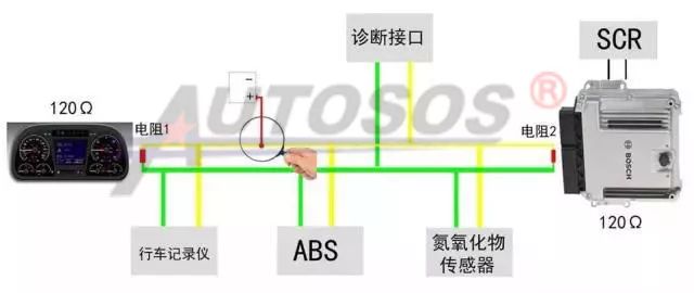
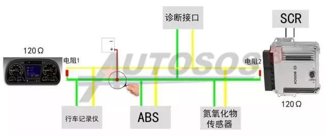
5. Common Fault: Short Circuit Between CAN High and CAN Low Lines
1> Disconnect the positive terminal of the battery to cut power to the vehicle;
2> Set the multimeter to the resistance range;
3> Connect the multimeter probes to the diagnostic interface pins CAN_H and CAN_L, testing for a short circuit between CAN-H and CAN-L. Since the entire CAN bus is equipped with 120Ω resistors in parallel, the normal measurement for the resistance between CAN high and CAN low should be around 60Ω. If the result is abnormal, check for short circuits or open circuits in the CAN high and low lines.
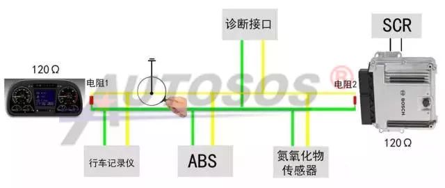
Note: Another scenario is that the termination resistors (either internal to the computer or external resistors) may have issues, leading to CAN high and CAN low resistance values not being around 60Ω.
The CAN communication protocol mainly describes the method of information transfer between devices. The definition of the CAN layer is consistent with the Open Systems Interconnection (OSI) model. Each layer communicates with the corresponding layer on another device. Actual communication occurs between two adjacent layers on each device, while devices are interconnected through the physical medium of the physical layer of the model.
CAN can use various physical media, such as twisted pair cables and optical fibers. The most commonly used is twisted pair cable, where signals are transmitted using differential voltage. The two signal lines are referred to as “CAN_H” and “CAN_L”, and they are both around 2.5V when static, representing a logical “1”, also known as “dominant”. When CAN_H is higher than CAN_L, it represents a logical “0”, referred to as “recessive”; at this time, the typical voltage values are: CAN_H=3.5V and CAN_L=1.5V.
Vehicle Communication CAN Bus:
To make an analogy: the bus system, also known as CAN-BUS, actually operates similarly to a running bus. Each station is equivalent to a control unit, while the route is the CAN bus. Data is transmitted on the CAN bus, just as passengers are carried on the bus. When a control unit receives information from a sensor responsible for sending data to it, it analyzes and processes this information, taking appropriate actions and sending this information onto the bus system. This information will then be transmitted across the bus system, and each control unit connected to the bus system will receive this information. If the information is useful to it, it will store it; if not, it will ignore it.
Communication Principles of the CAN Bus
First Method: “Each piece of information is exchanged through its own independent data line”
Currently, there are two forms of information transmission used in vehicles. The first is that each piece of information is exchanged through its own independent data line. For example, if there are five types of information that need to be transmitted between two control units, then five independent data lines are required. This means the more types of information, the greater the number of data lines and the pin count of the control units. These complex and numerous wiring harnesses undoubtedly increase the weight of the vehicle and pose certain difficulties for overall vehicle wiring.
Second Method: “All information is exchanged through two data lines”
The second method is that all information between control units is exchanged through two data lines, known as the CAN data bus. Through this method, all information, regardless of its size, can be transmitted over these two data lines, significantly improving the overall system’s operational efficiency. For instance, a typical computer keyboard has 104 keys but can send hundreds of different commands, yet the data connection between the keyboard and the computer has only seven wires. The keyboard relies on different coded signals sent over these seven data connection wires to transmit information. The principle of the CAN data bus is similar. This change from a one-line-per-use system to a one-line-multiple-use system can greatly reduce the number of wires in a car and simplify the overall vehicle wiring.
Having understood that two control units communicate via two data lines, we can extend this to multiple control units. In fact, communication between multiple control units is achieved by connecting each control unit to these two CAN buses, enabling information sharing among multiple control units.
The entire principle is very similar to a conference call. One telephone user (control unit) sends data into the network, and other users “answer” this data. Users interested in this data will utilize it, while others will choose to ignore it.
Design of CAN Communication
1. Why are there two twisted pairs in CAN lines?
For clarity, the CAN wires are represented in solid colors: the CAN-High line is always yellow, and the CAN-Low line is always green. (The specific colors of CAN wires depend on the main vehicle manufacturer’s design and may vary, but they are generally designed to be easily distinguishable from other vehicle wiring.)
The two wires of the CAN data bus are called CAN-High and CAN-Low. The two twisted wires together are referred to as twisted pair cable.
In principle, a single wire is sufficient to meet the functional requirements of the CAN bus, but a second wire is still equipped in this bus system. The signal voltage on this second wire mirrors that of the first, effectively suppressing external interference.
2. Why is the CAN bus designed with high and low voltages?
The CAN data bus: used to transmit data, consists of CAN high (CAN-high) and low (CAN-low) data lines. Data is sent to each control unit without a specified receiver, and each control unit performs calculations after receiving the data. To prevent external electromagnetic interference and radiation, the CAN bus uses two wires twisted together, with opposite potentials on each wire. During operation, the CAN high voltage ranges from 2.5V to 3.5V, and the CAN low voltage ranges from 1.5V to 2.5V. When measured statically, the CAN high voltage is around 2.6V, and the CAN low voltage is around 2.4V. This design protects the CAN bus from external electromagnetic interference while maintaining a neutral radiation level, i.e., no radiation.
What is a Communication Protocol?
It is the principle that electronic control units follow when exchanging information. In simple terms, for the electronic control units in a network to communicate smoothly, they must speak the same language; the protocol is equivalent to a language. For example, the commonly used CAN bus design in commercial vehicles is based on the J1939 protocol.
Comparison of Traditional Wiring and CAN Communication Bus
In traditional electrical control systems, there are many electrical components; each additional component adds a potential failure point. If functionality needs to be added or changed, it involves modifying wiring harnesses, switches, or adding relays, which can be cumbersome. Complex functionalities, such as displaying engine faults in Chinese or cruise control, cannot be implemented.
2. CAN Communication Bus:
Advantages of the CAN Bus:
1> It meets the complex communication needs between more computer modules, with higher efficiency. Long-distance data transmission (up to 10Km); high-speed data transmission rates (up to 1Mbit/s).
2> It saves development and design costs for new products. CAN nodes can be added without expansion, with strong scalability, and rapid product upgrades, without modifying existing wiring harnesses.
3> The bus control system replaces traditional fuses and relays, reducing the number of components, thereby minimizing failure points.
4> The bus control system reduces the length of wiring harnesses. The longer the harness, the more prone it is to failures. It minimizes vehicle wiring, further reducing costs. With bus technology, signal transmission between modules only requires two signal wires. Wiring becomes localized, and all other wires that run across the vehicle are no longer needed, saving wiring costs. Additionally, data sharing also saves wiring harnesses.
5> Circuit protection function: In the event of a short circuit, the CBCU will automatically cut off the power output to that line, protecting the circuit and simultaneously sending fault information to the instrument, which will report the relevant fault.
6> When a fault occurs in a certain electrical system, the electronic control module will display this fault on the instrument for easy repair.
Why are termination resistors installed at both ends of the CAN bus?
Termination resistors are designed to be installed at both ends of the automotive CAN bus!
1. If the ECU itself does not have a 120Ω resistor, two 120Ω resistors need to be installed in parallel at the ends of the CAN network:
2. Some CAN bus computers already have built-in resistors, as shown below (taking the DeLong natural gas CAN bus as an example):
The role of termination resistors: The termination resistor at the data transmission endpoint prevents data reflection that could corrupt the data and affect CAN network data transmission. Therefore, termination resistors are designed and installed in the CAN bus.
1. The CAN network has two 120-ohm termination resistors, so when measuring the resistance of the two CAN lines in the CAN network, it should normally be 60 ohms (the two 120 resistors in parallel result in 60 ohms; in rare cases, some models may measure 40 ohms, indicating that three devices have 120-ohm resistors, which can also communicate normally; this is something to be aware of).)
2. Under normal circumstances, the voltage of CANH is between 1.5-3.5V, and the voltage of CANL is between 1.5-2.5V.
What is a CAN Communication Node?
1. The CAN communication bus enables information sharing between ECU, CBCU, ABS, CAN instruments, and other CAN devices, such as water temperature and oil pressure. Only the ECU needs to install sensors to transmit the current measured water temperature and oil pressure to the CAN instruments in real-time. The CAN instruments do not need to install separate water temperature and oil pressure sensors.
2. Only CAN devices can use the CAN bus. Sometimes a vehicle may have several CAN devices, such as ECU, CAN instruments, NOx sensors, etc. Each CAN device is referred to as a node, with the ECU being node A;
3. In our maintenance work, a common fault “CAN node A bus error” does not necessarily indicate a fault in the ECU itself; it is usually caused by abnormal CAN network voltage or other CAN control faults leading to interference in the CAN network.
Troubleshooting Common CAN Bus Faults
1. Common Fault: CAN High Shorted to Power
1> Turn the ignition switch to the ON position, powering all nodes in the vehicle;
2> Set the multimeter to the voltage range;
3> Connect the positive probe of the multimeter to the diagnostic interface pin CAN_H, and the negative probe to ground (GND), testing the CAN-H voltage: if the voltage is around 2.6V, it indicates normal; if the voltage is greater than 5V or battery voltage, it indicates a short circuit between CAN-H and high power;
2. Common Fault: CAN Low Shorted to Power
1> Turn the ignition switch to the ON position, powering all nodes in the vehicle;
2> Set the multimeter to the voltage range;
3> Connect the positive probe of the multimeter to the diagnostic interface pin CAN_L, and the negative probe to ground (GND), testing the CAN-L voltage: if the voltage is around 2.4V, it indicates normal; if the voltage is greater than 5V or battery voltage, it indicates a short circuit between CAN-L and high power;
3. Common Fault: CAN High Shorted to Ground
1> Disconnect the positive terminal of the battery to cut power to the vehicle;
2> Set the multimeter to the resistance range;
3> Connect the positive probe of the multimeter to the diagnostic interface pin CAN_H, and the negative probe to ground (GND), testing the resistance of CAN-H to ground. If the resistance is greater than 100KΩ, it is normal. If the resistance is too low, there is a short circuit condition on the CAN high line to ground.
4. Common Fault: CAN Low Shorted to Ground
1> Disconnect the positive terminal of the battery to cut power to the vehicle;
2> Set the multimeter to the resistance range;
3> Connect the positive probe of the multimeter to the diagnostic interface pin CAN_L, and the negative probe to ground (GND), testing the resistance of CAN-L to ground. If the resistance is greater than 100KΩ, it is normal. If the resistance is too low, there is a short circuit condition on the CAN low line to ground.
5. Common Fault: Short Circuit Between CAN High and CAN Low Lines
1> Disconnect the positive terminal of the battery to cut power to the vehicle;
2> Set the multimeter to the resistance range;
3> Connect the multimeter probes to the diagnostic interface pins CAN_H and CAN_L, testing for a short circuit between CAN-H and CAN-L. Since the entire CAN bus is equipped with 120Ω resistors in parallel, the normal measurement for the resistance between CAN high and CAN low should be around 60Ω. If the result is abnormal, check for short circuits or open circuits in the CAN high and low lines.
Note: Another scenario is that the termination resistors (either internal to the computer or external resistors) may have issues, leading to CAN high and CAN low resistance values not being around 60Ω.
Note: If there are no abnormalities in the above tests, but the instrument still reports a bus communication fault, this may indicate a special fault situation. Based on experience, it could be one of the following faults:
1. A power disconnection in a certain node, leading to no messages being sent.
2. A certain node does not meet the 250kbps communication rate.
3. A fault within a certain node itself.
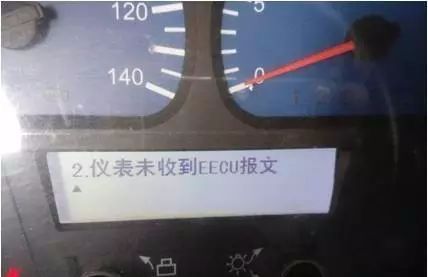
The Tianlong instrument displays: Instrument did not receive EECU message
This fault occurs when the engine ECU is not powered on and activated, causing the ECU to be unable to send data information to the instrument, resulting in the instrument not receiving data from the ECU and reporting: Instrument did not receive EECU message.
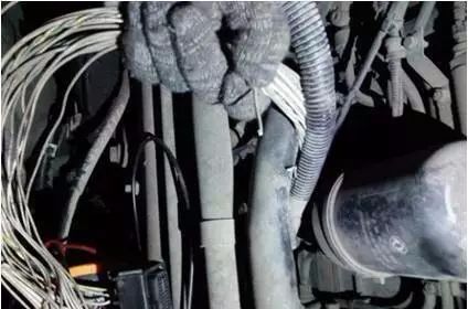
Investigation revealed that the issue was caused by oxidation and disconnection of the wake-up line at pin 1.40 supplied by the key to the computer board.
This fault generally has three scenarios:
1. The ECU or internal communication module is damaged and cannot send or receive data information.
2. The ECU is not powered on and cannot send data information.
3. Fault in the CAN line between the ECU and the vehicle computer VECU.
Weichai Bosch 2.2 post-treatment reports fault code P0050
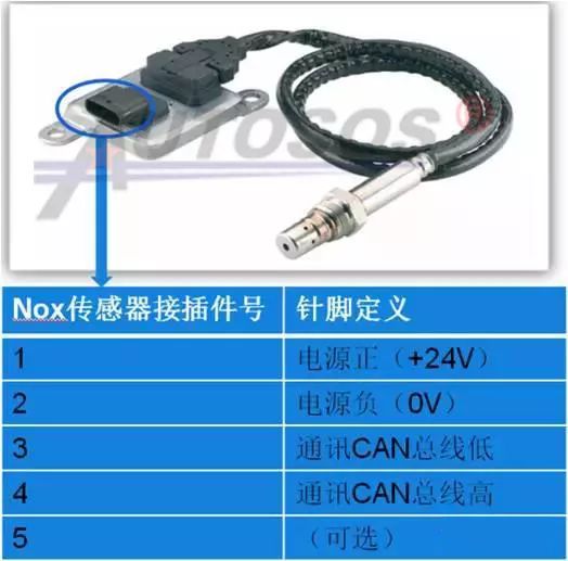
The Weichai paired with Bosch 2.2 post-treatment currently reports the fault code: CAN reception frame AT101 timeout. This fault code indicates that the ECU failed to receive data information sent from the NOx sensor.
Common fault causes are as follows:
1. Abnormal power supply to the NOx sensor, preventing it from functioning normally and sending data information.
2. Internal fault in the sensor, preventing it from sending data information.
3. Fault in the CAN-L and CAN-H lines of the sensor.
 Follow our WeChat public account, click the top right corner of the public account homepage “ ··· ”, set a star mark to receive real-time updates on the latest news in smart automotive electronics and software.
【Disclaimer】 The article reflects the author’s independent views and does not represent the position of Wangcai Automotive Electronics. If there are issues regarding content or copyright, please contact Wangcai Automotive Electronics within 30 days of publication for deletion or negotiation of copyright usage.