Skip to content
What Is the Trigger Mode of an Oscilloscope?
The “trigger” of an oscilloscope is to synchronize the oscilloscope’s scanning with the observed signal, thus displaying a stable waveform. Different “trigger modes” are required to meet various observation needs. The basic trigger modes of an oscilloscope are three:
The first is “Auto Mode (AUTO)”:
In this mode, when no trigger occurs, the oscilloscope’s scanning system automatically scans according to the set scanning rate;
and when a trigger occurs, the scanning system scans according to the signal’s frequency as much as possible. Therefore, in this mode, regardless of whether the trigger conditions are met, the oscilloscope will produce scans, and changes in the scan lines will be visible on the screen, which is a characteristic of this mode.
The second is “Normal Mode (NORM)”:
This mode is different from auto mode; in this mode, the oscilloscope will only scan when the trigger conditions are met. If there is no trigger, it will not scan.
Therefore, in this mode, if there is no trigger, for analog oscilloscopes, no scan lines will be visible, and the screen will show nothing. For digital oscilloscopes, the waveform will not update, and not understanding this may often lead to the assumption that the signal is not connected or some other fault.
The third is “Single Mode (SINGLE)”:
This mode is somewhat similar to “Normal Mode”, meaning it will only scan when the trigger conditions are met; otherwise, it will not scan.
However, the difference is that once a scan is generated and completed, the oscilloscope’s scanning system enters a resting state, and even if subsequent signals meet the trigger conditions, it will not scan again. In other words, it triggers once and scans once, and the scanning system must be manually restarted to generate the next trigger.
Clearly, for ordinary analog oscilloscopes, in this mode, you will often find that nothing is visible because the waveform flashes by, and the oscilloscope cannot retain it. In most cases, this mode is of little use. The above three trigger modes are provided by the vast majority of oscilloscopes.
How to Choose and Use in Practice?
In practical use, the choice of different trigger modes should be based on the characteristics of the observed signal and the content to be observed, and there are no fixed rules; it is often an interactive process. By selecting different trigger modes, one can understand the characteristics of the signal and then choose an effective trigger mode based on the signal’s characteristics and the desired observation content.
In this process, it is most important to understand the working mechanism of different trigger modes, to know the characteristics of the observed signal, and to clarify the content to be observed.
Generally speaking, when the characteristics of the signal are not well understood, one should choose auto mode because, at this time, regardless of what the signal is, the oscilloscope will scan, and you will at least see something on the screen, even if it is just the scan line, rather than seeing nothing.
Once there are scan lines, you can find the waveform by adjusting the vertical gain, vertical position, time base rate, and other parameters, and then stabilize the waveform by selecting the trigger source, trigger edge, and trigger level.
For analog oscilloscopes, as long as the signal is periodic, within the appropriate observation range of the corresponding oscilloscope, and not too complex, this step generally provides a good understanding of the signal, and further observation can be made as needed.
For normal mode, many friends may feel that there is no difference in observation effect compared to auto mode. Often, when switching the trigger mode between auto and normal, the waveform on the screen does not change. However, this situation usually occurs only when the observed signal is a relatively simple periodic signal.
The role of normal mode is to observe waveform details, especially for more complex signals, such as video sync signals. Why is this the case?
This is because to observe details, we must increase the time base scanning rate to expand the waveform. When we do this, the frequency of the observed signal becomes lower relative to the oscilloscope’s scanning rate, meaning that the oscilloscope may perform many scans between two triggers.
In this case, if we select auto mode, the oscilloscope will actually perform all these scans, resulting in the displayed waveforms (which are not triggered) being shown alongside the waveforms corresponding to the triggered scans, causing the displayed waveforms to overlap and thus failing to clearly show the waveform we want to see.
However, if we choose normal mode, the oscilloscope will not perform these scans between triggers, only performing scans caused by triggers, thus only displaying the waveforms related to the trigger, making the waveform clearer. This is the function of normal trigger mode.
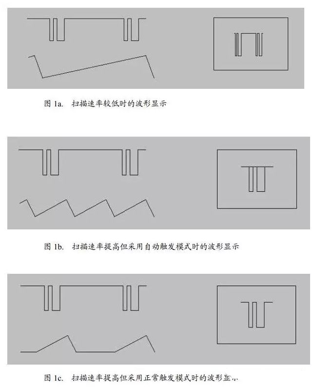
Figure 1 illustrates this situation. In Figure 1, the upper left shows the observed waveform, the lower part shows the scanning waveform, and the right side shows the displayed waveform.
In Figure 1a, the scanning rate is low, making it inconvenient to observe waveform details;
Figure 1b increases the scanning rate, using auto trigger mode, and the displayed waveform is unclear, with overlapping phenomena;
Figure 1c has the same scanning rate as Figure 1b, but uses normal triggering, scanning only when triggered, thus displaying a clear waveform.
Above, we briefly described the basic trigger modes of oscilloscopes and considerations for their practical use, hoping to assist beginners in mastering the oscilloscope.
In addition to the content discussed in this article, adjusting other parameters of the oscilloscope is also very important. Users need to have a clear understanding of the meaning of various parameter adjustments.
On the other hand, they also need to understand the characteristics of the observed signal and clarify the observation targets to effectively use the oscilloscope to achieve measurement and testing purposes.
How to Use the Oscilloscope Effectively?
For power engineers, once there is a problem with a product, they need to capture waveforms, capture timings, and test accurate values to help engineers analyze and address issues. Speaking with facts, seeing waveforms speak. How to ensure the accuracy and reliability of test data is very important.
Accurate numbers can help us, while distorted waveforms and values can mislead us, driving us off course and causing us to waste unnecessary effort.
Thinking carefully, although I am not an expert in oscilloscopes, I have read many articles about oscilloscopes and encountered many problems in practice, solving many issues along the way. I have some experience to share, and I hope it can help everyone. If the writing is not good, please forgive me.
I often see many small companies using low-end oscilloscopes with low bandwidth and sampling rates, believing that it is sufficient to capture waveforms, thinking there is no need to buy better oscilloscopes, and believing that operating an oscilloscope is simple without many specifications.
Seeing them operate the oscilloscope without preparing before testing, just picking it up and using it, is actually incorrect. Often, it is this improper operation that leads to distorted test results and affects analysis. Even some very experienced engineers may overlook some details.
Many engineers lack understanding of oscilloscopes, and how to better use oscilloscopes still needs improvement. Below, I will correct some common mistakes I have seen among many engineers and share some knowledge I have mastered.
1. Many engineers directly pick up the probe for testing without checking whether the probe needs compensation or whether the oscilloscope needs calibration. Only in some large companies or trained engineers will do preparatory work before use. Oscilloscopes require self-calibration and probe compensation adjustment before use, executing this adjustment ensures that the probe matches the input channel.
When operating the device for the first time and displaying data from multiple input channels simultaneously, it may be necessary to calibrate data in both vertical and horizontal directions to synchronize the time base, amplitude, and position. For example, this should be calibrated when there is a significant temperature change (> 5°).
1. Disconnect any probes or cables from the channel input connector. Ensure the instrument is running and has warmed up for a while. In the R File (file) menu, select Self-alignment.
2. On the Control tab, click Start Alignment.
3. In the R alignment state (overall calibration status) field, the results of each calibration step for each input channel will be displayed in the Results tab.
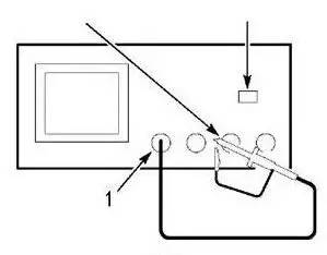
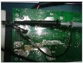
The operation steps for probe compensation adjustment are as follows: 1. Connect the oscilloscope probe to the channel and press the PRESET button on the front panel (in the left panel setting area). Connect the probe signal end and reference ground to the reference output on the oscilloscope panel, and then press Autoset. If using a probe hook front accessory, ensure the signal pin is securely connected to the probe, ensuring a proper connection. As shown in Group Figure 1:
Group Figure 1 Probe Compensation Adjustment
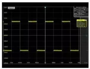
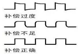
2. Check the shape of the displayed waveform. Possible situations are shown in Figure 2.
Figure 2 Over-compensation, under-compensation, and correct compensation
Both over-compensation and under-compensation need to adjust the probe to ensure better testing of accurate values.
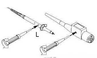
3. If the waveform is incorrect, please adjust the probe as shown in Figure 3 until the waveform matches the correct compensated waveform above.
Figure 3 Probe Compensation Method
The above two points may seem simple, but they are often overlooked by engineers. To make measurements more accurate, please pay attention to inspections. These two calibration functions should be available in any oscilloscope.
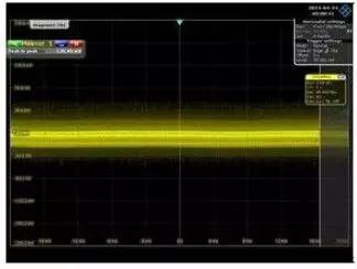
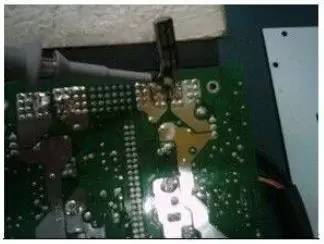
Many power engineers do not pay much attention when measuring ripple, testing based on assumptions. The different usage methods of oscilloscopes lead to significant differences in test results. As shown in Group Figures 4 and 5, for the same product and the same test point, the differences in testing methods lead to significant variations in test results. Ripple is an important parameter for power supplies, but failing tests due to operational issues is not worth the waste of manpower and costs for rectification.
Sometimes your clients may receive erroneous test data due to insufficient attention to the use of instruments. However, your product may be perfectly fine, leading to misunderstandings, causing clients to think they are being deceived. Therefore, testing methods are very important. Paying attention to these details can save a lot of time and enhance your capabilities.
The values tested by oscilloscopes inherently have errors (which I will not explain here for now). Many companies now require the waveform values as a basis for judgment. In fact, oscilloscopes only test the process of voltage changing over time, primarily capturing waveforms during debugging. The specific measurement accuracy of DC voltage effective value is not as accurate as that of digital multimeters. The DC precision indicators of oscilloscopes are calibrated using multimeters as a reference. However, more and more companies and engineers consider the values from oscilloscopes as real values, so we can only try our best to minimize the testing errors.
Below is an illustration and analysis of testing ripple:
The test ripple value of Group Figure 4 is 3.9921V, which is much larger than the 0.126V in Figure 5, but the test value in Group Figure 4 is not real. Problem analysis: In fact, the product has no issues. It is merely a problem with the testing method. Now, let’s point out the issues:
The first error is the use of a long ground wire.
The second error is placing the probe loop and ground wire near the power transformer and switching elements.
The third error is the presence of excess inductance between the oscilloscope probe and output capacitor.
Due to these oversights, a lot of high-frequency signals, transformer magnetic fields, and switching electric fields were picked up, resulting in the oscilloscope displaying waveforms with high-frequency noise mixed in.
The fourth error is using too large a range.
Accurate Ripple Testing Requires:
Using bandwidth limits to measure ripple to prevent picking up non-existent high-frequency noise. Set the oscilloscope bandwidth to 20M. Remove the probe “cap” and ground clip to prevent the long ground wire from forming an antenna effect. Use a short ground wire wrapped between the probe and ground.
Rohde & Schwarz provides dedicated short ground wires. It may be worth considering placing a 0.1uF and a 10uF capacitor in parallel between the signal and ground for decoupling. The length of the capacitor’s PIN legs also affects the test values.