
This article is translated from the “2017 IEEE International Conference on Vehicular Electronics and Safety (ICVES)”
Included paper “Safety Assessment of Automated Vehicle Functions by Simulation-based Fault Injection”
Original authors: Garazi Juez, Estibaliz Amparan
Editor’s Note: When analyzing the concept phase of automotive functional safety based on the existing version of ISO 26262, theoretical methods such as FMEA (Failure Mode and Effects Analysis), FTA (Fault Tree Analysis), and DFA (Dependent Failure Analysis) are often used to analyze failure impacts, thereby deriving safety goals and requirements. However, when facing the complex system of autonomous vehicles, the impact of a failure may not always be foreseeable in advance.
To address this issue, under the premise of known failure types, the authors introduce Fault Injection (FI) simulation experiments as a supplement to the aforementioned safety analysis methods, improving failure impact, safety goals, and safety requirements based on experimental data.
As autonomous vehicles develop, ensuring vehicle safety in the event of a fault becomes increasingly important. This article proposes a simulation-based fault injection method (Sabotage) as a supplement to traditional safety analysis methods in the concept phase of ISO 26262, obtaining failure impacts based on experimental data and refining safety goals and requirements.
Subsequently, this method is applied to the safety analysis of the lateral control system of autonomous vehicles, determining the impact of faults that occur in its model, deriving the Fault Tolerant Time Interval (FTTI) based on maximum lateral error and “steering saturation,” and deriving safety goals and requirements.
* “Steering saturation”: refers to the inability to continue turning when the steering control quantity reaches saturation.
1. Control Architecture of Autonomous Vehicles
This article focuses on functional safety research for Highly Automated Vehicles (HAV). The HAV architecture is primarily divided into lateral and longitudinal control. This research targets the lateral control system, which aims to guide the vehicle along the optimal path and consists of three basic functions:
-
Behavior Planning: Selecting the best path based on vehicle behavior (such as lane keeping, lane changing, or obstacle avoidance);
-
Trajectory Control: Calculating and maintaining the vehicle on the correct trajectory through control algorithms;
-
Steering: Controlling the steering wheel to guide the vehicle along the planned path, with input from the trajectory control module’s calculated correction value.
2. SABOTAGE Framework Based on ISO 26262
1. Framework: SABOTAGE
The existing version of ISO 26262’s concept phase primarily conducts safety assessments through safety analysis methods such as FMEA. Due to the complexity of autonomous vehicle systems, the impact of a specific failure may not be known in advance, leading to incomplete analysis results.
Fault injection provides an effective supplementary method for assessing the safety and controllability of advanced autonomous systems. Under the condition of known failure types, fault injection can determine the impact of a specific failure during system operation and gather related fault data.
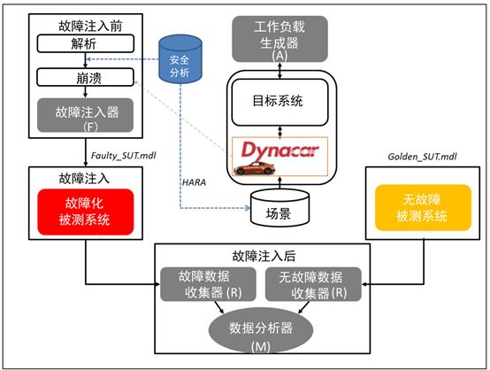
Figure 1: Sabotage: Simulation-Based Fault Injection Framework
Figure 1 illustrates the safety analysis method for autonomous vehicle functions based on fault injection simulation, which can serve as a supplementary means to assess the safety of a certain architecture in the early design phase. By analyzing simulation data, several optimal safety concepts can be weighed and selected.
According to this framework, the general process of the Sabotage method proposed in this study is as follows:
Step 1: Identify Failure Modes. First, the primary functions and their failure types of the relevant items must be known. Then, accurately identify functional failure modes to obtain data about their impacts (at the system/vehicle level). This means that if these failure modes are defined at the system level, their impacts will be reflected at the vehicle level. These faults/failure modes are associated with common fault models stored in a general fault model library (Omission, Frozen, Delay, Invert, Oscillation, Random). These common fault models are pre-defined and are specific fault models for simulating any component/system functional failure modes.
Step 2: Configure Fault Injection Experiments. After conducting a preliminary analysis of the system, fault injection experiments must be configured as part of the workload generator, which includes setting up experiments and driving scenarios, as well as generating a fault list:
-
Objective: Where to inject faults?
-
Fault Model: What is the best fault model representing the functional failure mode?
-
Trigger: How to trigger faults in the system?
-
What are the observation points for fault impacts?
-
How to define the conditions that cause the vehicle to lose its controllability?
For each fault the user wants to inject, it is necessary to clearly specify the fault model involved, target signals (fault localization), fault triggering conditions based on time or path position coordinates (X, Y), and fault duration in the fault list. This information forms the basis for generating the fault injector (Saboteur). The fault injector is a component added to the system behavior model for fault injection. A fault is injected for each target signal generated.
The configuration of the experiments includes the selection of the vehicle and the definition of operational situations:
-
Location: Highway, city;
-
Road conditions: Uphill, curves;
-
Environmental conditions: Good, heavy rain;
-
Traffic conditions: Smooth;
-
Vehicle speed;
-
Behavior: Stop, overtake, lane keeping;
-
Potential risk participants: Driver, passenger, pedestrian;
The experimental scenarios are selected by the scenario configurator based on the previously defined operational situations, choosing the best driving scenarios from the scenario directory to load into the Dynacar platform (a real-time vehicle dynamics simulation system).
Step 3: Create Faulty System Under Test. To do this, the fault injector module creates fault generator code based on the information from the fault list and general fault model templates. This process can be automated based on the data from the library and lists.
Step 4: Compare the simulation results of the faulty system under test with those of the fault-free system to analyze the fault impacts, thus deriving appropriate safety goals and requirements.
2. Using Sabotage in the Concept Phase of ISO 26262
The Sabotage method mentioned in the previous section can be applied in the concept phase of ISO 26262. Under the premise of known functions and fault types of the relevant items, the impacts of a certain fault can be obtained through fault injection simulation in the hazard analysis and risk assessment process, refining safety goals accordingly, and deriving safety requirements in the functional safety concept process. Its specific applications include:
-
Identifying hazards through fault injection rather than safety analysis methods like FMEA. The hazards can be visually observed in the Dynacar virtual environment (for example, when the vehicle fails to turn when it should).
-
Refining safety goals based on simulation results and hazard identification.
-
Determining FTTI and safety states. As shown in Figure 2, FTTI is the time from when a fault is injected to when a hazard occurs. For advanced autonomous driving systems, FTTI determines the required fault tolerance level (such as redundancy, functional degradation) to prevent the vehicle from losing control.
-
Comparing the simulation results of fault-free and faulty systems, safety requirements can be derived from the maximum differences between the two simulations.
-
Based on previous results, safety requirements will be integrated into the functional safety concept.
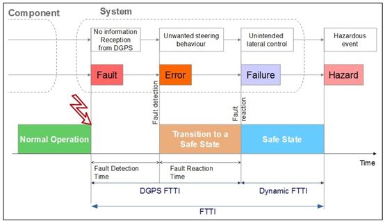
Figure 2: Fault-Error-Failure Chain and Definition of FTTI
3. Safety Assessment of the Lateral Control System
This section presents an example of applying Sabotage to the safety assessment of the existing lateral control system (which is part of the lane-keeping function of advanced autonomous vehicles) based on the concept phase of ISO 26262. Since this model lacks appropriate safety mechanisms, analyzing the FI simulation results can address the following issues:
-
Obtaining impact data of specific faults at the vehicle and relevant item levels based on fault injection simulation results.
-
Completing safety analysis: determining safety goals (including FTTI values and safety states), functional safety requirements, and safety concepts.
The following is the analysis process and results of this study in the ISO 26262 concept phase:
1. Definition of Relevant Items
As mentioned in Chapter 2, the application premise of the method proposed in this article is to clarify the functions and fault types of relevant items in the definition process of ISO 26262: The lateral control relevant items can be decomposed into multiple functions and sub-functions, with faults including: steering (Omission, Commission), trajectory control (Omission or Commission), and behavior planner (unnecessary local planning, unnecessary perception, unnecessary decision-making).
2. Hazard Analysis and Risk Assessment
The FI simulation results can serve as a supplementary method outside of traditional safety analysis methods for hazard identification and obtaining safety goals (primarily based on FTTI values).
The FI simulation experiment conducted in this study involved a vehicle traveling at a constant speed of 45km/h with the lane-keeping function enabled in a smoothly flowing urban environment. When the vehicle was navigating a curve, a fault would be triggered, recreating functional failure modes related to differential GPS (DGPS) and the steering system. The fault list set up for the experiment is shown in Table 1.
Table 1: Example of Fault List
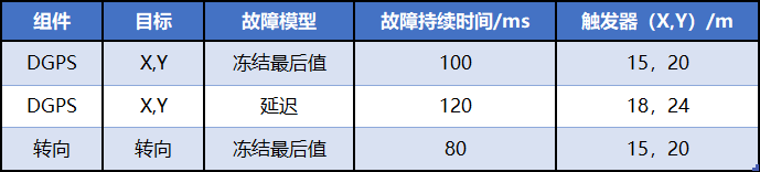
This table is only a partial example of the fault list in this study, and thus does not correspond one-to-one with Table 2.
According to the steps in Chapter 2, the fault generator automatically injects faults based on the previously established fault list. To ensure the faults have the most severe impact, these faults are triggered at several curve points to achieve the most serious effects. Since the main goal of our simulation is to calculate the FTTI value of lateral control, the observed signals are lateral error and steering saturation. Figure 3 illustrates the calculation principle of the steering control’s FTTI.
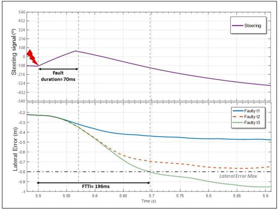
Figure 3: Calculation Principle of FTTI
The maximum lateral error, defined using the following formula, serves as the standard for system loss of control:
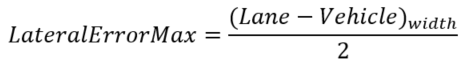
Table 2 describes the hazard identification information obtained from the FI simulation results. By modeling failures at different relevant item levels using general fault models, we can measure their impacts at the vehicle level and the resulting hazardous behaviors.
Table 2: Impact of Failures at Vehicle Level
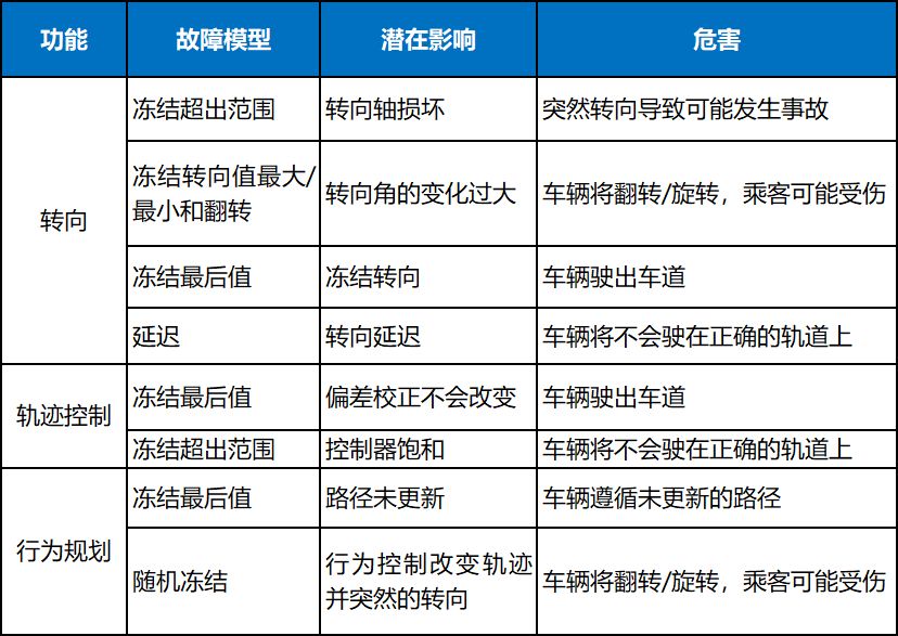
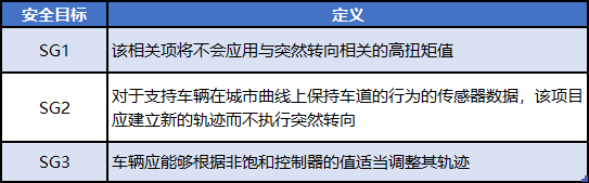
Based on Table 2 and simulation test data, partial results of hazard analysis and risk assessment can be analyzed, as shown in Table 3, which includes the FTTI values of the most severe failure modes for specific functions (represented as fault models) calculated based on Figures 2 and 3. The fault duration is the time taken to handle the fault appropriately (transition to a safe state). For example, a fault related to the trajectory controller can exist in the system for 400ms before a hazard event occurs: 240ms for detection and response, and 160ms to control the fault, thus ensuring safety goals are not violated. The specific definitions of safety goals in Table 3 are shown in Table 4.
Table 3: Hazard Analysis and Risk Assessment
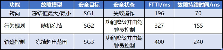
Table 4: Safety Goals
3. Functional Safety Concept
Based on the safety goals obtained from the previous process and combined with FI simulation results, functional safety requirements are derived, as shown in Table 5. The formula for calculating the maximum lateral error is as follows:
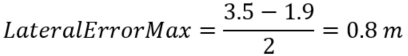
Table 5: Safety Requirements
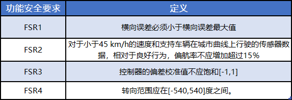
Thus, functional safety requirements are derived from simulation data rather than traditional dependent failure analysis (DFA). The main conclusion is that the current lateral control design cannot ensure the system is unaffected by disturbances, hence the architecture needs to be redesigned to ensure this attribute, meaning the steering system should be redundant to achieve the required availability level. Specifically, based on the data in Table 3, to prevent dangerous occurrences, faults related to steering functions must be controlled within 196ms. If the vehicle flips or rotates, passengers may be injured, so the steering function must be available within 70ms. Regarding failures related to behavior planning, such as failures caused by DGPS faults, the reaction time is 155ms, thus appropriate functional degradation may be necessary. Finally, different functions must be correctly partitioned to avoid cascading failures.
4. Conclusion
The above introduces a simulation-based fault injection method to assess the safety of automated vehicle functions. This method is applied to the case of urban vehicles embedded with automatic lateral control functions. This article focuses on determining the FTTI values of permanent faults based on maximum lateral error and steering saturation. A major advantage of the proposed method is that it can serve as a supplementary safety analysis method, achieving an ISO 26262-compliant safety assessment process.
-END-
Article Selection
Entrepreneurs
Elon Musk and Jia Yueting | Ford CEO Resigns | Hozon Auto’s Yang Rong
Ren Zhengfei Layoffs|Battery Giant Kyle Leaves Tesla
Intelligent Driving
BBC Autonomous Driving Documentary
Why Baidu Apollo is said to be a failed imitation of a tiger
Overview of Onboard Radar Communication Systems
Challenges and Opportunities in Surveying and Positioning Services in the Intelligent Era
New Energy Vehicles
National Overview of 50 New Energy Vehicle Projects
Trends in Lithium Battery Development|China’s Electric Vehicle Industry Electrification Process
Apple Acquires Tesla?|Toyota and Tesla Break Up
Overview and Outlook of Subsidies for New Energy Passenger Vehicles
Current Status and Trend Analysis of New Energy Vehicle Drive Motors
Projects and Reviews
Top 10 Autonomous Driving Startups in Israel
Overview of 37 Automotive Car Sharing Projects|Baidu Invests in NIO
Pony.ai, a Baidu-Backed Autonomous Driving Startup’s Path to Breakthrough
These experts left Google to start five (with varying fates) autonomous vehicle companies
Understanding High-Precision Driving Positioning Technology Without Basic Knowledge
Hao
Shi
Auto
Vehicle
Connecting Capital and Industry for You
New Energy Vehicles Autonomous Driving Vehicle Networking
Contact Email

ClickRead the Original Article to view the article “Autonomous Vehicles as a ‘Scientific Experiment’“