“Fault injection” is a concept often heard in the HIL community. What exactly is it? Where did it come from? What is its historical background? What does the future hold for it?
Let’s start by casually looking for a couple of advertisement images online:
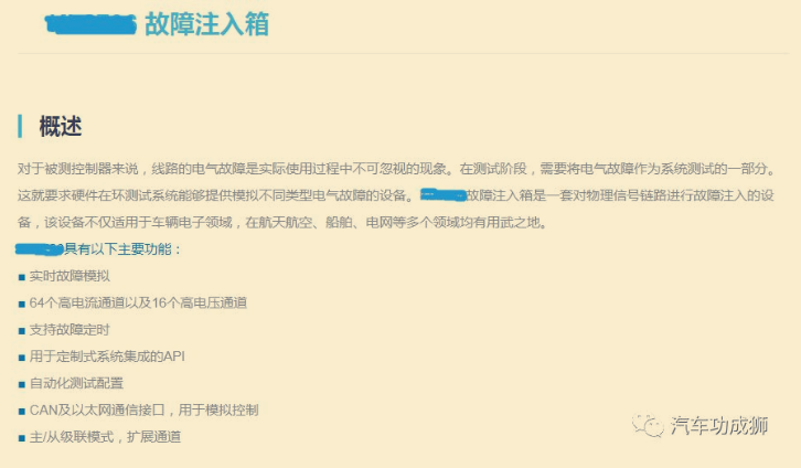
It’s a bit convoluted and not very easy to understand, not something for the general public, right?
That’s correct; perhaps their goal is to make you feel it’s impressive yet incomprehensible, shrouded in mystery, leaving you unsure of how to proceed.
Let’s use two images to explain the difference between having and not having a “fault injection box”.
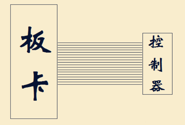
Image 1: Without a fault injection box
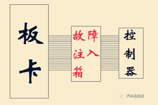
Image 2: With a fault injection box
In Image 1, without a fault injection box, the signals from the PCB connect directly to the controller being tested, with no intermediary devices.
What are the shortcomings of this approach? According to some manufacturers, it can only simulate “normal signals” and cannot emulate extreme conditions.
For example, in the event of a crash, if the VCU’s wiring harness is broken or short-circuited, or if any wire connects to high voltage…The fault injection box mainly simulates these situations.
This primarily tests the VCU’s survivability and operational status under extreme conditions.
For instance, in a car chase movie, if a car with a protagonist’s aura loses part of its rear, has flat tires, and a crumpled front, yet remains vigorous and unstoppable, it likely means that the “fault injection testing” was done thoroughly  .
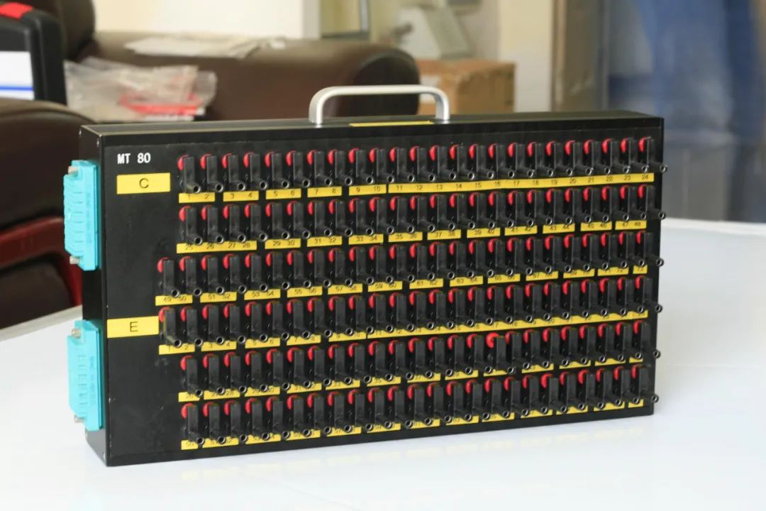
We can use the fault injection box to connect any two or more wires together, or disconnect any wire to simulate various extreme fault scenarios and observe the VCU’s response.
To simulate the corresponding wiring harness anomalies, how should we control the fault injection box?
Generally, this is done via control software provided by the manufacturer, and more advanced vendors can automate testing to control it.
Fault injection boxes can be external or internal. Internal ones are directly installed in the HIL cabinet, while external ones are connected in series between the HIL and the wiring harness of the object being tested.
.
We can use the fault injection box to connect any two or more wires together, or disconnect any wire to simulate various extreme fault scenarios and observe the VCU’s response.
To simulate the corresponding wiring harness anomalies, how should we control the fault injection box?
Generally, this is done via control software provided by the manufacturer, and more advanced vendors can automate testing to control it.
Fault injection boxes can be external or internal. Internal ones are directly installed in the HIL cabinet, while external ones are connected in series between the HIL and the wiring harness of the object being tested.
No Fault Injection
External Fault Injection Box
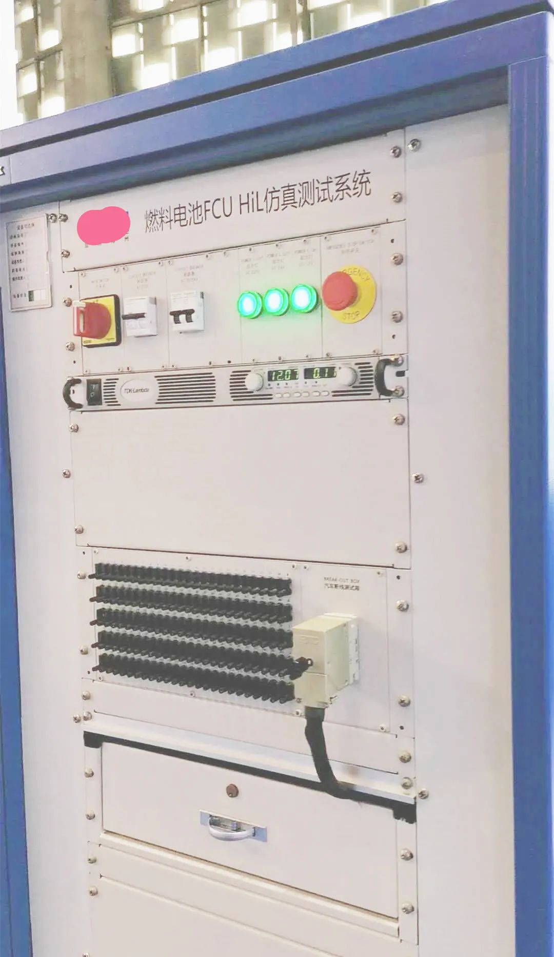
Internal Fault Injection Box
External ones are more flexible but require more user intervention; internal ones are closed and fully prepared, which benefits the suppliers. If you want to make modifications, the supplier may say, “No modifications allowed  ; you have to pay for us to help you modify it
 “.
Fault injection is just that; the technology level is average, and its necessity is relatively low. It operates through a device called a “fault injection box” by controlling the internal switch combinations to short-circuit wires and perform similar operations.
In China, although the core technology of HIL equipment is monopolized by foreign countries, many HIL integrators can independently develop such devices due to the low threshold of fault injection boxes, resulting in average added value.
“.
Fault injection is just that; the technology level is average, and its necessity is relatively low. It operates through a device called a “fault injection box” by controlling the internal switch combinations to short-circuit wires and perform similar operations.
In China, although the core technology of HIL equipment is monopolized by foreign countries, many HIL integrators can independently develop such devices due to the low threshold of fault injection boxes, resulting in average added value.
Point-by-Point Commentary
First, fault injection is a product of the mechanical era,full of the flavor of internal combustion engines.
If the wires of the electronic control module are short-circuited or broken, should it not stop? Should it continue to work?Do you think I’m a hand-pushed tractor?
Second, private cars are not meant for filming movies; they don’t need to be wrecked and still operate like nothing happened. Therefore, the author believes that some extreme faults are essentially unsolvable.
For instance, if a certain high-speed digital signal short-circuits with the power supply, the VCU cannot distinguish whether it is short-circuited with the power supply or the signal is valid; if a certain high-speed digital signal line is broken, the VCU similarly cannot distinguish whether the line is broken or the signal is invalid.
Thus, the VCU should simply perform its functions; if a critical wiring harness is broken or short-circuited, it should enter the normal fault handling process, reducing power or stopping as necessary.
Third, in the current automotive electronic control development process, basic wiring harness fault simulation is meaningful, but there is no need to invest too much energy in “fault injection”; a significant portion of “faults” can be handled by the VCU according to its normal functional logic.
The truth is, for many users, the fault injection box is rarely used for fault injection; it is mostly used for signal interception and reading.Fault injection is purely a signal interception device made for the convenience of manual testing in HIL, a compromise measure for unsatisfactory automated testing!
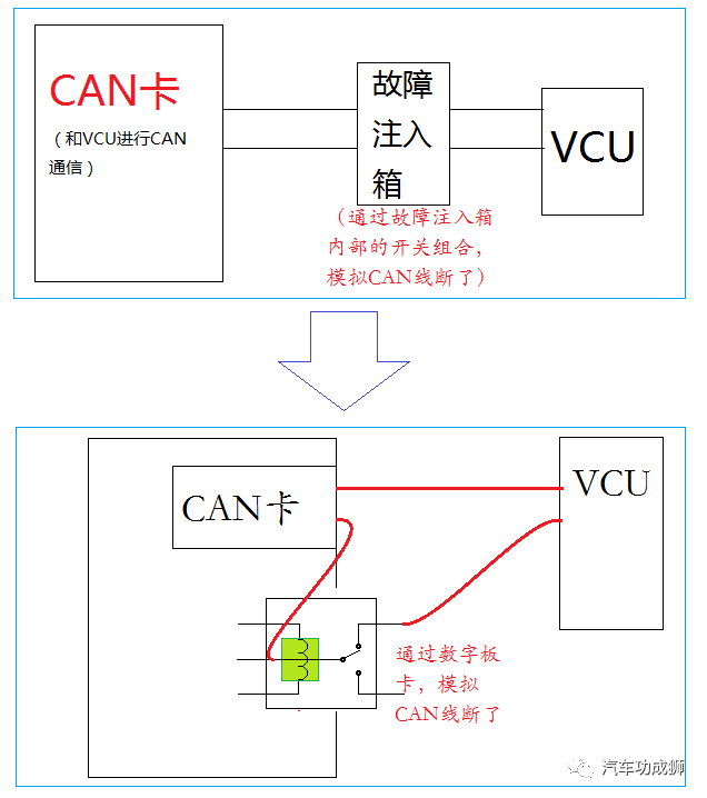
In fact, faults can also be simulated through a relay matrix board, as shown below:
Relay Digital Signal Board Replacing Fault Injection Box
Another concept in the HIL field, similar to fault injection, is called “signal conditioning”.
Signal conditioning is purely a hardware matter without a control interface; its function is to convert the signals from the PCB into signals that the VCU can accept.
For example, converting a 5V digital signal into a 12V digital signal, or converting a -5~5V analog voltage into a 0~10V voltage, and so on.
This conversion is also a typical historical legacy product, primarily found in NI platform HIL, which is a phenomenon unique to the NI platform.
Because most of NI’s boards operate at 5V and 3.3V voltage standards, lacking 12V or 24V, they cannot be directly applied in HIL testing and require signal conversion.
This fully exposes that NI is an amateur in HIL 

 , being a latecomer, a half-hearted player. Its boards are not designed for the automotive industry, requiring additional signal conditioning boards to be usable.
However, this “conditioning” is not necessarily a bad thing for NI:
-
First, its boards (with slight conditioning) can be used in aerospace, automotive, industrial, bio-chemical, shipbuilding, and many other industries, offering strong versatility and low shared costs.
-
Second, this “conditioning board” is not too technically challenging, allowing its integrators to handle it, leaving some benefits for them, which can unite more partners and better practice the strategy of “surrounding the city from the countryside”.
However, we must understand that for dSPACE, signal conditioning is completely unnecessary; its boards are designed for the automotive industry, directly supporting 12V and 24V, able to connect directly to the controller being tested without needing intermediate conditioning.
To compensate for the lack of “professionalism” and compete with dSPACE, NI has come up with a big move: open source!
For example, the CustomDevice in NI platform HIL is an important means for NI to rally various small players to collectively compete against dSPACE.
Through CustomDevice, various third-party boards can be used in NI platform HIL, even those with no brand purchased from online shops.
|
Internal Communication Group
|
We welcome everyone to join our internal WeChat group where industry experts and business users gather. Finding clients, suppliers, and discussing solutions is very convenient.
|
|
Source Code Sharing
|
Free access to HIL automation testing source code based on Excel, Excel2DBC source code, and bus testing source code is available. For details, please refer to the main menu.
|
|
Product Research and Promotion
|
Manufacturers with original core technologies are welcome to contact us to provide opportunities for us to learn about your products and showcase them to more engineers, helping the industry rise!
|