Originally, we planned to discuss the creation of the electrical schematic today, but considering that using CAD Electrical or EPLAN would take too long, we decided to create a dedicated series for drawing schematics later. Today, we will skip drawing the electrical schematic and focus on designing the entire equipment’s action flowchart as a preliminary preparation for programming.1. Equipment Action FlowchartThe automatic actions are mainly divided into four major modules: Loading –> Testing –> Sorting –> Discharging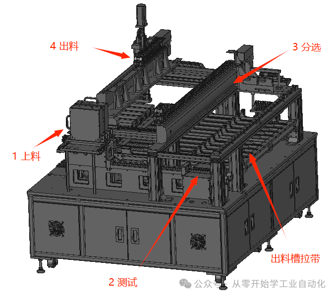 Main Flowchart:After powering on, the system first initializes, and upon completion, simultaneously starts the four major modules, which will have corresponding signal connections between them.
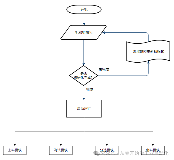 Module Interaction:1. When the testing module is idle, it sends a signal to the loading module to allow loading. The loading module begins loading and notifies the testing module when loading is complete.2. When the sorting module is idle, it sends a signal to the testing module to allow the feeding signal to rise. The testing module waits for the test to complete, and the testing cylinder rises to feed.
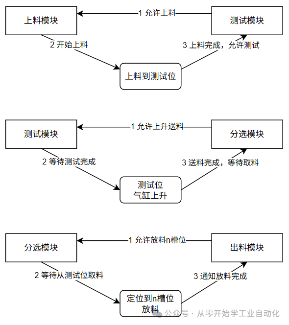 Loading Module Flowchart:Manual loading –> Rotating loading –> Scanning code –> Material sensing count –> Testing sensing count –> Output allow testing signal.
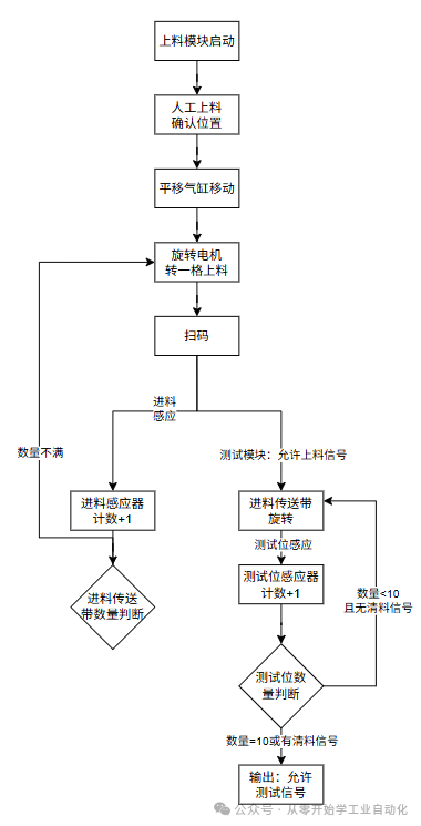 Testing Module Flowchart:Full quantity or clear material signal –> Start testing –> Testing complete –> Cylinder rises waiting for the robotic arm to pick up material –> Material pick up complete –> Cylinder descends.
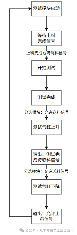 Sorting Module Flowchart:Waiting for the testing module to send the material pick-up signal –> Positioning the pick-up location –> Descending to pick up material and then rising –> Output allow feeding signal –> Positioning to n slots based on the upper computer’s classification.
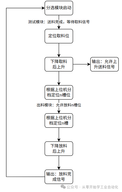 Discharging Module Flowchart:Sorting conveyor belt rotates –> Position sensor detects no material, allows discharging –> Modify the allowed discharging slot signal –> Upon receiving a certain allowed discharging slot from the sorting module, discharging is complete –> Modify that slot to not allow discharging –> The discharging robotic arm determines which slot can pick up material based on the sensor –> Robotic arm picks up material –> Discharges into the battery box.
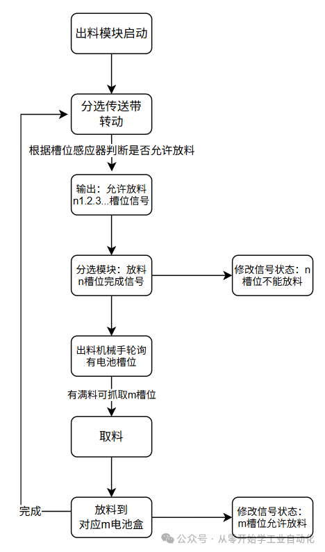 2. Precautions
- The programs for the four major modules are written separately.
- Signal interaction between modules; modifications and debugging of one module should reduce the workload of modifications.
- Interaction with the upper computer for scanning codes and testing signals requires detailed definitions.
3. Summary The main goal is to understand the action logic of the entire equipment, then subdivide each module and write the action logic separately. When writing the PLC program, it should be done by module. The alarm module, manual operation module, parameter initialization module, and initialization action module are not included here as they are relatively simple; we will discuss them in detail when we actually write the PLC.Download for free: Send “3011” or “18650” to the public account to download related materials.There are many related articles in the public account,If you like it, please follow or share it, thank you for your support..A WeChat technical exchange group has been established, everyone can add it in the public account menu, and you are welcome to exchange and learn together.C# Beginner’s Special – Detailed Explanation of How to Use C# Winform to Develop a Mitsubishi FX3U PLC Communication Simulator (Final Chapter)Beginner Project [Automatic Screw Machine] C#, PLC, Touch Screen Practical (3/5): PLC Program Design