Teaching Objectives
1. Understand and distinguish the concepts of clock cycle, machine cycle, and instruction cycle, which are the foundation of all timing control.
2. Understand timers; the essence of a timer is a counter, and the source of its counting pulses determines its operating mode (timer mode or counter mode).
3. Understand how timer overflow triggers interrupt requests and be able to configure registers related to the timer.
4. Understand and be able to configure the four operating modes of the timer.
Delay Control and Timers
In the technical system of the 51 microcontroller, delay control and timer applications constitute the core module of embedded development, as important as the basic toolbox for electronic engineers. From precise timing control to complex system scheduling, these two technical elements together form the foundation for implementing various intelligent control functions. Whether achieving the breathing light effect of an LED, precise angle control of a stepper motor, or building a real-time data acquisition system, they all rely on the precise calculation of delay parameters and the reasonable configuration of timer resources.
To achieve these precise controls, one must first deeply understand the most basic time measurement units of the microcontroller—clock cycles, machine cycles, and instruction cycles. These concepts are like the atoms that build the time system, collectively defining the basic rhythm of the microcontroller’s operation.
Clock Cycle, Machine Cycle, and Instruction Cycle
During the operation of a microcontroller, there are three important time concepts: clock cycle, machine cycle, and instruction cycle. Understanding the relationship between them is crucial for mastering the principles of delay and timers.
The clock cycle, also known as the oscillation cycle, is the most basic time unit in the microcontroller (also referred to as the microcontroller’s main frequency), determined by the frequency of the external crystal oscillator. When using a 12MHz crystal oscillator, the clock cycle is 1/12MHz, approximately 0.083 microseconds. One can think of the clock cycle as the “heartbeat” of the microcontroller, with each beat providing a basic time pulse for its operation.
The machine cycle is the time required for the microcontroller to complete a basic operation, consisting of 12 clock cycles. In other words, under a 12MHz crystal oscillator, the time for one machine cycle is 12×(1/12MHz)=1 microsecond. Within one machine cycle, the CPU can complete an independent operation, such as reading an instruction from memory or performing a simple calculation on data. The machine cycle can be viewed as the basic time unit required for the microcontroller to complete a small task.
The instruction cycle is the time required to execute an instruction, measured in machine cycles. Different instructions require different numbers of instruction cycles, depending on their complexity. For example, some simple instructions, such as transferring data from one register to another (MOV instruction), can be completed in just 1 machine cycle; while more complex instructions, such as multiplication (MUL) and division (DIV), require 4 machine cycles to complete. The instruction cycle is like the time required to complete a full work task, with different tasks (instructions) taking varying amounts of time (instruction cycles) due to their complexity.
Because of the close relationship between instruction cycles and machine cycles, and the differences in instruction cycles for different instructions, the delay functions we wrote in previous experiments based on microseconds and milliseconds (also known as software delays) essentially achieve time control by executing a series of instructions in a loop, utilizing the accumulation of instruction cycles to implement timing control—these functions assume the microcontroller operates at 12MHz, estimating the total instruction cycles within the loop to roughly calculate the delay time. However, this method of delay, which relies on counting instruction cycles, has certain limitations:
On one hand, the differences in instruction cycles for different instructions within the loop can lead to fluctuations in actual execution efficiency, thereby reducing delay accuracy; on the other hand, the duration of instruction cycles is determined by machine cycles, which in turn depend on the crystal oscillator frequency (for example, a 12MHz crystal corresponds to a 1μs machine cycle). Once the microcontroller’s main frequency changes (for instance, switching to a 6MHz crystal), both machine cycles and instruction cycles will change accordingly, rendering the original loop parameters completely ineffective, necessitating a recalculation of instruction sequences and loop counts, lacking universality across different main frequency environments.
While software delays can meet basic functional verification needs, their precision defects and lack of universality will be magnified in industrial applications with stringent timing accuracy requirements (such as sensor data acquisition and precise motor speed control), making it difficult to meet the timing control standards required in practical applications.
Therefore, in scenarios requiring precise timing control, a more reliable technical solution must be adopted—precise delays need to be achieved through timer interrupts. Timer interrupts rely on hardware counting logic, using machine cycles as a fixed timing unit, unaffected by fluctuations in instruction execution efficiency, and can be adapted to different main frequency environments simply through register configuration, fundamentally solving the precision and universality issues of software delays, making it a core technical means for timing control in industrial-grade microcontrollers.
Timer Interrupts
As the name suggests, timer interrupts send interrupt requests at specified times. How does the microcontroller calculate time to achieve timer interrupts?
The core of the timer is an adder counter. When we start the timer, it will perform an accumulation operation on the current count value at the end of each machine cycle. Taking a common 12MHz crystal oscillator as an example, at this point, one machine cycle is 1 microsecond, meaning that for every 1 microsecond that passes, the counter’s value will automatically increment by 1.
It is important to note that the trigger condition for timer interrupts is not “the count value reaches a preset initial value,” but rather that the counter accumulates from the initial value until it reaches the maximum value and overflows: when the counter accumulates to its maximum count (for example, the maximum count value for a 16-bit timer is 65535), it will automatically reset to zero and trigger an overflow. At this point, the hardware will reload the preset initial count value based on the configuration (if the auto-reload function is enabled) and set the corresponding interrupt flag (such as TF0, TF1) to notify the CPU that a predetermined timing cycle has been completed.
If we want to achieve a 10-millisecond delay, we need to first calculate the initial count value for the timer based on the machine cycle and the target delay time: for a 12MHz crystal oscillator (1 microsecond/machine cycle), 10 milliseconds requires a total of 10000 machine cycles. Since the maximum count value for a 16-bit timer is 65535, the initial count value should be set to “65535 – 10000 + 1 = 55536” (+1 is because the counter starts from the initial value, and after accumulating 10000 times, it will reach 65535 and overflow). After writing this initial value into the timer’s high and low registers (such as TH0, TL0), we start the timer: the counter will start from 55536, incrementing by 1 every 1 microsecond, and when it accumulates to 65535, it will overflow, precisely corresponding to a 10-millisecond delay, while triggering an interrupt to notify the CPU.
The 51 microcontroller has two 16-bit programmable timers, T0 and T1, each consisting of high 8-bit and low 8-bit registers. TL0 is the low 8-bit register for T0, TH0 is the high 8-bit register for T0, TL1 is the low 8-bit register for T1, and TH1 is the high 8-bit register for T1.
The main function of T0 and T1 is counting. After powering on or resetting the microcontroller, both T0 and T1 are initialized to zero. Once the microcontroller sets the timer function, T0 and T1 will automatically start counting under the influence of the crystal oscillator. When T0 or T1 overflows, a specific circuit generates an internal interrupt, sending a timer interrupt request to the microcontroller, and T0 or T1 will automatically reset to zero.
The operation of counting by T0 and T1 requires one machine cycle. Assuming the microcontroller’s clock cycle (crystal frequency) is 12MHz, 12 clock cycles equal one machine cycle, and the time for one machine cycle is 1μs (microsecond). Therefore, to count T0 or T1 to the maximum, it requires 2^16-1 counts, which is 65536μs, approximately 65.5ms.
If we want the timer to send an interrupt request every 50ms, we need to give T0 or T1 an initial value, which is the difference between 65536μs and 50000μs. After counting an additional 50000 counts from the initial value, T0 or T1 will overflow and send an interrupt request, which corresponds exactly to 50ms. After T0 and T1 reset to zero, we assign the initial value to T0 and T1 again, preparing for the next interrupt request.
The internal structure of the timer is shown in the figure below:
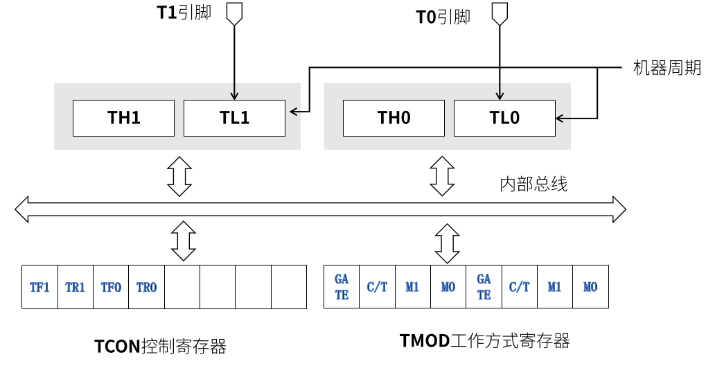
TH1 and TL1 are the high and low registers for T1, while TH0 and TL0 are the high and low registers for T0, each register being 8 bits long. Under the influence of the machine cycle, counting starts from the low register. When the low register is full, it increments the high register by one, until the high register is also full, at which point T0 or T1 overflows, setting the TF0 or TF1 bit in the TCON control register to 1 and sending a timer interrupt request.
TF0 in the TCON control register is the overflow flag for the T0 timer count, and TF1 is the overflow flag for the T1 timer count. When the timer count overflows, the hardware sets the TF0 or TF1 bit to 1 and sends an interrupt request. After entering the interrupt service routine, the hardware automatically clears the TF0 or TF1 bit.
TR1 and TR0 are the control bits for the operation of timers T1 and T0, respectively. TR1 and TR0, along with the GATE bit of the TMOD working mode register, jointly control the start and stop of the timer. If the GATE bit is zero, the start and stop of timers T1 and T0 are solely controlled by TR1 and TR0. When TR1 and TR0 are both 1, timers T1 and T0 start; when TR1 and TR0 are both 0, timers T1 and T0 stop. If the GATE bit is 1, the start and stop of timers T1 and T0 are controlled by TR1 and TR0 and the level state on the external interrupt pins (INT0 and INT1).
The memory address of the TCON register is 88H, and the bit addresses (from low to high) are 88H~8FH, allowing for bit addressing; the memory address of the TMOD register is 89H, which can only be byte-addressed and not bit-addressed.
Some students may wonder whether the memory addresses of the TCON register and TMOD register will conflict. First, it is confirmed that the memory addresses of the TCON register and TMOD register do not conflict. The TCON register is a bit-addressable register, located in a separate memory space in the 51 microcontroller, with each bit having its own memory address. The address of the TCON register at 88H contains 8 addressable bits, namely 88.0~88.7, where 88.0 corresponds to 88H, 88.1 corresponds to 89H, and so on. Therefore, the memory addresses of the TCON register and TMOD register do not conflict.
In practical applications, timers need to meet different timing or counting requirements: for example, millisecond-level LED blinking timing, second-level digital tube display refresh, or counting statistics of external pulse signals. Different requirements have varying demands on the counting range, reloading method, and resource usage of the timer. Relying solely on fixed counting logic cannot adapt to all scenarios, which necessitates setting the working mode of the timer to flexibly adjust its counting structure, reloading mechanism, and functional characteristics to match diverse application needs.
Timer Working Modes
The timer working modes of the 51 microcontroller mainly include the following four, applicable to T0 and T1 timers.
1. Mode 0 (13-bit Timer/Counter)
The counter width is 13 bits (TL0/TH0 low 5 bits + high 8 bits), with a maximum count value of 8191. Suitable for short-term timing or low-frequency counting scenarios, requiring manual reloading of the initial value.
2. Mode 1 (16-bit Timer/Counter, Most Common)
16-bit counter (TL0 + TH0), with a maximum count value of 65535. Requires manual reloading of the initial value in the interrupt service routine, suitable for medium precision timing (e.g., 50ms interrupts).
3. Mode 2 (8-bit Auto-Reload Mode)
8-bit counter (TL0) and 8-bit auto-reload register (TH0), automatically reloads the initial value from TH0 upon overflow. Suitable for high-frequency timing (e.g., PWM generation), requiring no manual intervention.
4. Mode 3 (Dual 8-bit Counters, Only T0 Supported)
Splits T0 into two 8-bit counters (TL0 and TH0), with T1 stopped. Suitable for scenarios requiring independent control of two timing tasks.
Method for Configuring Working Modes
The C/T bit of the TMOD register is used to set the working mode of the timer: when C/T is 1, the timer operates in counter mode; when C/T is 0, the timer operates in timer mode.
C/T=0 (Timer Mode): Counts the internal system clock (machine cycle) for time measurement;
C/T=1 (Counter Mode): Counts the pulse signals on external pins (T0/T1) for event statistics.
The M1 and M0 bits are used to set the length of the timer working bits. When both M1 and M0 are zero, the timer working bit length is 13 bits; when M1 is zero and M0 is one, the timer working bit length is 16 bits. The high four bits of the TMOD register control T1, while the low four bits control T0.
Implementing Precise Delay Functions
Assuming the microcontroller’s clock cycle is 12MHz, using the T0 timer for counting. The timer uses one machine cycle for each count, and the counter requires 65536 counts to be full, approximately 65536μs, meaning the timer sends a timer interrupt request every 65536μs (about 65.5ms). In the program, we can set an interrupt count variable num, initialized to 0, and in the interrupt handler, increment num by 1. When num is greater than or equal to 1000/65.5, it can be considered as 1 second, and then num is re-initialized to zero for the next count.
Considering that 65.5ms is inconvenient for calculations, we can set the timer to send a timer interrupt request every 50ms. When num counts to 20, it corresponds exactly to 1 second. If we need the timer to send an interrupt request every 50ms, we need to assign an initial value to T0, which is the difference between 65536μs and 50000μs, 15536μs. T0 consists of two 8-bit registers, TH0 and TL0, where TH0 stores the high 8 bits of 15536, and TL0 stores the low 8 bits.
The delay function code is as follows:
unsigned char num; // Interrupt count variable// Delay 1 second functionvoid delay_1s() { num = 0; // Reset counter TMOD &= 0xF0; // Clear T0 configuration TMOD |= 0x01; // Configure T0 timer mode, working mode is mode 1 (16-bit timer) TH0 = (15536 >> 8) & 0xFF; // Load high 8 bits of initial value TL0 = 15536 & 0xFF; // Load low 8 bits of initial value ET0 = 1; // Enable T0 interrupt EA = 1; // Enable global interrupt TR0 = 1; // Start T0 timer while(num < 20); // Wait for count to reach 20 (50ms*20=1 second) TR0 = 0; // Stop timer ET0 = 0; // Disable T0 interrupt} // T0 interrupt service routinevoid t0() interrupt 1 { TH0 = (15536 >> 8) & 0xFF;// Reload high 8 bits of initial value TL0 = 15536 & 0xFF; // Reload low 8 bits of initial value num++; // Increment interrupt count}t0() is the interrupt handler for timer T0. In the interrupt handler, we need to reload TH0 and TL0 with the initial value each time and increment the interrupt count variable num. It is important to note that avoid writing too many processing statements in the timer interrupt handler, as if the processing statements are too many, the current interrupt handler may not finish executing before the next interrupt occurs, leading to the loss of that interrupt. Therefore, any functionality that can be completed in the main program should not be placed in the interrupt handler, and the code in the interrupt handler should remain concise and efficient.
Timer Interrupt Experiment
1. Experiment Objectives
(1) Master the working mode and initialization configuration method of timer T0.
(2) Understand the triggering mechanism of timer interrupts and the specifications for writing interrupt service routines.
(3) Implement timer interrupt control for external devices (such as LED blinking).
2. Hardware Requirements
The electronic components for the circuit are listed in the table below:
|
Component Name |
Model |
Search Term |
Setting Value |
|
51 Microcontroller |
AT89C52 |
AT89C52 |
/ |
|
LED |
/ |
LED-RED |
/ |
|
Resistor |
/ |
RES |
220 Ohm |
|
Power Supply |
POWER |
/ |
5V |
|
Ground |
GROUND |
/ |
/ |
|
Crystal Oscillator |
/ |
CRYSTAL |
12MHz |
|
Capacitor |
/ |
CAP |
22pF |
3. Circuit Connection Scheme
(1) The timer T0 pin (P3.4/T0) does not require additional wiring (interrupt triggering relies on internal counting).
(2) The anode of the LED connects to the 5V power supply, and the cathode connects to pin P1.0 through a 220Ω resistor.
(3) The two ends of the crystal oscillator connect to XTAL1 (pin 19) and XTAL2 (pin 18), each in series with a 22pF capacitor to ground.
Reference Circuit:
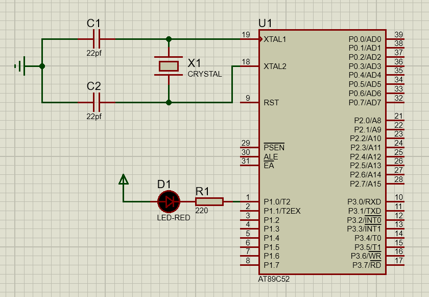
The crystal oscillator circuit mainly provides clock pulse signals (the clock cycle of the microcontroller) for the microcontroller. In the Proteus simulation, the simulated AT89C52 microcontroller provides clock pulse signals through an internal RC oscillator, but with lower precision (approximately ±1% error), suitable for scenarios with less stringent timing requirements. When timing accuracy is not critical, an external crystal oscillator circuit is not necessary. However, if precise timing is required using timer interrupts, an external crystal oscillator (typical frequencies of 11.0592MHz or 12MHz) must be used to ensure clock stability.
4. Experiment Principle Analysis
Timer T0 Working Mode 1 (16-bit Timer)
(1) Counting Structure: Composed of TH0 (high 8 bits) and TL0 (low 8 bits), forming a 16-bit counter with a counting range of 0~65535.
(2) Counting Clock: Obtained by dividing the microcontroller’s crystal oscillator frequency, machine cycle = 12 / crystal frequency (for a 12MHz crystal, machine cycle = 1μs).
(3) Timer Time Calculation
Timer Time = (65536 – Initial Value) × Machine Cycle.
Example: Under a 12MHz crystal, to time 50ms, the initial value should be set:
50ms = (65536 – X) × 1μs → X = 65536 – 50000 = 15536 (Hexadecimal: 0x3CB0), thus TH0=0x3C, TL0=0xB0
Timer Interrupt Control Logic
(1) Interrupt Enable Configuration: Global interrupt (EA=1) and T0 interrupt (ET0=1) must be enabled.
(2) Interrupt Trigger Condition: T0 counter overflows (counts from the initial value to 0xFFFF), hardware automatically sets TF0 (T0 overflow flag) to trigger the interrupt.
Interrupt Service Process
(1) After responding to the interrupt, the hardware automatically clears the TF0 flag (only in mode 1, no manual clearing is needed).
(2) Enter the interrupt service function (void Timer0 () interrupt 1).
(3) Reload T0 initial value (to avoid timing deviation in the next timing).
(4) Execute interrupt tasks (such as toggling LED pin levels).
5. Software Requirements for the Experiment
Development Environment: Keil5.
Core Functional Requirements:
Implement alternating blinking of two LEDs, controlling LED1 (slow blink with a 500ms cycle) and LED2 (fast blink with a 50ms cycle) through P1.0 and P1.1, respectively. Use T0 timer interrupts (mode 1, 12MHz crystal) to ensure precise 50ms timing. In the interrupt service function, use a static variable count to accumulate 10 interrupt triggers to toggle LED1 and reset the count, while directly controlling the state of LED2 on each interrupt.
Basic Code Framework (Reference):
#include // Include the 51 microcontroller header file.sbit LED1 = P1^0; // Define P1.0 as the control pin for LED1sbit LED2 = P1^1; // Define P1.1 as the control pin for LED2 // T0 timer initialization function (timing 50ms, 12MHz crystal)void Timer0_Init(void) { TMOD |= 0x01; // Set T0 to mode 1 (16-bit timer) TH0 = 0x3C; // Load initial value high 8 bits (50ms timing) TL0 = 0xB0; // Load initial value low 8 bits ET0 = 1; // Enable T0 interrupt EA = 1; // Enable global interrupt TR0 = 1; // Start T0 timer} // T0 interrupt service function (interrupt number 1)void Timer0_Interrupt(void) interrupt 1 { static unsigned int count = 0; // Static variable to record interrupt count TH0 = 0x3C; // Reload initial value TL0 = 0xB0; count++; if (count == 10) { // 50ms×10=500ms, toggle LED1 every 500ms LED1 = ~LED1; count = 0; // Reset count } LED2 = ~LED2; // Toggle LED2 on each interrupt (50ms)} void main(void) { Timer0_Init(); // Initialize T0 timer while(1); // Main function empty loop, waiting for interrupt triggers}6. Experiment Extensions
1. Modify the timing: Change the LED1 blinking time to 1s (need to set interrupt count to 20: 50ms×20=1000ms).
2. Multi-task control: Add a digital tube display in the interrupt service function to implement dual functionality of “LED blinking + digital tube timing”.
3. Mode comparison experiment: Change T0 to mode 2 (8-bit auto-reload), comparing the initialization steps and precision differences between mode 1 and mode 2.