Introduction
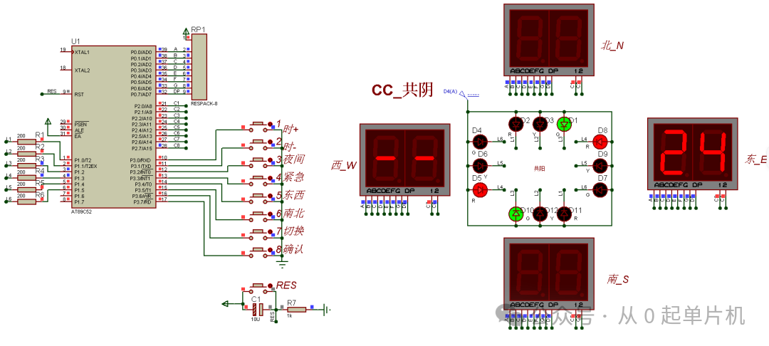
This project implements the control principle of traffic lights at an intersection based on the STC89C51/52 microcontroller. The time is displayed on a digital tube for all four directions, and there are 9 buttons, which are: reset button, night mode, emergency mode, east-west passage, north-south passage, time setting mode, time increase, time decrease, and confirm adjustment.
1. Function Description
1. Reset Button:
Restores system initialization
2. Night Mode:
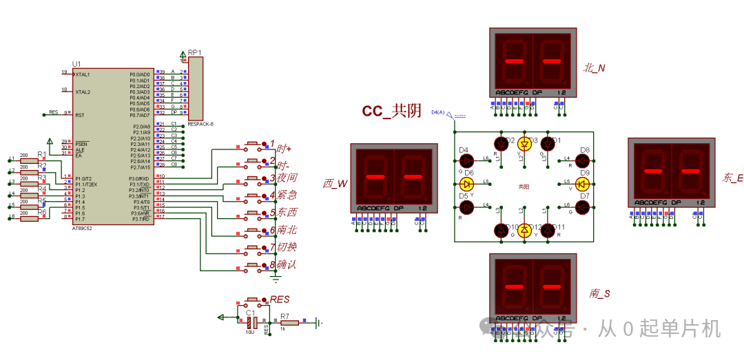
All digital tubes display “–“, yellow light flashes, other lights are off
3. Emergency Mode:
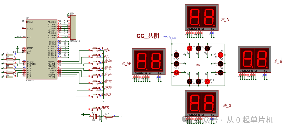
All digital tubes display “8.” all lights on, red light stays on
4. East-West Passage:
All digital tubes are off, green light stays on for east-west direction, red light stays on for north-south direction
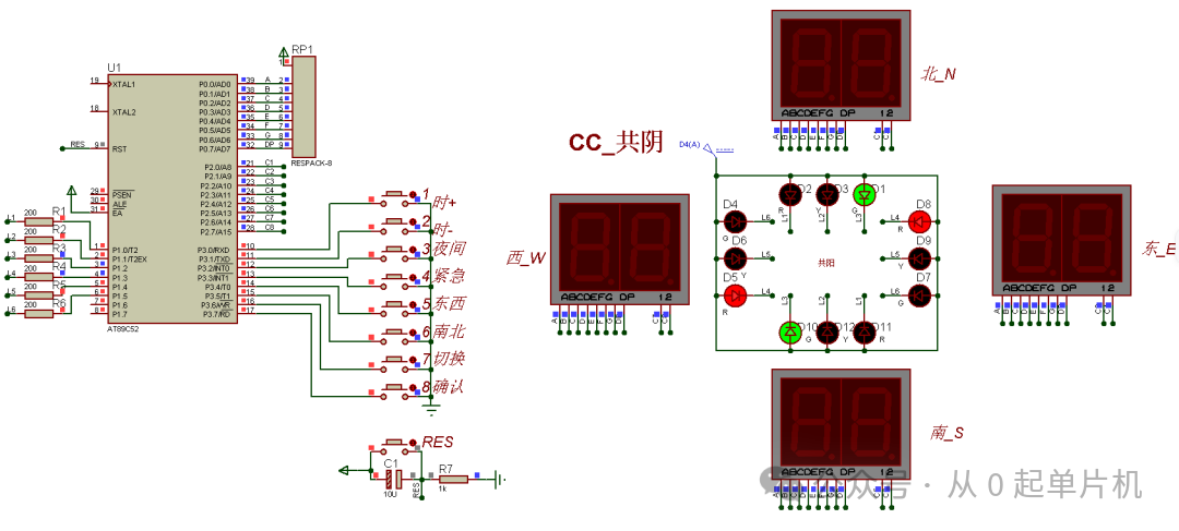
5. North-South Passage:
All digital tubes are off, green light stays on for north-south direction, red light stays on for east-west direction
6. Switch, Set Time:
1) In abnormal mode, press to return to normal working mode
2) In normal mode (automatic operation mode), press to switch to east-west direction time setting, north-south direction digital tubes are off, west shows “–“, east-west shows current time; press again to switch to north-south direction time setting, east-west direction digital tubes are off, north shows “–“, south shows current time; subsequent presses toggle the setting direction.
3) Time +/-: In time setting mode, increase or decrease time by 1
4) Confirm: Confirm settings are complete, return to normal working mode
2. System Schematic
1. Component List
1) AT89C51/52 microcontroller (ignore clock system in simulation) 1 piece
2) 10k resistor array 1 piece
3) Resistors several
4) Tactile switches 9 pieces
5) 10uF aluminum electrolytic capacitor 1 piece
6) Two-digit common cathode digital tube 4 pieces
7) Red, yellow, green LED lights 4 pieces each
2. Draw Schematic
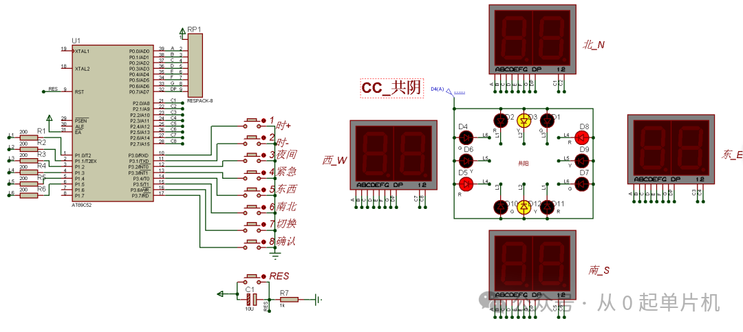
3. Program Writing
main.c Source Code
#include "STC89.H"
#include "Delay.h"
#include "Seg.h"
#include "Key.h"
#include "Led.h"
#include "Timer.h"

#define uint8_t unsigned char
#define uint16_t unsigned int

uint16_t count,count_Y; //1000 times counter
bit flag_Y; //1 yellow light flashing
bit flag_R; //1 red light all on
bit flag_SN_GO;
bit flag_EW_GO;

uint8_t SN_Go_Time=6; //North-South passage time
uint8_t EW_Go_Time=7; //East-West passage time

void Run_State(void);

void main(void)
{
  Timer0_Init();
  flag_SN_GO=1;
  flag_EW_GO=0;
  count = 0;    //initial counter
  while(1)
  {
 Run_State();
 Key_Return(); //Button scan
  }
}

void Run_State(void)
{
   while(Run==0) //Time setting mode
   {Set_SN_Tim();}
   if(Run==1)//Running mode
   {
  Night_Mode(); //Night mode
  SOS_Mode(); //SOS mode
  GO_Mode(); //GO mode
   }
   else if(Run==2) //East-West
   {
  P0=0x00;
  SN_G=1;EW_G=0;
  SN_R=0;EW_R=1;
   }
   else if(Run==3) //North-South
   {
  P0=0x00;
  SN_G=0;EW_G=1;
  SN_R=1;EW_R=0;
   }
}

/* Timer0 interrupt routine */
void tm0_isr() interrupt 1
{
    TL0 = T1MS;        //reload timer0 low byte
    TH0 = T1MS >> 8;   //reload timer0 high byte
 count++;
 count_Y++;
 if(count_Y==500)
 {LED_Y();count_Y=0;}//Night mode
    if (count == 1000)               //1ms * 1000 -> 1s
    {
  if(GO==0)
  {SN_Go_Time--;}
  if(GO==1)
  {EW_Go_Time--;}
  count = 0;
  if(SN_Go_Time==0)
  {
   GO=1;
   SN_Go_Time=Set_SN_time;
  }

  if(EW_Go_Time==0)
  {
   GO=0;
   EW_Go_Time=Set_EW_time;
  }
    }
}
… (remaining code omitted for brevity)
4. Simulation Results (Display Section)
1. Night Mode
2. Emergency Mode
3. North-South Passage
4. Setting Mode
5. Physical Schematic Drawing
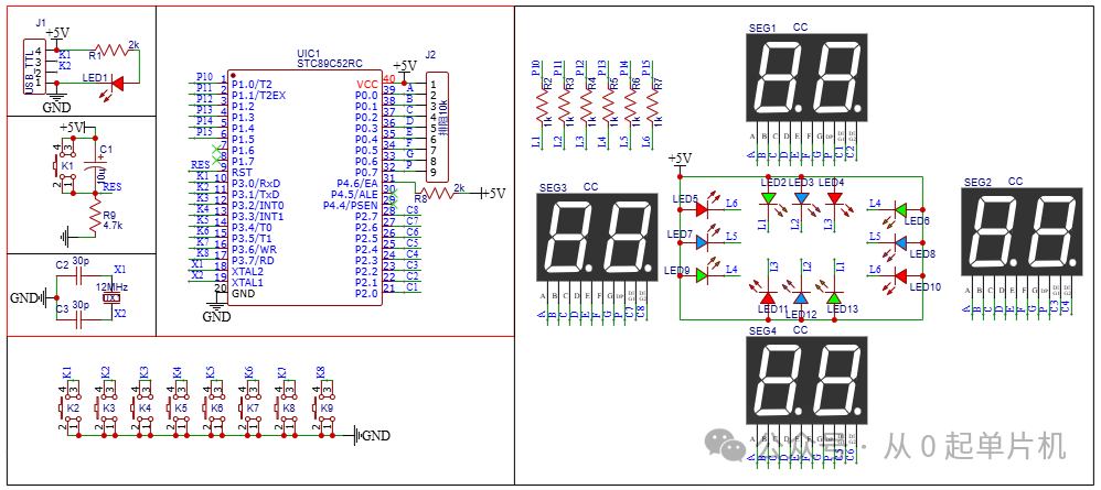
1. Schematic
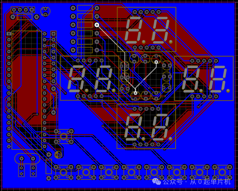
2. PCB
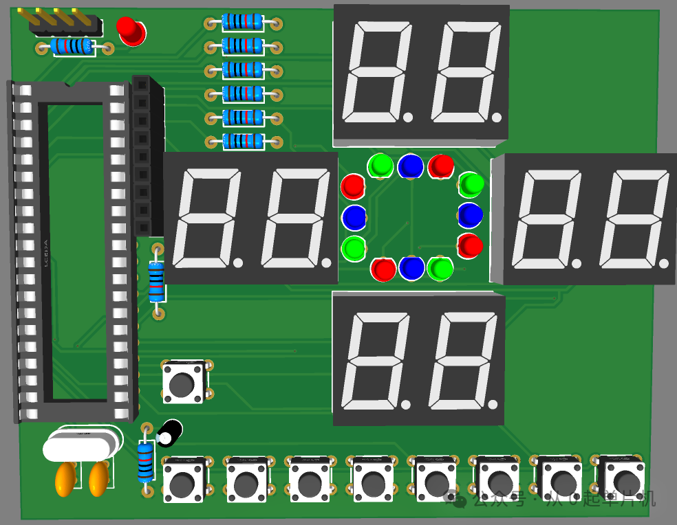
3. 3D Model
Conclusion:
The above content, except for the schematic which has not been verified with physical components, has been validated. If this is helpful to you, please do not hesitate to like, follow, and comment. Stay tuned for more practical cases.
Welcome to follow (this public account regularly shares microcontroller examples to help everyone grow from 0 to 1), click the blue text “Microcontroller from 0” at the top or long press to identify the QR code to follow
 Leave a message to obtain the source file and customize functions.