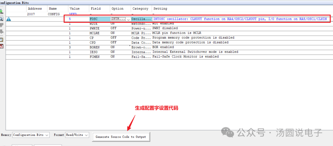
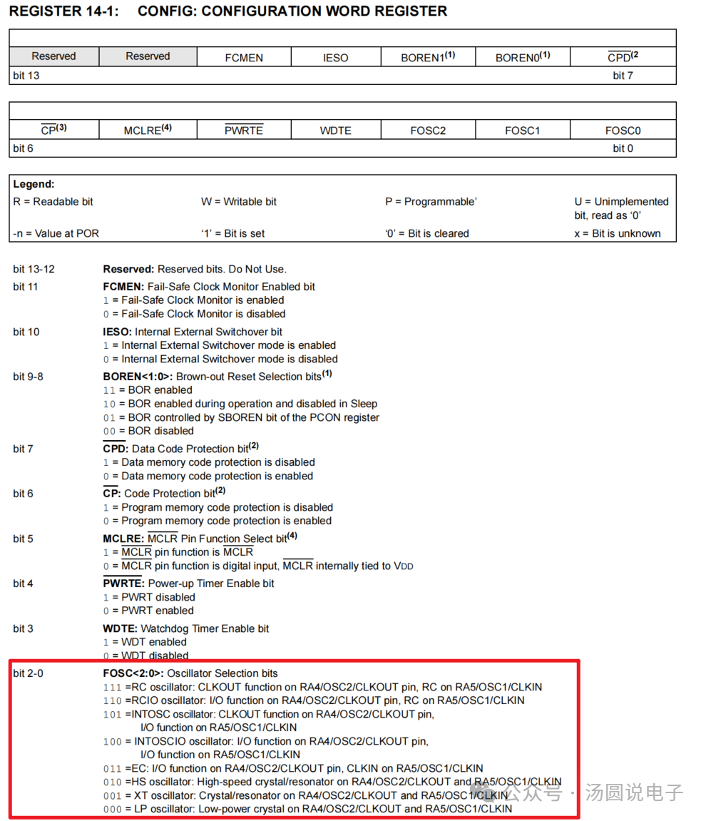
Get the demo source code file at the end of the article ↓Software Platform: MCC v5.5.2, MPLAB X IDE v6.25Hardware Platform:PIC16F685Basic settings for configuring the microcontroller startup – Configuration WordSet system clock source and other parameters through the microcontroller configuration word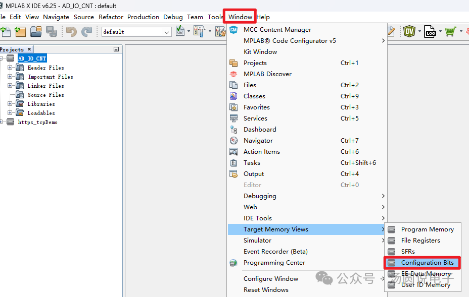 Set relevant configuration words in the configuration word interface and generate codeSet system clockFOSCto internal clock
 Copy the code before the main function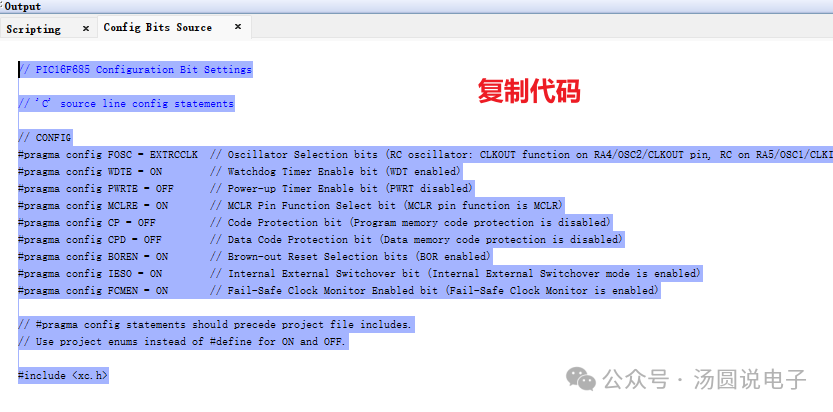
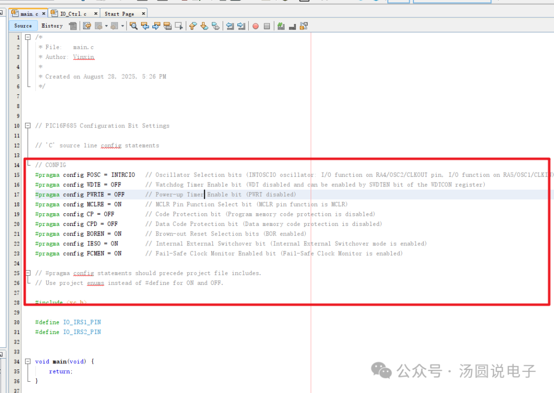 PIC16F685Microcontroller header file lookup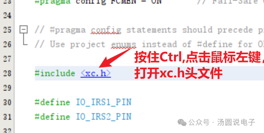
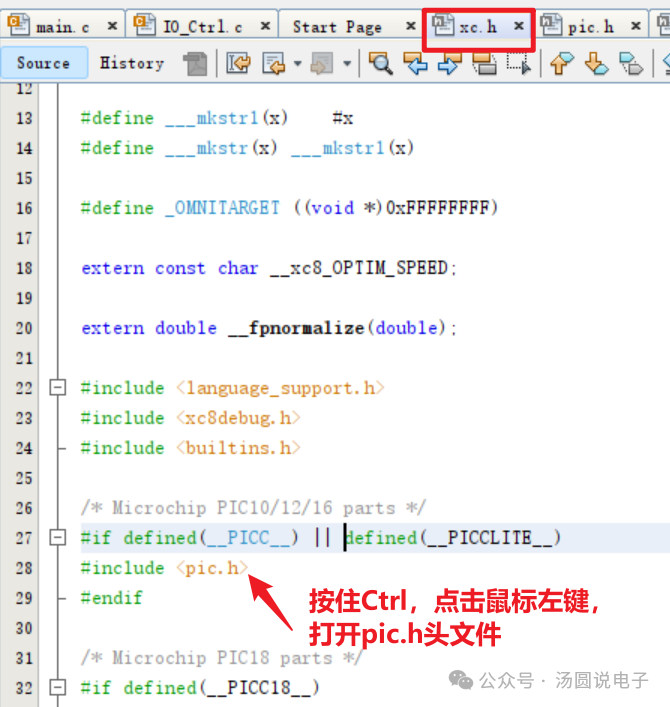
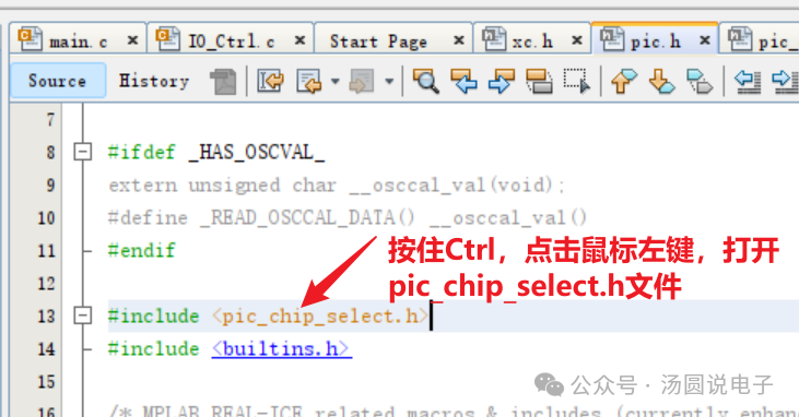
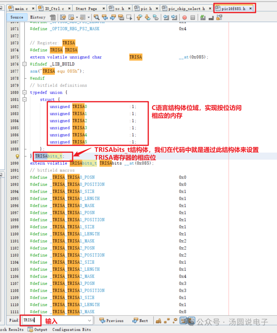
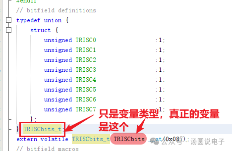
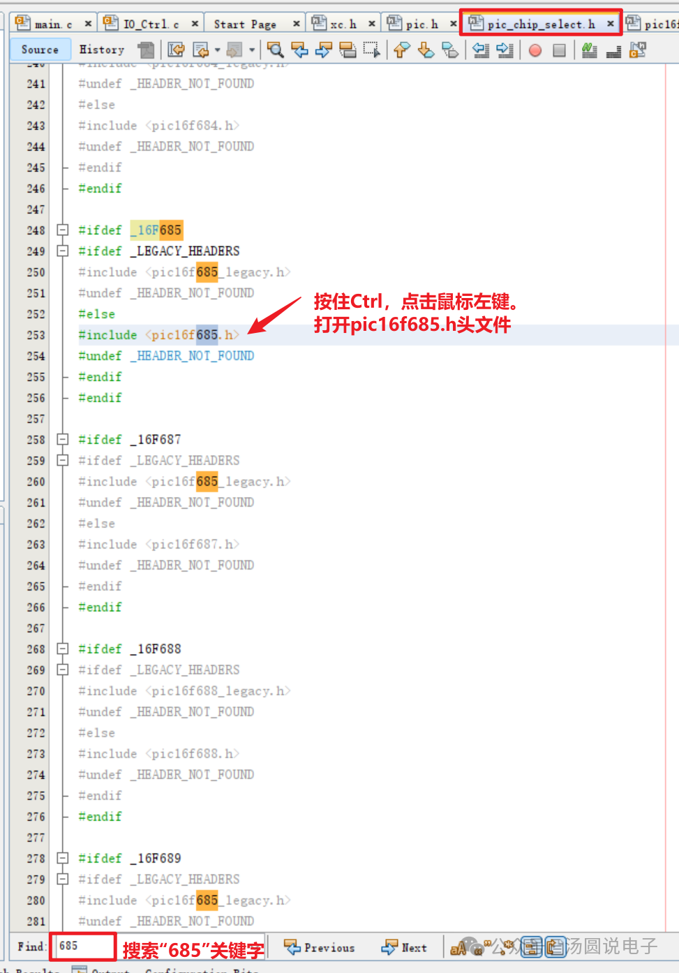 Check the names and definitions of peripheral register structure variables for easier programming later.
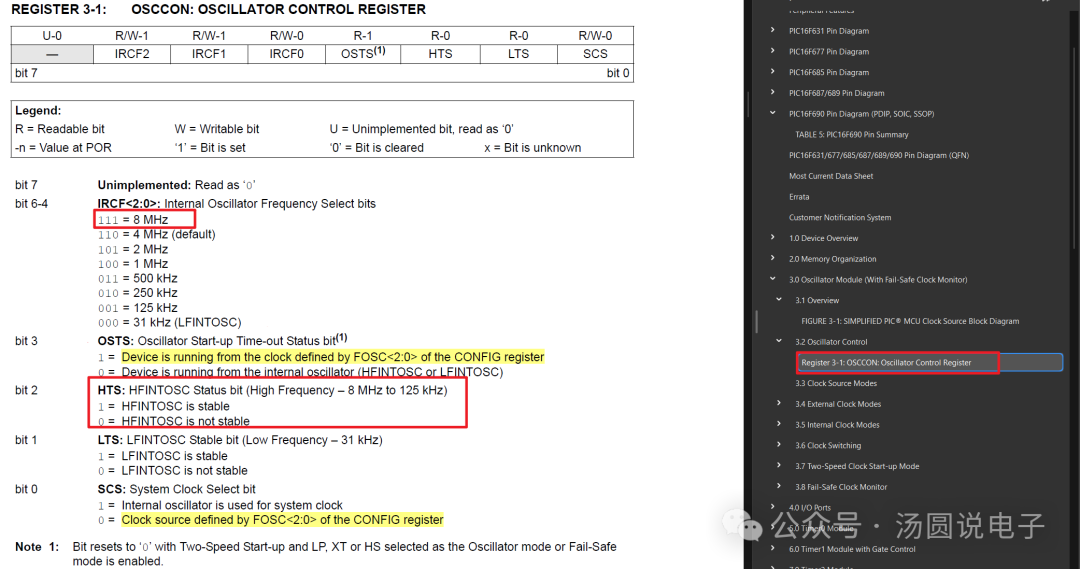
 Set the clock for the PIC16F685 microcontrollerRefer to Chapter 3 of the manual for the clock module, using an internal 8MHz clock frequency as the system internal clock.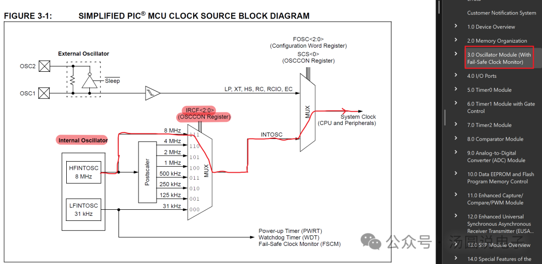
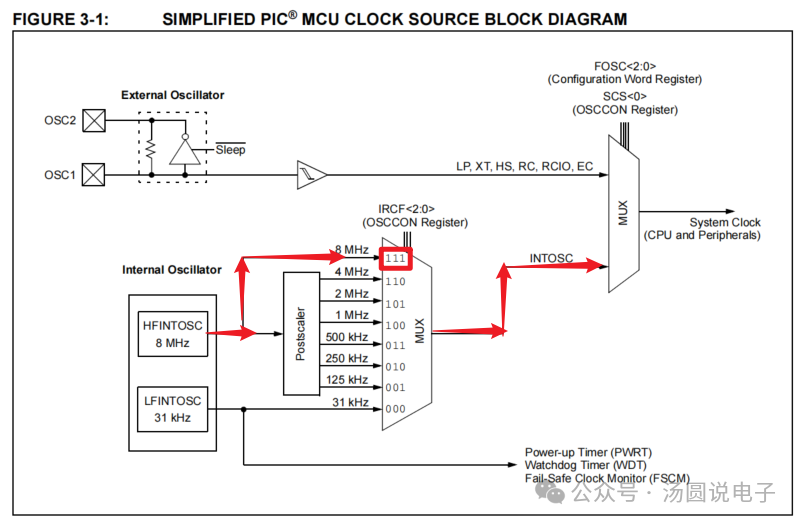 After setting the clock source in the configuration, the OSCCON register also needs to be configured
 Clock control register, select internal clock 8MHz
 Set the system clock to 8MHz
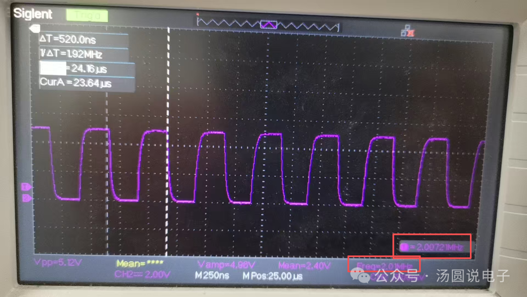
void System_ClockInit(void){ OSCCONbits.IRCF = 0x07; // select 8MHz fosc while(!OSCCONbits.HTS); // wait for HFINTOSC to stabilize}The configuration word sets the system clock output pin to RA4 (CLKOUT), from the manual, the clock frequency output from this pin is 1/4 of the system clock frequency.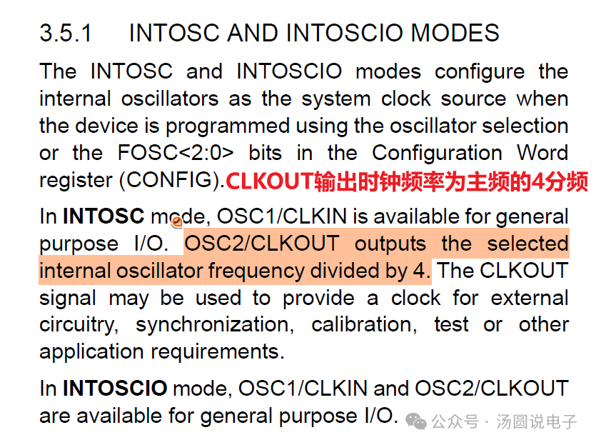 Here, the system main frequency clock is set to 8MHz, so the measured waveform frequency at the CLKOUT pin should be 2MHz, as shown below:
 Using IO PortsRefer to Chapter 4 of the manual for IOFrom the manual, we can see that clearing the corresponding bits of TRISA sets the corresponding IO ports to output functionality.
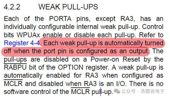
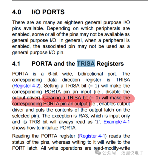 When the IO port is set to output functionality, the upper bits are automatically disabled
 Set IO to digital mode using registers ANSEL and ANSELH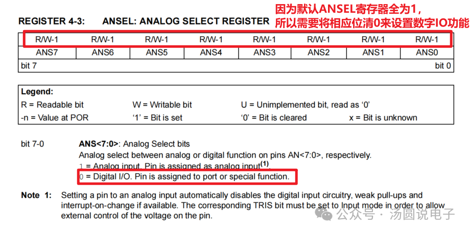
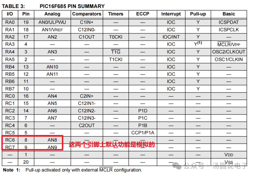 ANSELH register structure in the chip header file
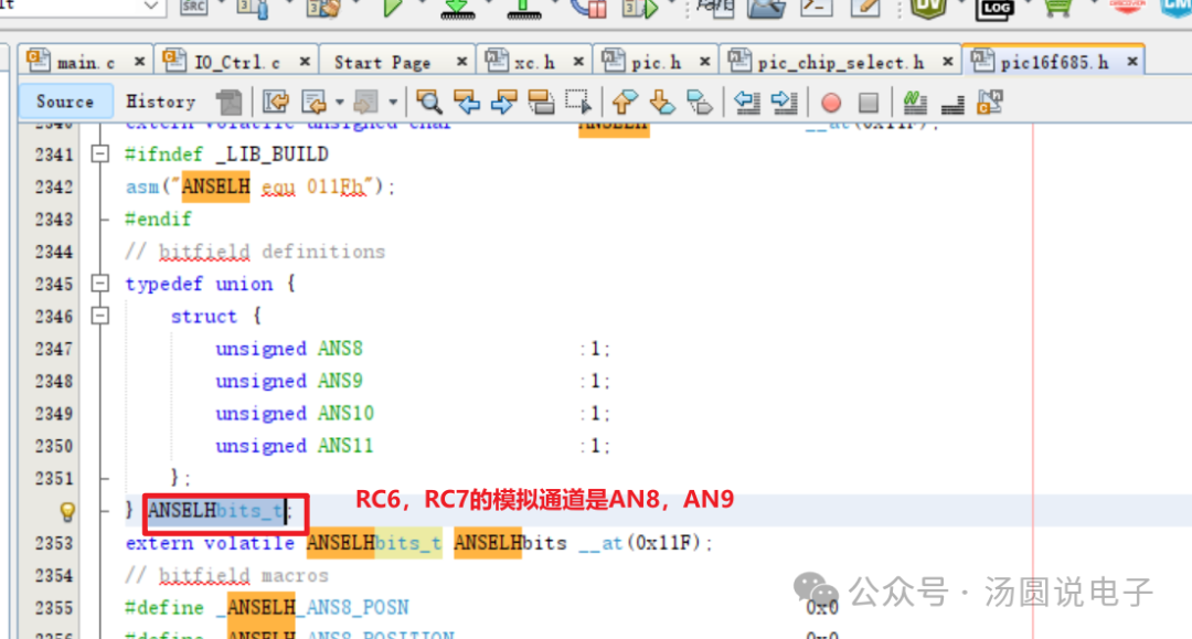 Set IO to output functionality
//===========IO port Init==============        // setting output for IO port    TRISCbits.TRISC6 = 0;    TRISCbits.TRISC7 = 0;    TRISBbits.TRISB7 = 0;    TRISBbits.TRISB4 = 0;
    // setting IO function to Digital    ANSELHbits.ANS8 = 0;    ANSELHbits.ANS9 = 0;    ANSELHbits.ANS10 = 0;
Set IO to input functionalityIndividual IO port pull-up settings are configured using the WPUx register, such as the pull-up register WPUA for the RA port. However, there is also a global pull-up enable bit: nRABPU in the OPTION register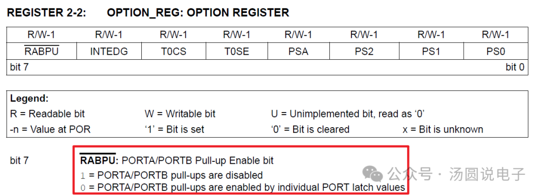 Global pull-up enable settingsSet IO pins to input mode
 void Init_ALL_IO_input(void) {        OPTION_REGbits.nRABPU = 0;// enable individual pull-up
    //===========IO port Init==============            // setting input for IO port        TRISBbits.TRISB5 = 1;        TRISBbits.TRISB6 = 1;
        //setting output for IO port        TRISBbits.TRISB7 = 0;        TRISAbits.TRISA5 = 0;
        // set default low        PORTBbits.RB7 = 0;        PORTAbits.RA5 = 0;
        // setting IO function to Digital        ANSELbits.ANS0 = 0;        ANSELbits.ANS1 = 0;        ANSELbits.ANS2 = 0;        ANSELbits.ANS3 = 0;        ANSELbits.ANS4 = 0;        ANSELbits.ANS5 = 0;        ANSELbits.ANS6 = 0;        ANSELbits.ANS7 = 0;        ANSELHbits.ANS8 = 0;        ANSELHbits.ANS9 = 0;        ANSELHbits.ANS10 = 0;        ANSELHbits.ANS11 = 0;
        //enable RB5\RB6 weak pull-up        WPUBbits.WPUB5 = 1;        WPUBbits.WPUB6 = 1;
 }
Pull-up resistor value calculationFrom Chapter 17 of the data manual, we obtain the pull-up current for the IO pins.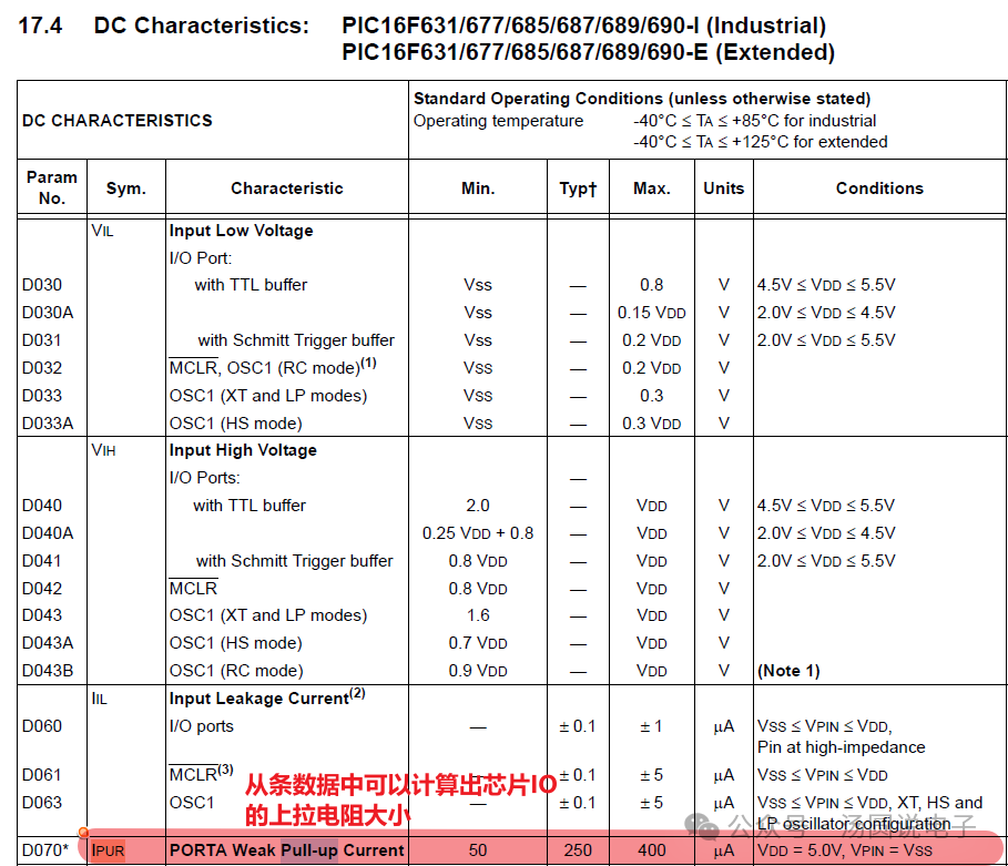 When the input voltage is 5V, the current is 400uA, the corresponding resistance is as follows:
 When the input voltage is 5V, the current is 50uA, the corresponding resistance is as follows:
 Using Timer 2Refer to Chapter 7 of the data manual for Timer 2
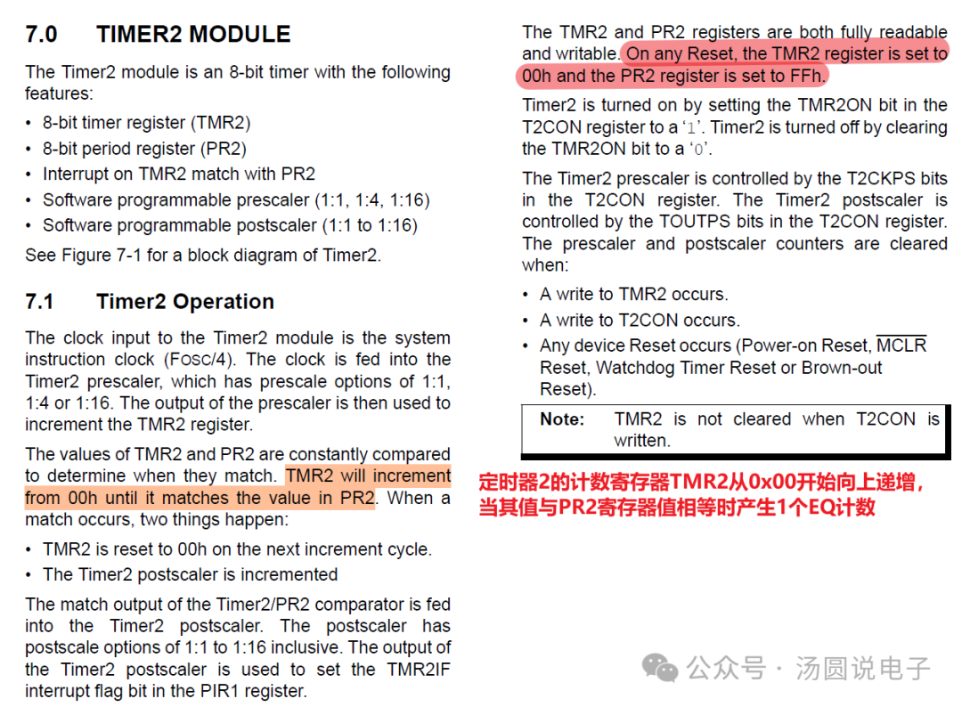 From the Timer 2 block diagram, it can be seen that Timer 2 needs to set registers T2CKPS<1:0>, PR2, TOUTPS<3:0>, etc.
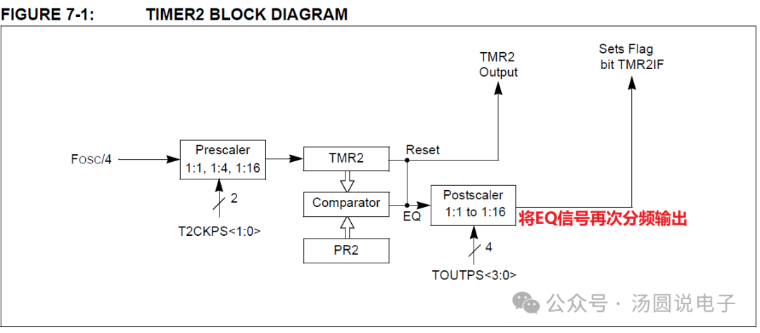 TMR2 starts counting from 0x00, and when it reaches the value set by PR2, the counter of Timer 2’s post-scaler increments by 1. This is equivalent to 8M/4/16/16,Timer initialization code
void Timer2_Init(void){    T2CONbits.T2CKPS = 0x02; // 1:16 Prescaler    T2CONbits.TOUTPS = 0x0F;
    PR2 = 0x4E;
    PIE1bits.TMR2IE = 1;
    T2CONbits.TMR2ON = 1; // start Timer2}
Using InterruptsRefer to Chapter 14 of the manual for interrupt content, where the interrupt function entry is 0x0004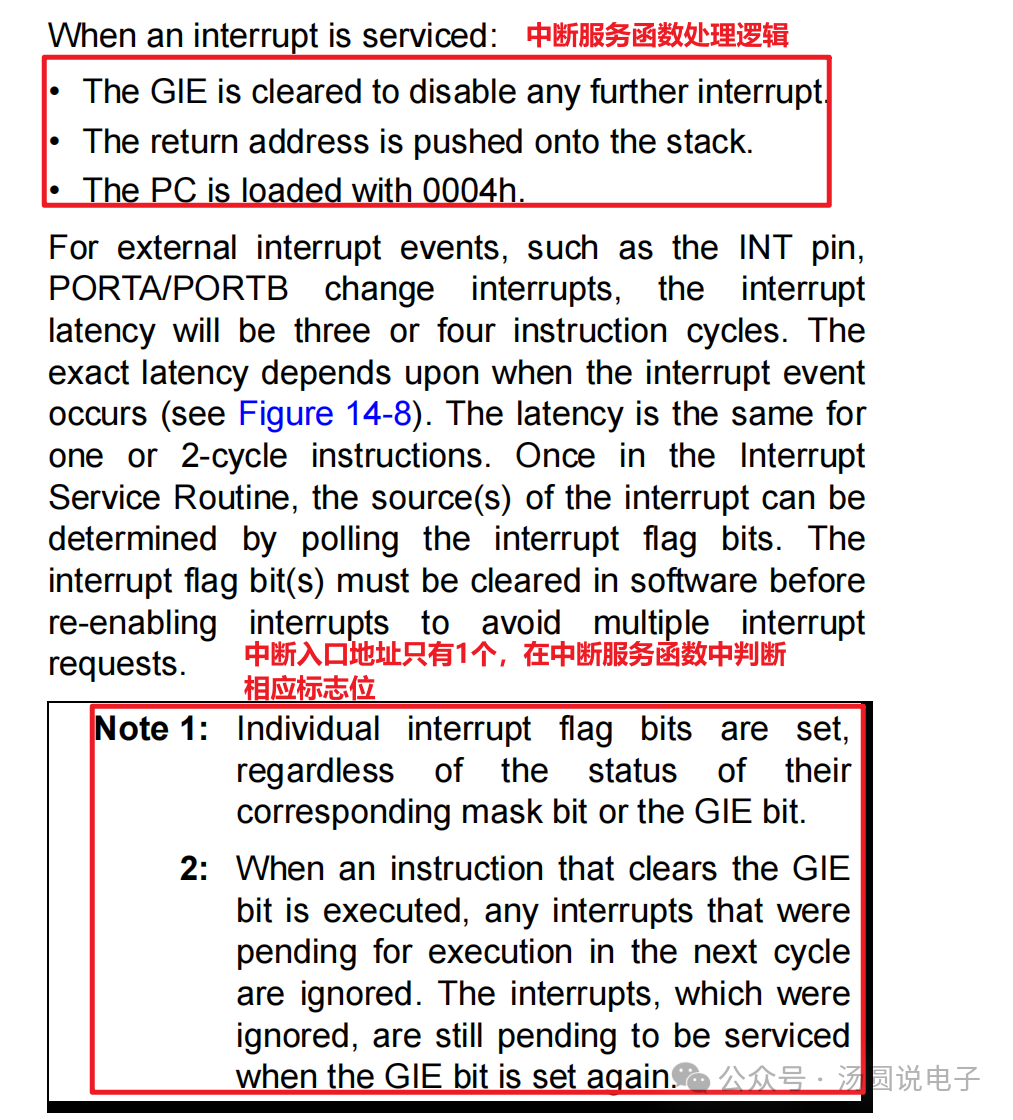 The interrupt block diagram is shown below. From the diagram, it can be seen that if a response to Timer 2 interrupt is needed, the Timer 2 interrupt enable bit TMR2IE needs to be set to 1, the peripheral enable bit PEIE needs to be set to 1, and the global interrupt enable bit GIE needs to be set to 1.
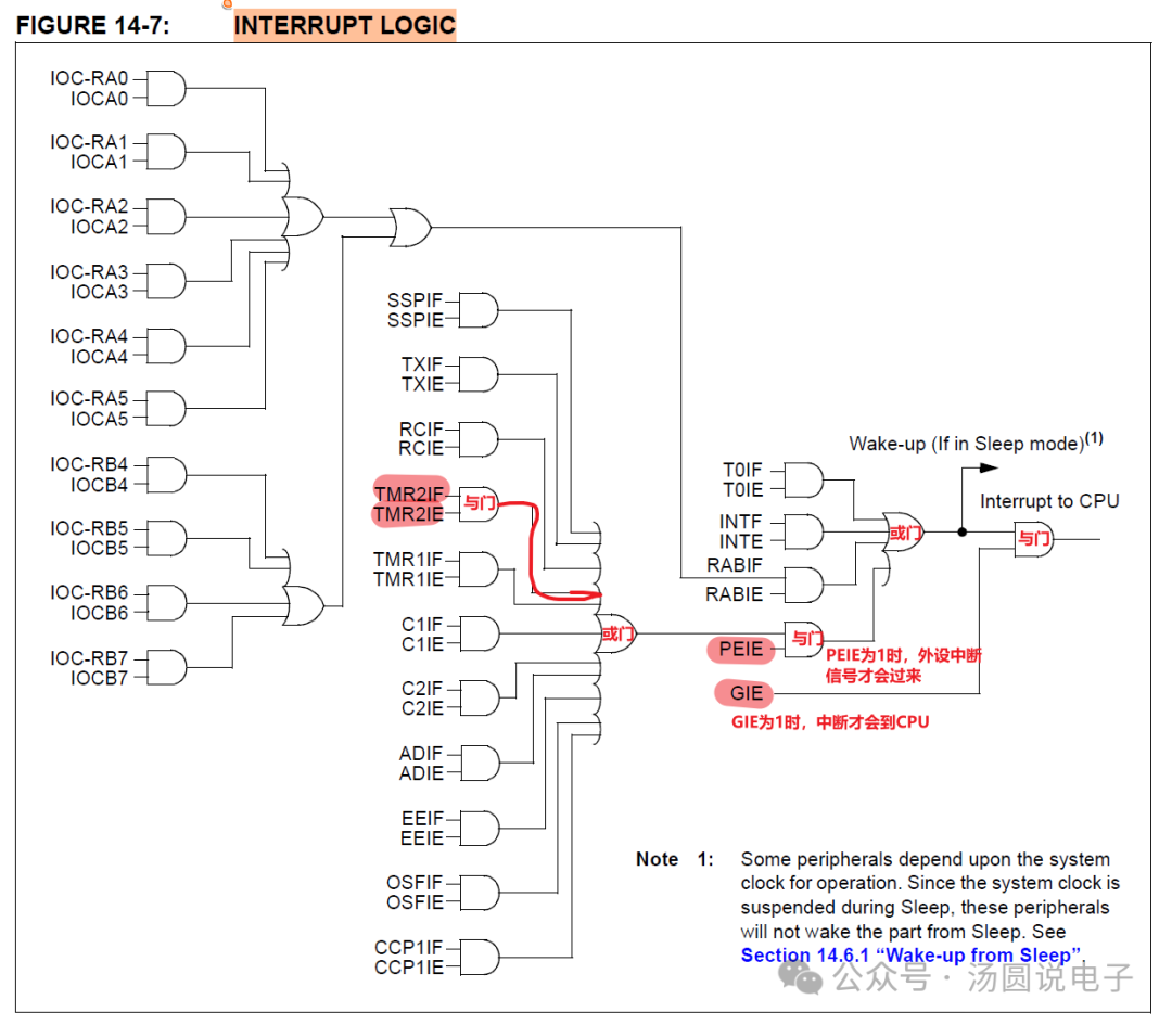 Interrupt enable code
// enable global interrupt INTCONbits.GIE = 1; // enable peripheral interrupt INTCONbits.PEIE = 1;Using and writing interrupt functionsOpen the compiler documentation in the installation directory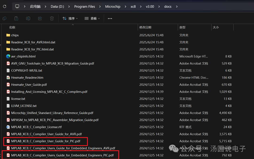 For microcontrollers with only one interrupt vector, the keyword for the interrupt service function is__interrupt()
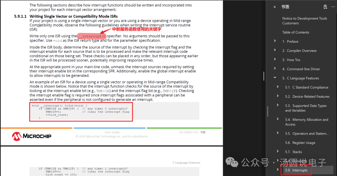 Interrupt service function
void __interrupt() All_Int(void) {    // disable global interrupt    INTCONbits.GIE = 0;
    // timer2 interrupt    if(PIR1bits.TMR2IF)    {                // clear Timer2 overflow interrupt        PIR1bits.TMR2IF = 0;        if(led_delay_ms++ >= LED_500MS)        {            led_delay_ms = 0;
#ifdef OUTPUT_IO_TEST            PORTBbits.RB5 = ~PORTBbits.RB5;            PORTBbits.RB6 = ~PORTBbits.RB6;
            PORTCbits.RC6 = ~PORTCbits.RC6;            PORTCbits.RC7 = ~PORTCbits.RC7;
            PORTBbits.RB7 = ~PORTBbits.RB7;            PORTBbits.RB4 = ~PORTBbits.RB4;
#endif
        }
    }    INTCONbits.GIE = 1;}
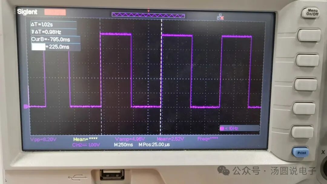
Downloader settingsThe default downloader keeps the MCU in reset state after downloading the program. At this point, it is necessary to modify the configuration as shown below. After the program is downloaded, it can run, as shown below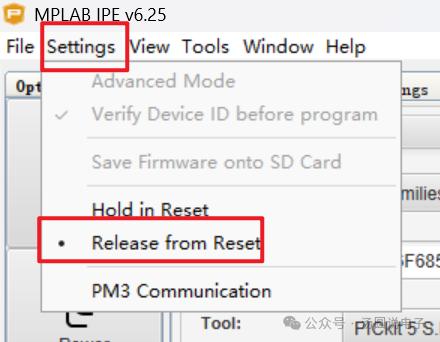 Using Timer 2 to generate a square wave with a 1-second period
 Other issues: Compilation reports “missing (” issue, its real-time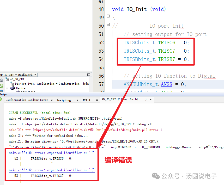
 Project code download link
Link: https://pan.baidu.com/s/1jWi5vh36lr_uIlgdgBfQ_Q
Follow “Tangyuan Talks Electronics” and reply with the keyword: 16F685_IO,to get the extraction code