1. Overview of MODBUS Communication
The MODBUS protocol is divided into MODBUS protocol over serial links and MODBUS protocol based on TCP/IP. The serial link MODBUS protocol includes MODBUS ASCII (string) and MODBUS RTU.
The MODBUS protocol library provided by 200SMART supports MODBUS RTU communication.
MODBUS RTU sends data in hexadecimal values.
MODBUS ASCII sends data in ASCII code; sending one data using RTU requires only one byte, while sending with ASCII code requires two bytes, resulting in longer transmission time.
There are many communication methods for PLC and frequency inverter serial communication, but the commonly used and preferred method is MODBUS communication, which is widely applied in actual industrial control. In this issue, we will share how to control the frequency inverter with PLC using MODBUS RTU.
2. Detailed Explanation of MODBUS Library Instructions
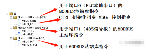
Library instructions are divided into two types: master library and slave library.
The master is PLC acting as the MODBUS master to actively read data from other devices; the slave is PLC acting as the MODBUS slave, with other devices reading data. This issue shares PLC as the master and frequency inverter as the slave.
STEP7-MinWIN SMART software comes with MODBUS communication library instructions.
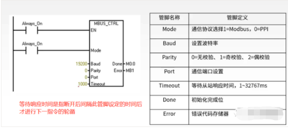
Initialization Instruction:
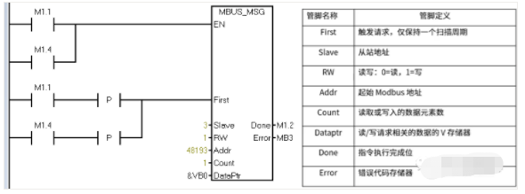
Control Instruction:
3. Communication Format (Protocol) of MODBUS RTU
The communication protocol consists of: station number, function code, data address, data content, checksum, and end character.
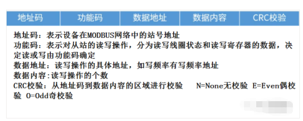
Checksum: N=None no checksum E=Even even parity O=Odd odd parity.
Determine whether the number of bits that are 1 is odd or even (for even parity, if the number of 1s is even, the checksum is 1; if odd, the checksum is 0. For odd parity, if the number of 1s is even, the checksum is 0; if odd, the checksum is 1).
The function code specifies whether to read or write operations on the slave device and also specifies the type of MODBUS register address. Common function codes include:
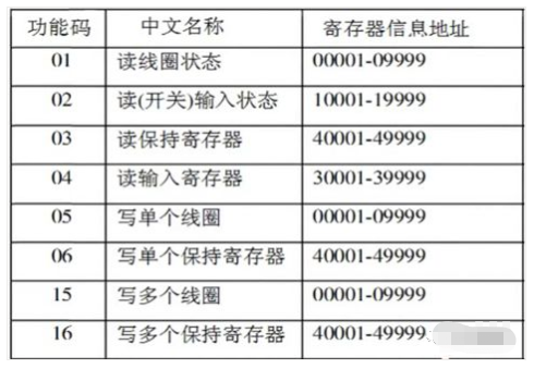
4. Hardware Connection for Communication Between PLC and Frequency Inverter
On the frequency inverter, communication terminal markings include A/B RS585+/RS485- or RJ11 port; find the relevant frequency inverter manual to check the wiring definitions of the communication ports. Below is the wiring definition for the Delta VFD-M series frequency inverter communication port.
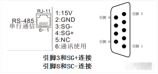
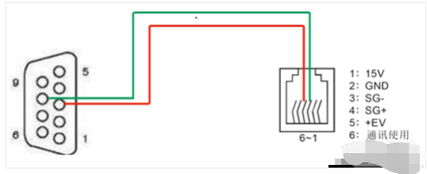
5. Setting Communication Parameters for Frequency Inverter
1. To achieve normal communication between the frequency inverter or instrument and PLC, their interfaces and protocols need to be consistent, and in addition, the parameter settings must also be consistent.
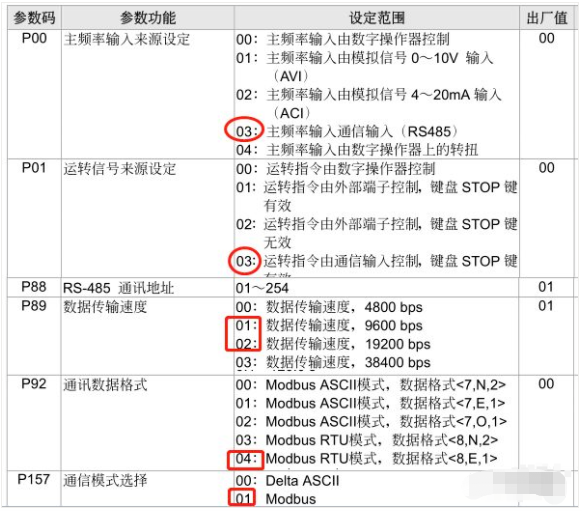
P00 set 03 (frequency command) P01 set 03 (run command) P88 set 03 (communication address, between 0-254) P89 set 02 (baud rate selection) P92 set 04 (data format, 200SMART does not support 2 stop bits, so you can only choose 04/05 as any parameter) P157 set 01 (the default mode of the frequency inverter is MODBUS mode).
2. Check the address of feedback parameters such as start/stop, frequency setting, running frequency, voltage, and current in the manual.
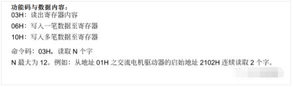
Description of information frame format.
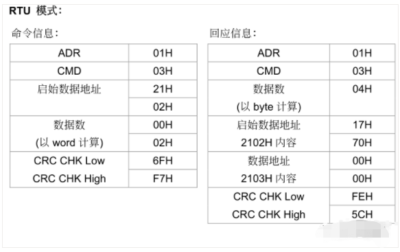
Indicates that the data read from addresses 2103 and 2104 is placed in addresses 17 70 and 00 00, the parameter address definitions of the communication protocol:
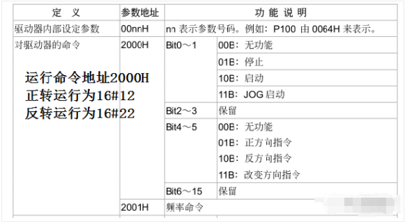
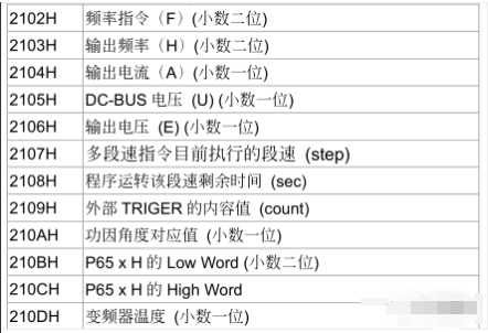
Run command address 2000H frequency command address 2001H output frequency address 2103H output current address 22104H output voltage address 2106H frequency inverter temperature address 210DH.
6. Writing the MODBUS Communication Program
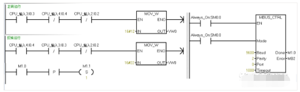
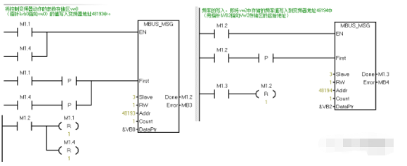
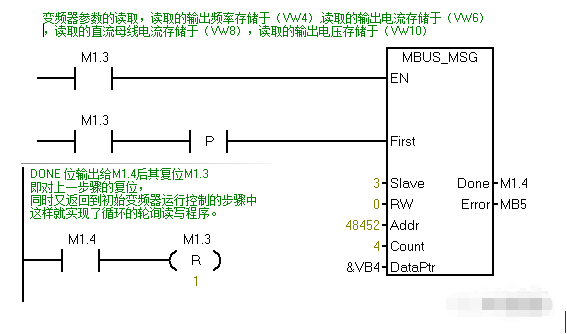
At the start of the program, you can add a segment to initialize and reset all bits.
-
(Content sourced from the internet, copyright belongs to the original author.)
-
Disclaimer: If there are copyright issues, please contact for deletion! No individual or institution shall bear relevant legal responsibility.
-