Profibus-DP Communication Between S7-200 and S7-300
PROFIBUS Fieldbus
1. Profibus-DP Communication Between S7-200 and S7-300 PLCs
1. Analysis: The S7-200 PLC does not support the DP communication protocol and does not have a Profibus-DP interface, so it cannot be directly connected as a slave. However, it can be connected to the Profibus-DP network by adding an EM277 module, manually setting the DP address, and making the S7-200 act as a slave.
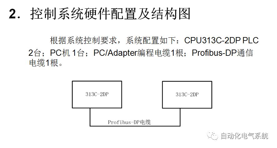
2. Hardware Configuration
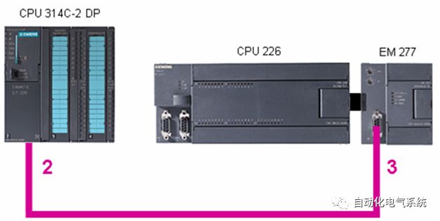
Figure 1: System External Wiring Diagram
The EM277 Profibus-DP module is an intelligent module with an isolated RS-485 interface. The port baud rate ranges from 9.6Kbit/s to 12Mbit/s, adapting to the communication speed of the system. As a DP slave, the EM277 accepts I/O configuration from the master and sends and receives data to and from the master; the master can also read and write to the S7-200 PLC’s V memory area, exchanging 1 to 128 bytes with EM277 each time.
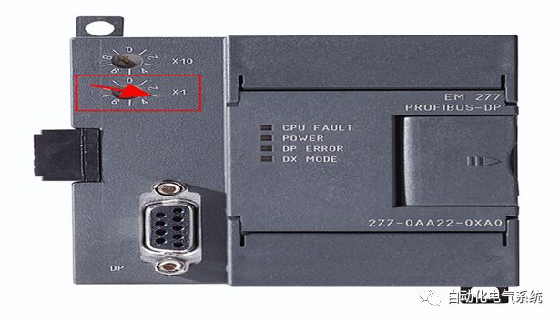
3. Slave Settings
Turn off the power supply to the module.
Set the predefined Profibus-DP address on the EM277.
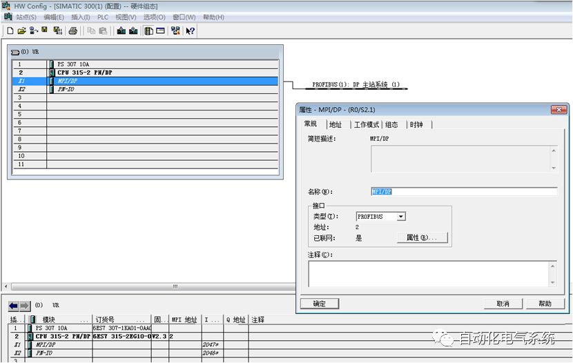
4. Master Station Hardware Configuration
1) Enter the SIMATIC Manager interface, click on File, and select New.
Create a new project.

2) Open the “HW Config” editor, find and insert the rack and CPU315-2PN/DP PLC in the hardware directory on the right side of the interface.
3) Install the GSD file. Go to “Options” and install the GSD file.
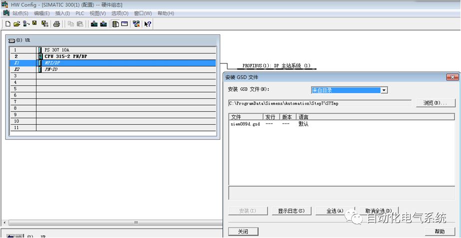
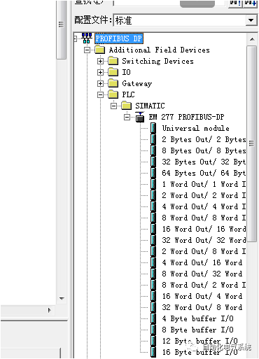
4) After successfully installing the GSD file, you can find the EM277 module information in the right directory of the “HW Config” interface.
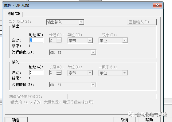
5) Set the sending and receiving addresses for the master and slave.

6) Set the sending and receiving addresses for the master and slave.
4. Master Station Hardware Configuration
5. Notes
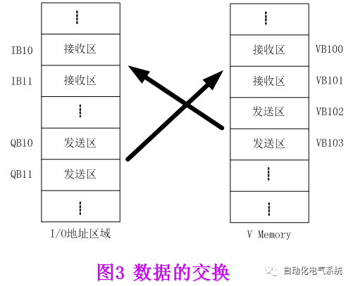
1) During operation, you can monitor the exchanged data in communication using the variable table of STEP7 and the status table of STEP7-Micro/Win;
2) In data communication, the data sent by the master is stored in the receiving area (variable storage area) of the slave. The user program of the S7-200 PLC must “transfer” this data to other data areas; otherwise, this data will be overwritten during the next data transmission.
3) Attention should be paid to data consistency issues in hardware configuration.
2. ProfiBus Communication Methods of S7-300 PLC
1. Use I/O ports to achieve direct ProfiBus communication for less than 4 bytes
2. Application of system functions SFC14 and SFC15 for ProfiBus communication
3. Achieve ProfiBus communication through CP342-5
1. Use I/O ports to achieve direct ProfiBus communication for less than 4 bytes
The method of directly using I/O ports to achieve direct ProfiBus communication for less than 4 bytes includes two aspects: (1) Using load instructions to access actual I/O ports — for example, communication between the master station and ET200M extended I/O ports; (2) Using load instructions to access virtual I/O ports — for example, communication between the master station and the I/O ports of intelligent slaves.
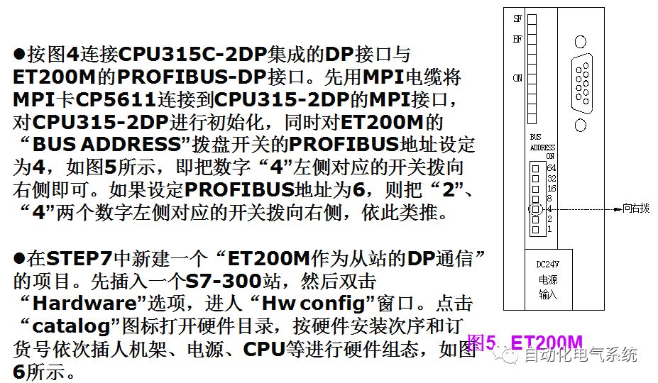
1) Remote communication between the CPU integrated DP port and ET200M
2) Connecting intelligent slaves through the CPU integrated DP port
1) Remote communication between the CPU integrated DP port and ET200M
The ET200 series is a remote I/O station. To reduce the laying of signal cables, different types of I/O stations, such as ET200M, ET200B, ET200X, ET200S, can be placed near the equipment according to different requirements. ET200M is suitable for use when there are many I/O points at remote stations. Below is an introduction to the configuration of remote I/O using ET200M, with the master station being the CPU with an integrated DP interface.
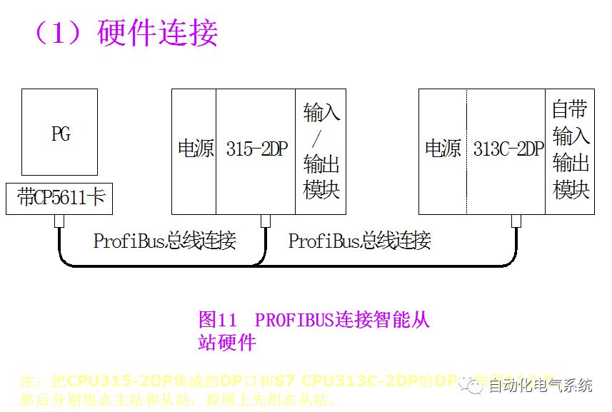
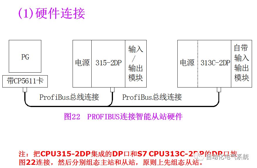
(1) Hardware Connection
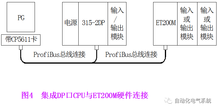
(2) Resource Requirements
The S7-300 CPU315-2DP with integrated DP port serves as the master station.
The slave station is ET200M with I/O modules.
MPI network card CP5611.
ProfiBus bus connector and cables.
STEP7 V5.2 system design software.
(3) Network Configuration and Parameter Settings
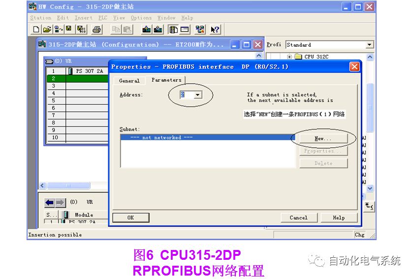
Insert the CPU, and the PROFIBUS configuration interface will pop up. Click the New button to create PROFIBUS (1), and configure the PROFIBUS station address to 2. Click the “Properties” button to configure network properties, select “Network Settings”, as shown in Figure 7, click the “OK” button to confirm, completing the creation of the PROFIBUS network, which will appear on the interface.

In the Profibus-DP options, follow the path “Profibus-DP” → “ET200M” → “IM153-1” on the left to select the interface module IM153-1 and add it to the PROFIBUS network, as shown in Figure 8. Adding is completed by dragging; if the position is valid, a “+” mark will appear on the mouse pointer, at which point release the “IM 153-1”. Upon releasing the mouse, a dialog box will pop up to configure the Profibus network parameters for IM153, as shown in Figure 9. The process of loading IM 153-1 onto the Profibus (1) network is illustrated, defining the Profibus station address for the ET200M interface module IM153-2, the configured station address must match the address set by the dial switch on IM153-2; in this case, the station address is 4. Then configure the I/O modules on ET200M, setting the address of the I/O points. The I/O address area of ET200M must not conflict with the central expanded I/O address area; in this case, 16 input and 16 output points are configured on ET200M, starting at address 1. When accessing these points, use the I area and Q area; for example, the input point is I1.0, and the first output point is Q1.0. In actual use, the I/O modules on ET200M behave as if they are integrated into the CPU 315-2DP, making programming very simple. The hardware configuration results are shown in Figure 10.


2) Connecting intelligent slaves through the CPU integrated DP port
Establish a communication system with 315-2DP as the master station and 313C-2DP as the intelligent slave, comprehensively introducing the configuration and usage of intelligent slaves.
(2) Resource Requirements
The S7-300 CPU315-2DP with integrated DP port serves as the master station.
The slave station is ET200M with I/O modules.
MPI network card CP5611.
ProfiBus bus connector and cables.¡¡STEP7 V5.2 system design software.
(3) Network Configuration and Parameter Settings
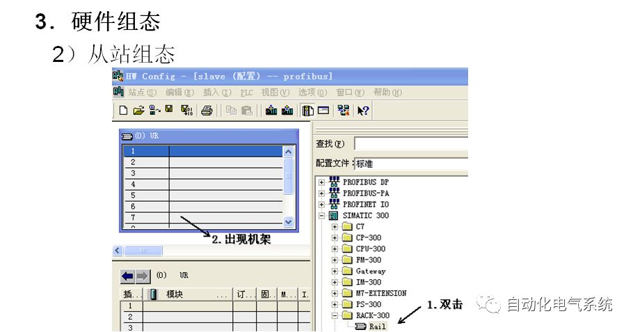
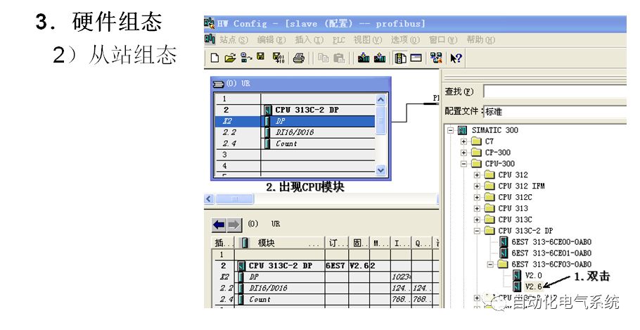
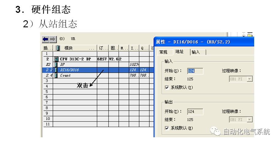
Configure the hardware of the “slave” station
Create a project for “communication between the master station and the intelligent slave” in STEP7. First, insert an S7-300 station, then double-click the “Hardware” option to enter the “Hw config” window. Click the “Catalog” icon to open the hardware directory, inserting the rack, power supply, CPU, etc., in order according to the hardware installation sequence and order number.
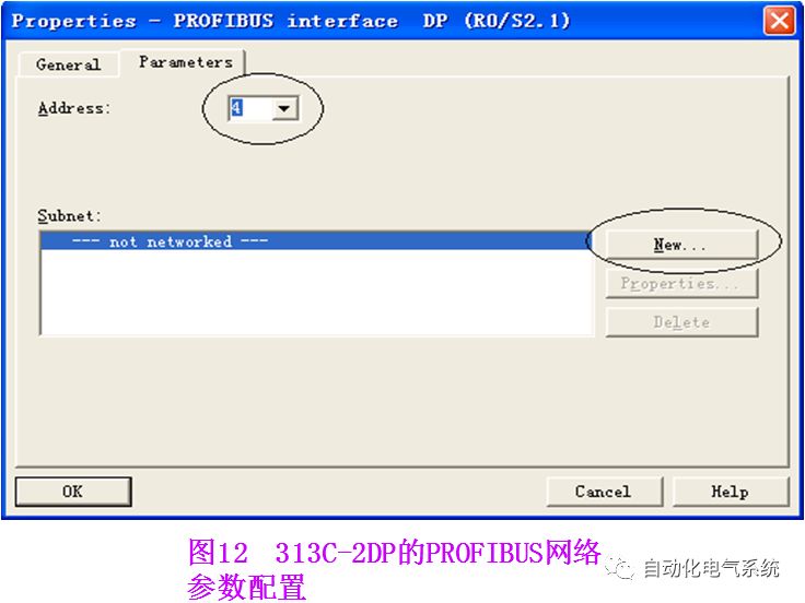
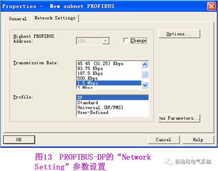
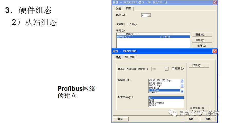
When inserting the CPU, the PROFIBUS configuration interface will pop up, as shown in Figure 12. Click the “New” button to create PROFIBUS (1), and configure the PROFIBUS station address, which is 4 in this example. Click the “Properties” button to configure network properties, selecting “Network Settings” for network parameter settings. In this example, the transmission rate of PROFIBUS is set to “1.5Mbit/s”, and the protocol is “DP”, as shown in Figure 13.
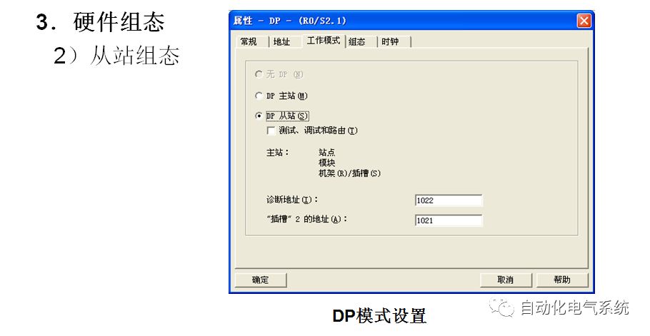
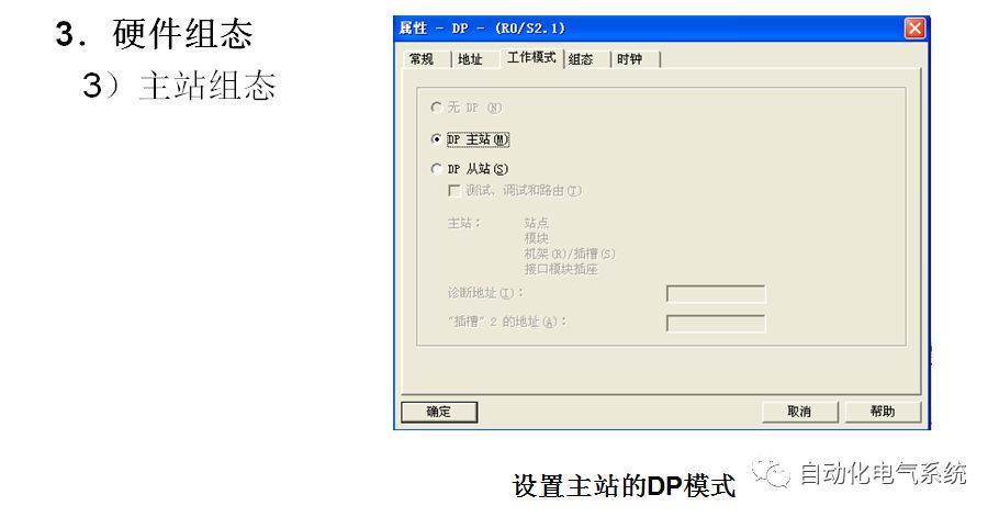
In the network properties window, select the top menu “Operating Mode”, and select “DP slave” operation mode. If the selection box below is activated, the programmer can program the slave; in other words, this interface can act as a DP slave while also monitoring the program through this interface. The diagnostic address is 1022, and the default value can be selected.
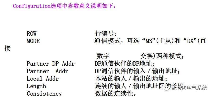
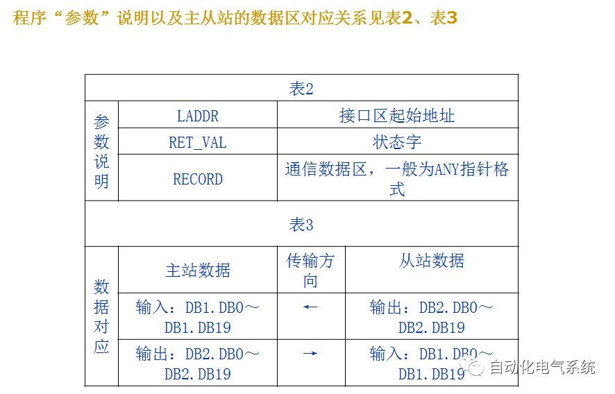
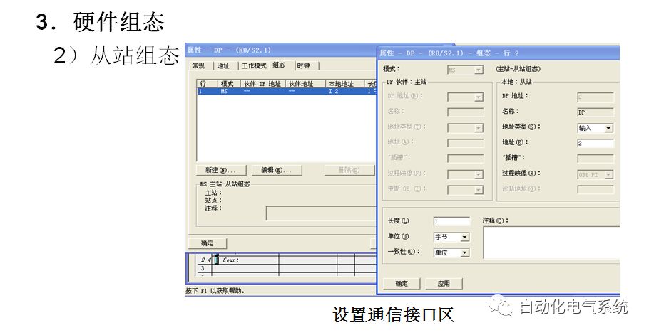
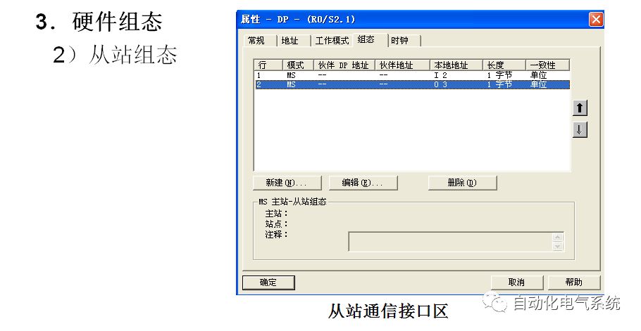
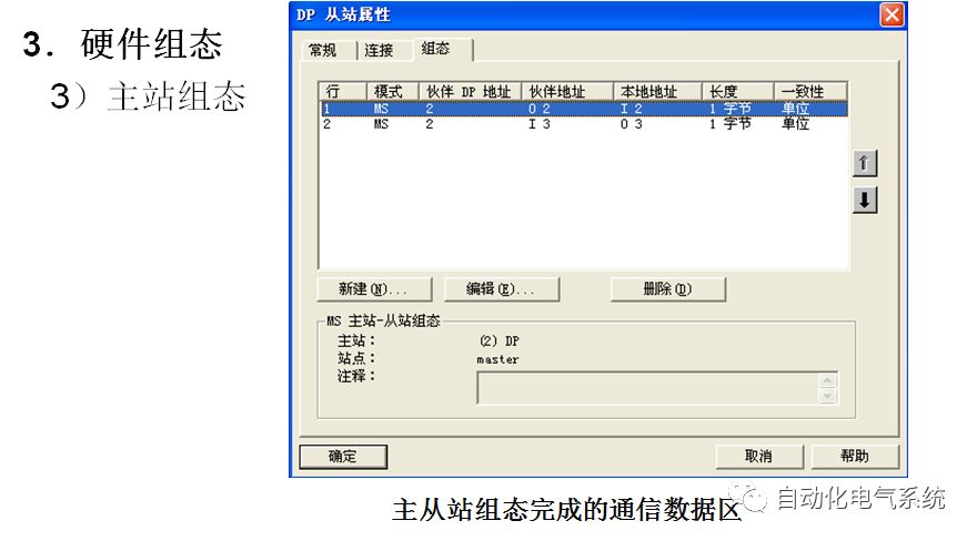
② Select the “Configuration” tab, click the “New” button to create a row of communication interface areas, as shown in Figure 15.
③ In Figure 15, define the communication interface area of the S7-300 slave.
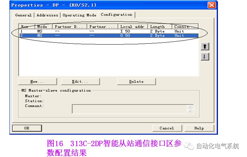
|
Table 1 |
|
|
Address type |
Select “Input” corresponding to the I area, “Output” corresponding to the Q area |
|
Length |
Set the size of the communication area, up to 32 bytes |
|
Unit |
Select whether to communicate by byte or by word |
|
Consistency |
Select “Unit” to send according to the data format defined in “Unit”, that is, by byte or by word; if “All” is selected, it means sending in packets with a maximum of 32 bytes per packet |
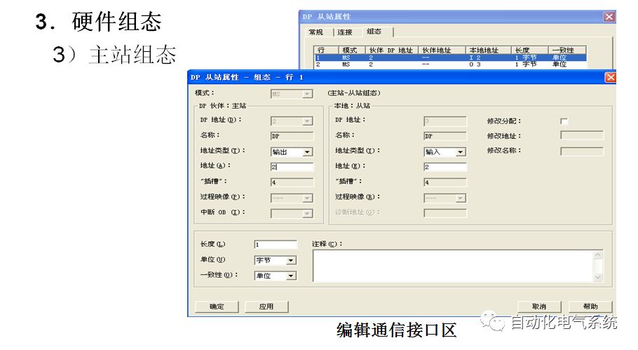
After completing the settings, click the “Apply” button to confirm. You can add several rows of communication data; the size of the communication area depends on the CPU model, with a maximum of 244 bytes. In Figure 16, the communication interface areas of the master station are virtual and cannot be operated on; when configuring the master station, the virtual options will be activated, allowing you to set the communication parameters of the master station.
In this example, an Input area and an Output area are set, both with a length of 2 bytes. After completing the settings, the two communication interface areas can be seen in the “Configuration” tab in Figure 16.
(4) Configure the hardware of the “master” station
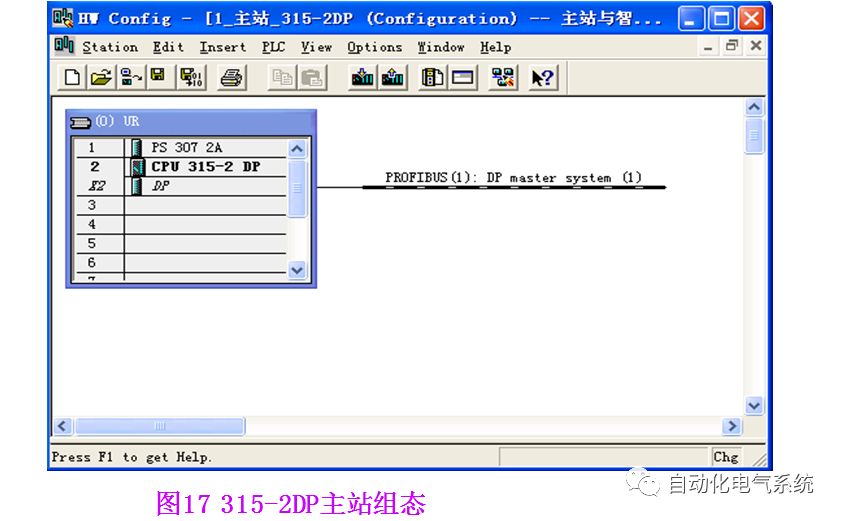
After configuring the slave, establish the S7-300 master station in the same way, setting the station address to 2 and selecting the same PROFIBUS network as the slave, as shown in Figure 17.
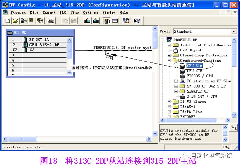
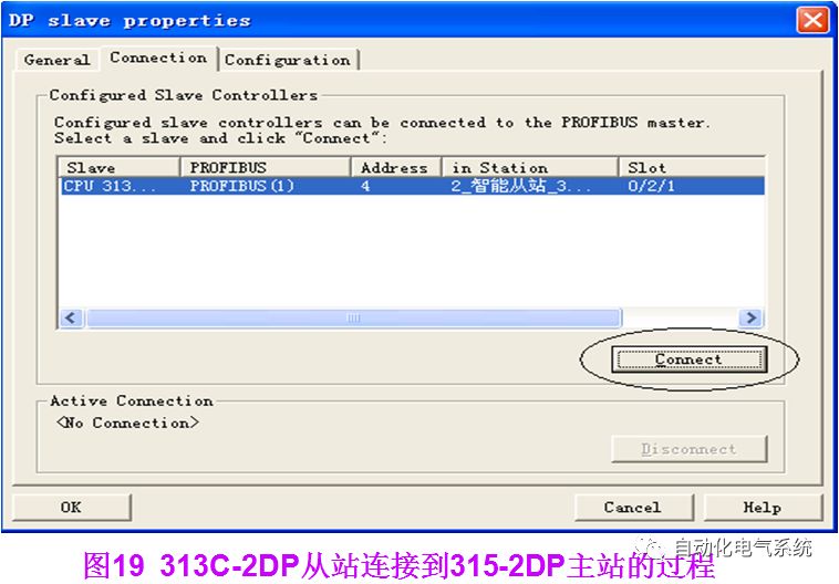
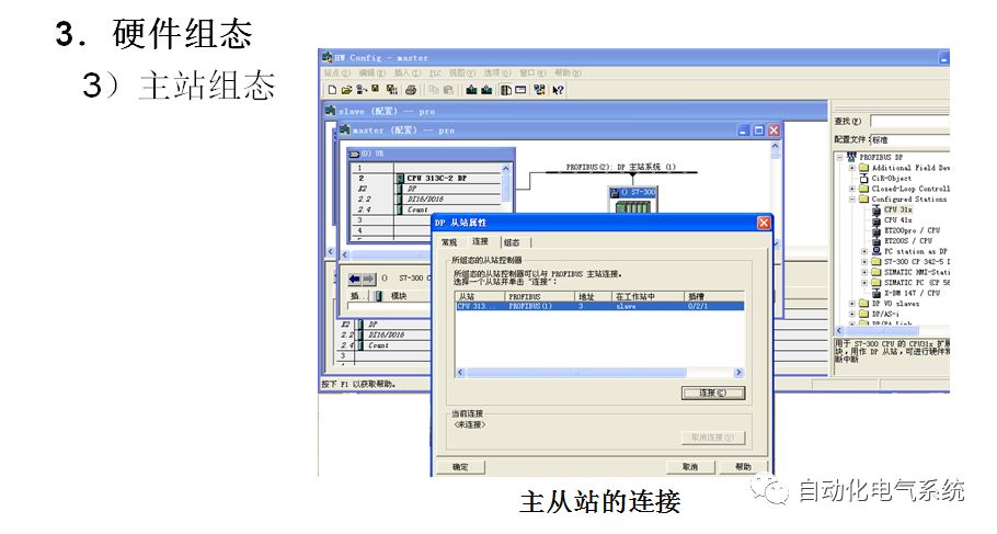
Open the hardware directory, select the “PROFIBUS DP→Configuration Station” folder, select CPU31x, and drag it onto the DP master station system’s PROFIBUS bus to connect it to the DP network, as shown in Figure 18. At this point, the “DP-slave Properties” will automatically pop up, and in the “Connection” tab, select the slave that has been configured. If there are multiple slaves, connect them one by one; the previously configured S7313C-2DP slave can be seen in the list. Click the “Connect” button to connect it to the network, as shown in Figure 19.
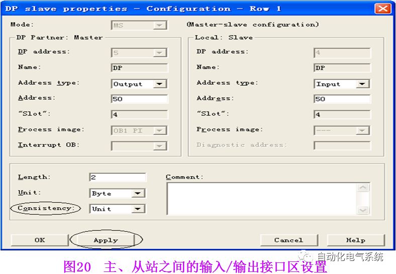
Then click the “Configuration” tab to set the communication interface area of the master station. The output area of the slave corresponds to the input area of the master station, and the input area of the slave corresponds to the output area of the master station, as shown in Figure 20, with the results shown in Figure 21.
After configuration, use the MPI interface to download the initialization interface data to each CPU. In this example, the data of QB50 and QB51 of the master station will automatically correspond to the data area IB50 and IB51 of the slave, and the data of QB50 and QB51 of the slave will correspond to the data area IB50 and IB51 of the master station. In a multi-slave system, to prevent a power failure at one point from affecting the operation of other CPUs, OB82, OB86, OB122 (S7-300) and OB82, OB85, OB86, OB122 (S7-400) can be called for processing.


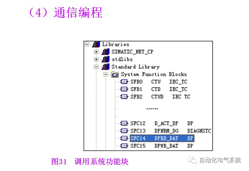
2. Application of System Functions SFC14 and SFC15 for ProfiBus Communication
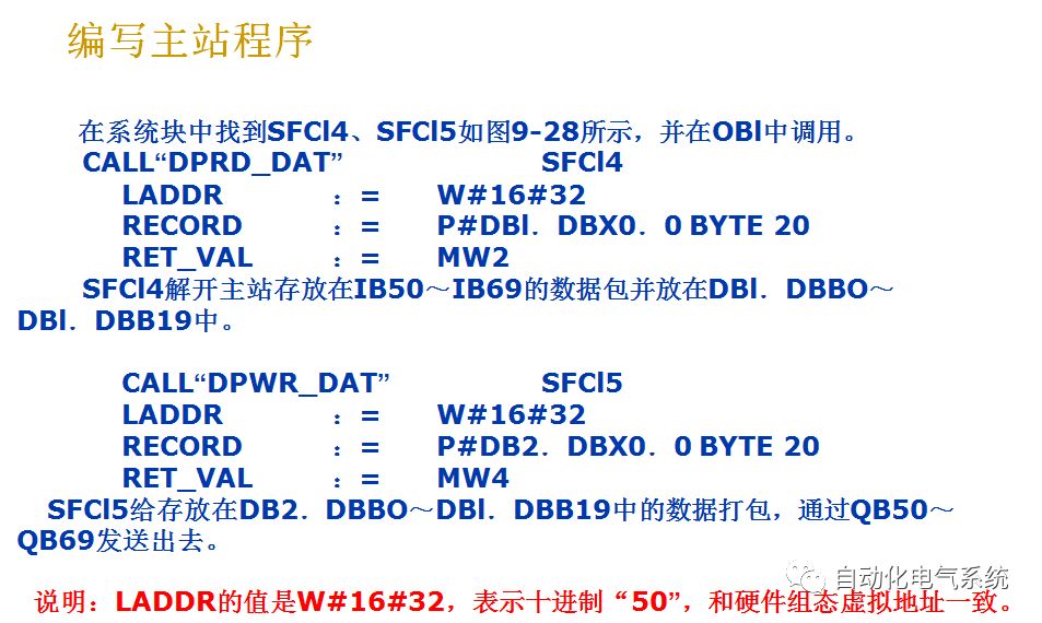
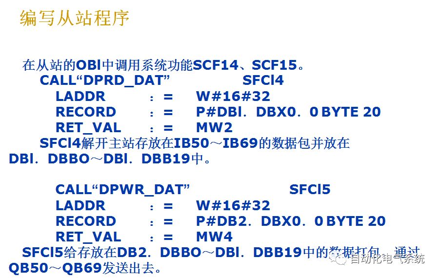
When configuring PROFIBUS-DP communication, the parameter “Consistency” (data consistency) is often seen, as shown in Figure 20. If “Unit” is selected, data communication will be sent and received in the format defined in the “Unit” parameter — by word or byte. For example, the master station sends 20 bytes in byte format, and the slave will receive and process these 20 bytes one byte at a time. If the data does not arrive in the same cycle in the slave’s receiving area, the slave may not process the data in the receiving area within one cycle. To maintain data consistency, when processing this data in one cycle, the parameter “All” must be selected; some versions use the parameter “Total length”. When the communication data exceeds 4 bytes, SFC15 must be called to pack the data, and SFC14 must be called to unpack the data, so that the data is sent and received in packets at once, ensuring data consistency. Below is an example of the application of SFC14 and SFC15, with S7-300’s 315-2DP as the master station and 313C-2DP as the slave.
(3) Network Configuration and Parameter Settings
1. Configure the hardware of the “slave” station
In STEP7, create a project for “application of system functions SFC14 and SFC15”. First, insert an S7-300 station, then double-click the “Hardware” option to enter the “Hw config” window. Click the “Catalog” icon to open the hardware directory, inserting the rack, power supply, CPU, etc., in order according to the hardware installation sequence and order number, no further explanation needed.
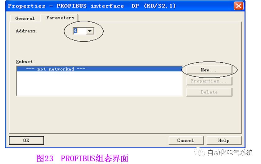
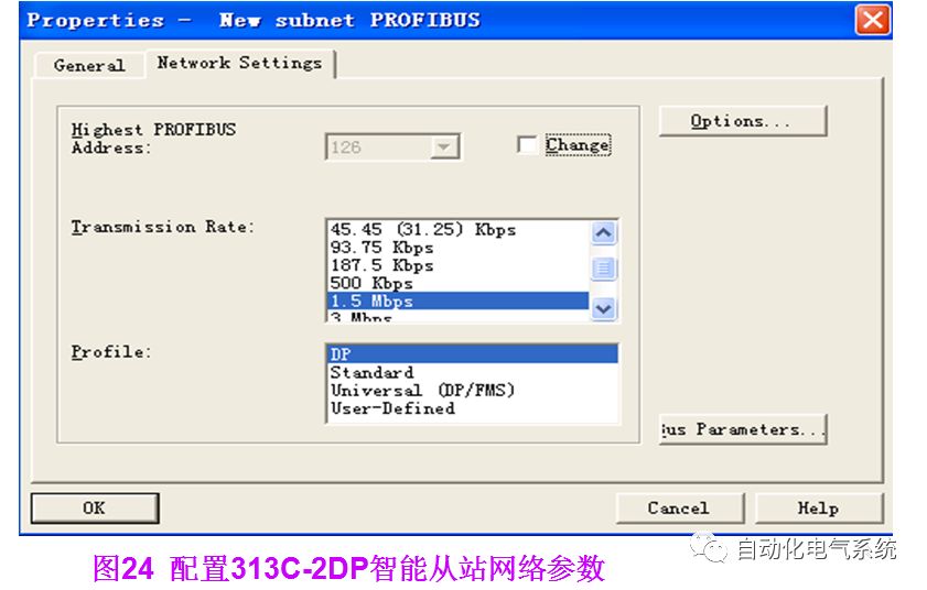
When inserting the CPU, the PROFIBUS configuration interface will pop up, as shown in Figure 23. Click the “New” button to create PROFIBUS (1), and configure the PROFIBUS station address, which is 4 in this example. Click the “Properties” button to configure network properties, selecting “Network Settings” for network parameter settings. In this example, the transmission rate of PROFIBUS is set to “1.5Mbit/s”, and the protocol is “DP”, as shown in Figure 24.
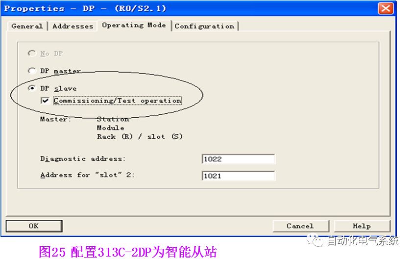
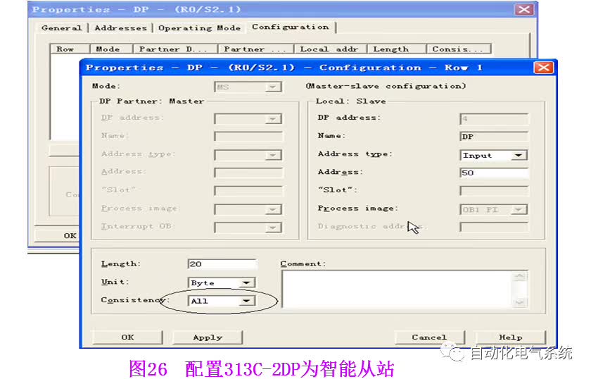
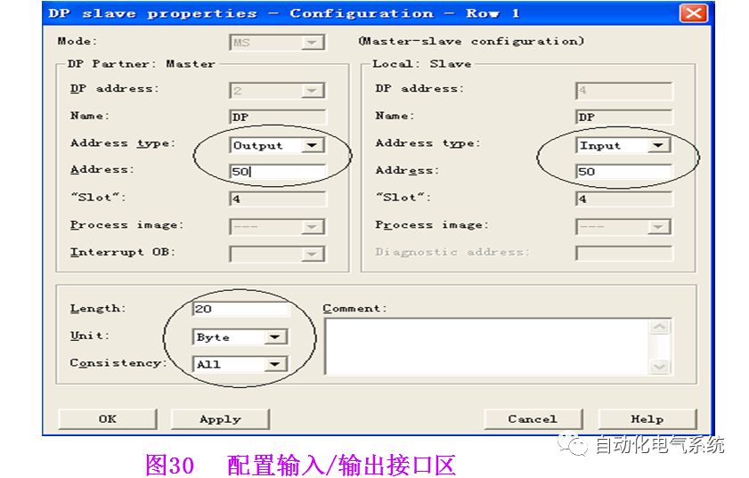
Double-click the “DP” item under CPU 313C-2DP, and the properties menu for Profibus-DP will pop up, as shown in Figure 25. In the network properties window, select the “Operating Mode” menu, and activate the “DP slave” operation mode. If the selection box below is activated, the programmer can program the slave, meaning this interface can act as a DP slave while also monitoring the program. The diagnostic address is 1022, and the default value can be selected. Select the “Configuration” tab, click the “New” button to configure the communication interface area, for example, input area IB50 to IB69 totaling 20 bytes, and select “Consistency” property as “All”, as shown in Figure 26.
In this example, the communication interface area of the slave is configured as input IB50 to IB69 and output QB50 to QB69. After clicking the “Apply” button to confirm, several rows of communication data can be added. The total size of the communication area depends on the CPU model.
(2) Configure the hardware of the “master” station
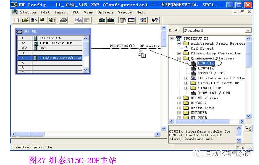
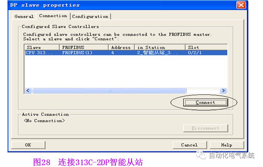
In the same way, configure the S7-300 master station, setting the PROFIBUS-DP station address to 2 and selecting the same PROFIBUS network as the slave, see Figure 27. Then open the hardware directory, select the “PROFIBUS-DP” → “Configuration Station” folder, select CPU31X, and connect it to the DP master station system’s PROFIBUS bus. At this point, the “DP-slave Properties” will automatically pop up, and in the “Connection” tab, select the already configured slave, see Figure 28.
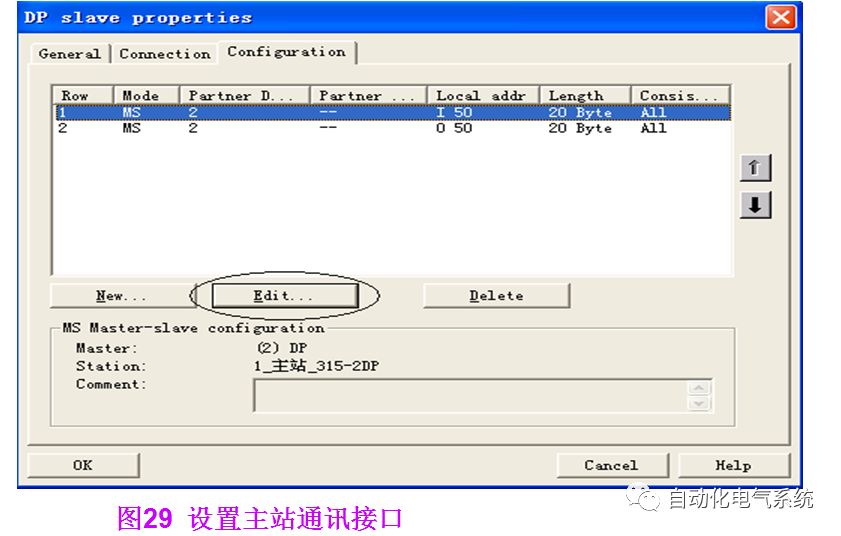
Then click the “Configuration” tab, and click “Edit” to set the communication interface area of the master station, as shown in Figure 29. The output area of the slave corresponds to the input area of the master station, and the input area of the slave corresponds to the output area of the master station. In this example, master station QB50 to QB69 corresponds to slave IB50 to IB69.
After configuring the communication interface area, download it to CPU315-2DP. To avoid network failure due to power failure at a certain station, organization blocks OB82, OB86, OBl22 should be written in S7-300.
3. Profibus Communication Between S7-300 PLCs
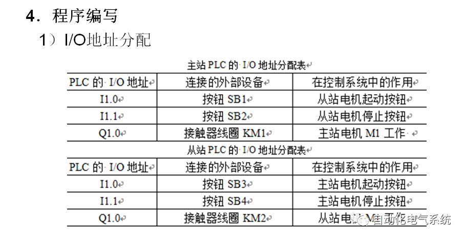
1. Control Requirements
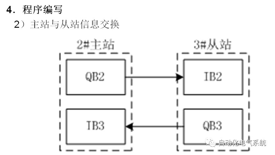
Using Profibus-DP communication method to complete the information exchange and control functions between S7-300 PLCs. The requirements are as follows:
1) The master station controls the operation and stop of the slave motor;
2) The slave controls the operation and stop of the master motor;
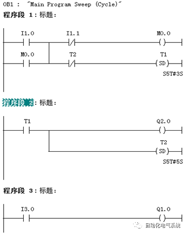
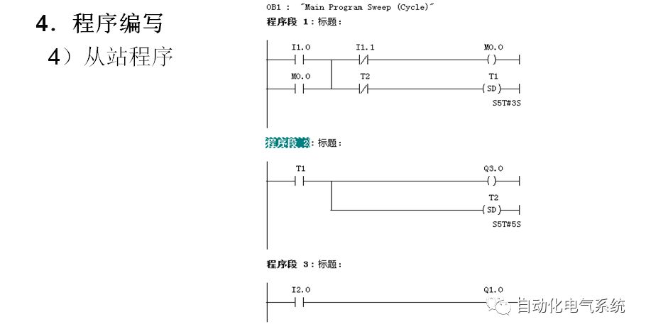
3) Press the start button for 3 seconds, the motor runs, and then stops after running for 5 seconds, and continues running after 3 seconds, repeating this cycle.

Welcome to share and follow, thank you!!!


Progress together with hundreds of thousands of robot engineers
▼

Only a follow away from becoming an industrial robot master
Guided Vehicle Robot Academy, cradle of robot engineers