The S7 protocol is the standard protocol used for communication between SIEMENS S7 series products. Its advantage is that both communication parties can establish a communication connection through the S7 protocol, regardless of whether they are on the same MPI bus, the same PROFIBUS bus, or the same Industrial Ethernet. The data exchange is independent of the type of bus or network used. S7 communication can be divided into one-way communication and two-way communication based on configuration. One-way communication is typically used in the following situations:
-
The communication partner cannot configure the S7 connection.
-
The communication partner cannot stop operations.
-
There is no desire to add communication configuration or programs on the communication partner’s side.
This article introduces the configuration steps for S7 one-way communication based on PROFIBUS for S7-400, aimed at achieving S7 communication between two independent projects.
Experimental environment, see Table 1.
| Serial Number | Name | Order Number |
| 1 | CR3 Rail | 6ES7 401-1DA01-0AA0 |
| 2 | PS407 | 6ES7 407-0DA02-0AA0 |
| 3 | CPU414-3 | 6ES7 414-3XM05-0AB0 |
| 4 | STEP7 V11 SP2 update5 | |
| 5 | Windows 7 SP1 |
Table 1
2. Configuration
2.1 Configure the S7-400 Site
Refer to Table 2 for configuring the S7-400 site.
| Serial Number | Description | Illustration |
| 1. | After creating a new project “S7-400 one-way”, click on “Project View”. |
|
| 2. | Double-click the “Add New Device” function under the project tree to pop up the Add New Device dialog box. |
|
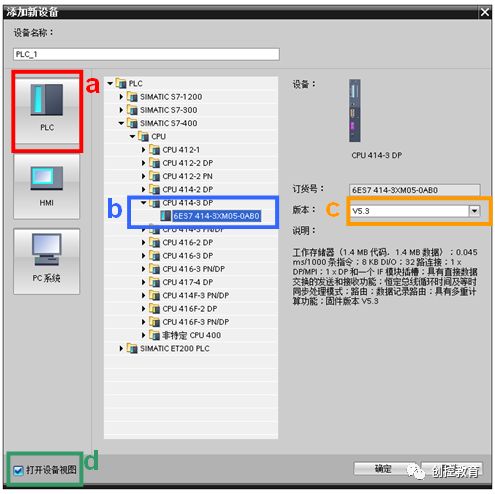
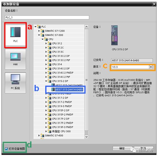
| 3. | Steps in the Add New Device dialog box:
a) Select the device type “PLC”. b) Select the CPU model to be used. c) Select the version number of the CPU to be used. d) Check the “Open Device View” option. Click the “OK” button to display the device view. |
 |
| 4. | Add a power module. | 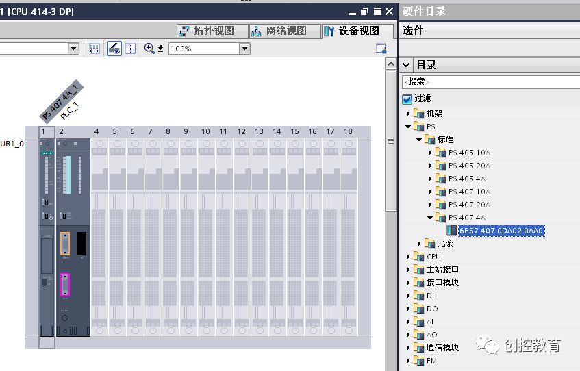 |
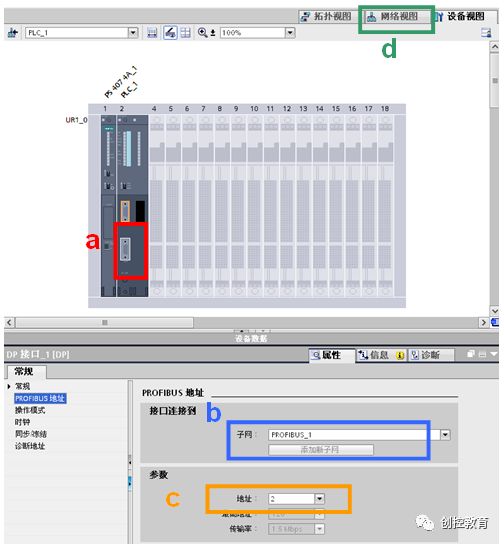
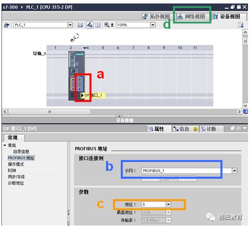
| 5. | Set the DP interface parameters in the device view:
a) Click on the DP interface of the S7-400 CPU in the workspace. b) Add a new subnet. c) Set the S7-400 station address to 2. d) Switch the workspace to the network view. |
 |
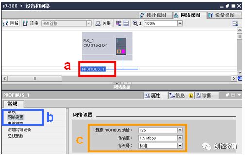
| 6. | Set the PROFIBUS bus parameters:
a) Click on the PROFIBUS_1 bus in the workspace. b) Select the “Network Settings” tab in the properties window. c) Set the transmission rate to 1.5Mbps, identifier to standard, and maximum PROFIBUS address to 126. |
|
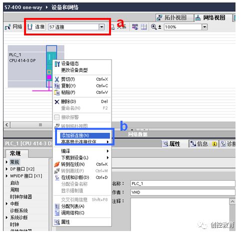
| 7. | Create an S7 connection:
a) Click the “Connect” icon in the toolbar, and select S7 connection from the dropdown. b) Right-click on the CPU and select “Add New Connection” from the popup menu, then the “Create New Connection” dialog box appears. |
 |
| 8. | In the Create New Connection dialog box, make the following settings:
a) Confirm that the connection type is S7 connection. b) Set the local interface to be used, here the interface is PLC_1, DP interface_1 (R0S2). c) Set the connection ID, here it is 1. d) Check the “Active Establish Connection” checkbox. Click the “Add” button to add the new connection, and click the “Close” button to close the Create New Connection dialog box. |
|
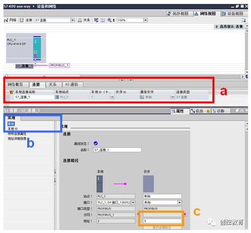
| 9. | Expand the network view list area and set the S7 connection parameters:
a) Click on “S7_Connection_1” in the list area. b) Select the “General” tab in the properties window. c) Set the partner address, here it is 3. |
 |
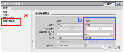
| 10. | a) Select the “Address Details” tab in the properties window.
b) Select the rack number and slot number of the partner PLC; in this example, the communication partner is S7-300, so the rack number is 0, and the slot number is 2, TSAP is 03.02. Note: For Profibus-S7 communication: · If the communication partner is S7-300, TSAP is 03.02. · If the communication partner is S7-1200/1500, TSAP is 03.01. · If the communication partner is S7-200, TSAP is 03.00. |
 |
| 11. | a) Click on the PLC_1 site in the workspace.
b) Click the compile icon to compile the configuration. c) Click the download icon to download the configuration to the CPU. |
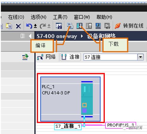 |
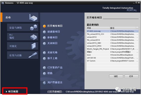
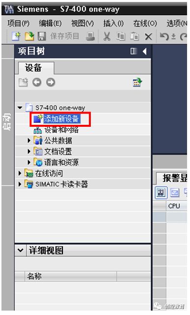
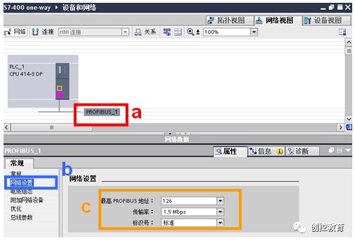
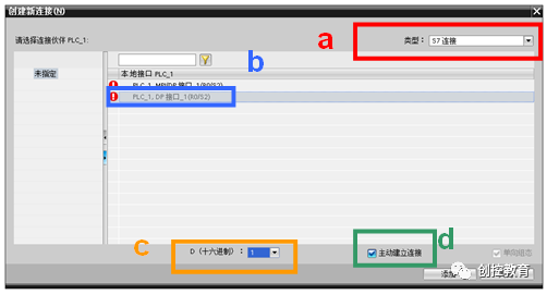
Table 1
2.2 Configure the S7-300 Site
Refer to Table 3 for configuring the S7-300 site.
| Serial Number | Description | Illustration |
| 1. | After creating a new project “s7-300”, click on “Project View”. | 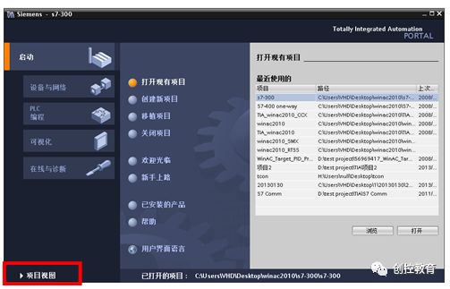 |
| 2. | Double-click the “Add New Device” function under the project tree to pop up the Add New Device dialog box. | 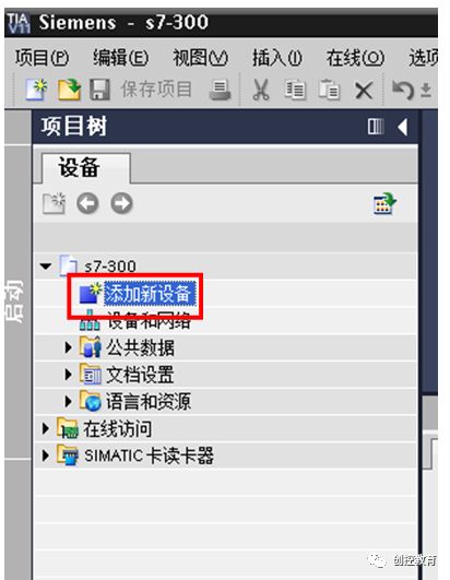 |
| 3. | Steps in the Add New Device dialog box:
a) Select the device type “PLC”. b) Select the CPU model to be used. c) Select the version number of the CPU to be used. d) Check the “Open Device View” option. Click the “OK” button to display the device view. |
 |
| 4. | Set the DP interface parameters in the device view:
a) Click on the DP interface of the S7-300 CPU in the workspace. b) Add a new subnet. c) Set the S7-300 station address to 3. d) Switch the workspace to the network view. |
 |
| 5. | Set the PROFIBUS bus parameters:
a) Click on the PROFIBUS_1 bus in the workspace. b) Select the “Network Settings” tab in the properties window. c) Set the transmission rate to 1.5Mbps, identifier to standard, and maximum PROFIBUS address to 126. |
 |
| 6. | a) Click on the PLC_1 site in the workspace.
b) Click the compile icon to compile the configuration. c) Click the download icon to download the configuration to the CPU. |
|
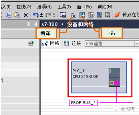
Table 3
3 Communication Connection
As shown in Figure 3-1, use the RS485 bus connector to connect the X2 interface of CPU414-3DP and the X2 interface of CPU315-2DP using the standard PROFIBUS cable.
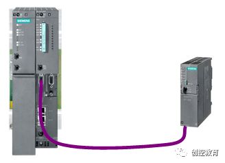
Figure 3-1: Schematic Diagram of DP Communication Connection Between CPUs
4 Communication Programming
Since one-way communication is configured for S7, programming only needs to be done on the side that configures the S7 network connection. Therefore, in this example, programming is only needed in CPU414-3DP to call the system function blocks SFB14/SFB15, as shown in Table 4.
Serial Number Description Illustration 1.
Expand the project tree, double-click on the program block Main[OB1], and open OB1 in the workspace.
 2.
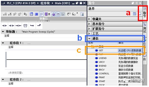
2.
a) Open the instruction task card.
b) Expand the communication instructions.
c) Select the GET instruction and drag it to program segment 1, following the prompt to add background data block.
3.
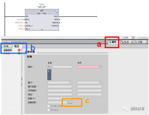
Expand the inspection window, select the “Properties” tab.
a) Click on the GET function block in program segment 1.
b) Select the “Configuration” tab in the inspection window, and click on “Connection Parameters”.
c) Click the “…” button after “Connection Name” to select the connection to be bound in the “Connection Overview” dialog box.
 4.
4.
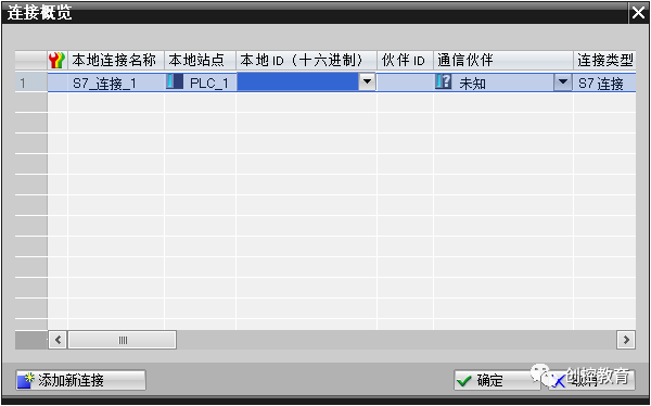
Select the connection to be bound to the function block in the Connection Overview dialog box; here it is “S7_Connection_1”, and click the “OK” button to complete the connection selection.
5.
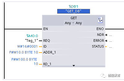
Set parameters for the GET function block:
· REQ: Control parameter request, activates the data exchange function on the rising edge; here it is M0.0, and the system automatically assigns the symbolic name “Tag_1”.
· ADDR_1: Pointer to the area to be read on the communication partner CPU, which is P#M10.0 BYTE10.
· RD_1: Pointer to the area on the local CPU used for writing the read data, which is P#M100.0 BYTE 10.
Note: The result of calling this function block is that with each rising edge of REQ, the current data values of the communication partner MB10 ~MB19 are read and saved to the local MB100~MB109 area.
 6.
6.
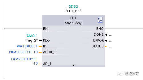
Repeat steps 2~4 to configure the PUT function block and set parameters:
· REQ: Control parameter request, activates the data exchange function on the rising edge; here it is M0.1, and the system automatically assigns the symbolic name “Tag_2”.
· ADDR_1: Pointer to the area on the partner CPU used for writing data, which is P#M20.0 BYTE10.
· SD_1: Pointer to the area on the local CPU that contains the data to be sent, which is P#M200.0 BYTE 10.
Note: The result of calling this function block is that with each rising edge of REQ, the current data values of local MB200~MB209 are written into the communication partner’s MB20~MB29 address area.
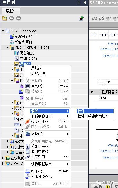
 7.
7.
Right-click on the program block under the project tree, and select “Compile” -> “Software” in the popup dialog.
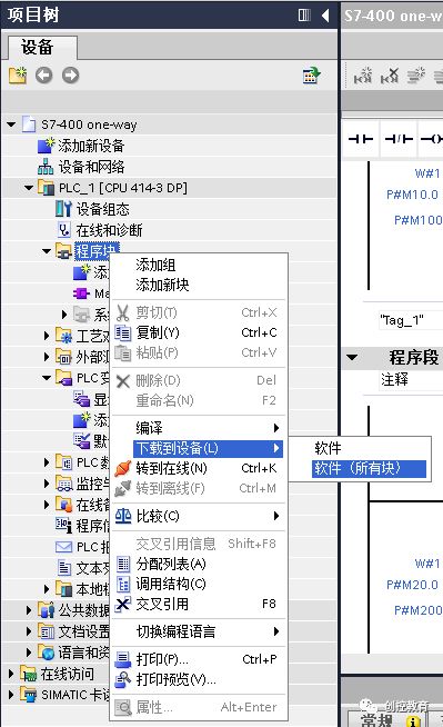
8. Right-click on the program block under the project tree, and select “Download to Device” -> “Software (All Blocks)” in the popup dialog.
(Content sourced from the internet, copyright belongs to the original author)
Disclaimer: If there are copyright issues, please contact for removal! No person or organization shall bear related legal responsibilities.