Please follow the WeChat subscription account “Finger Motorcycle” to read the latest information on motorcycle maintenance and repair. Search for ID mscmoto directly in WeChat to follow!

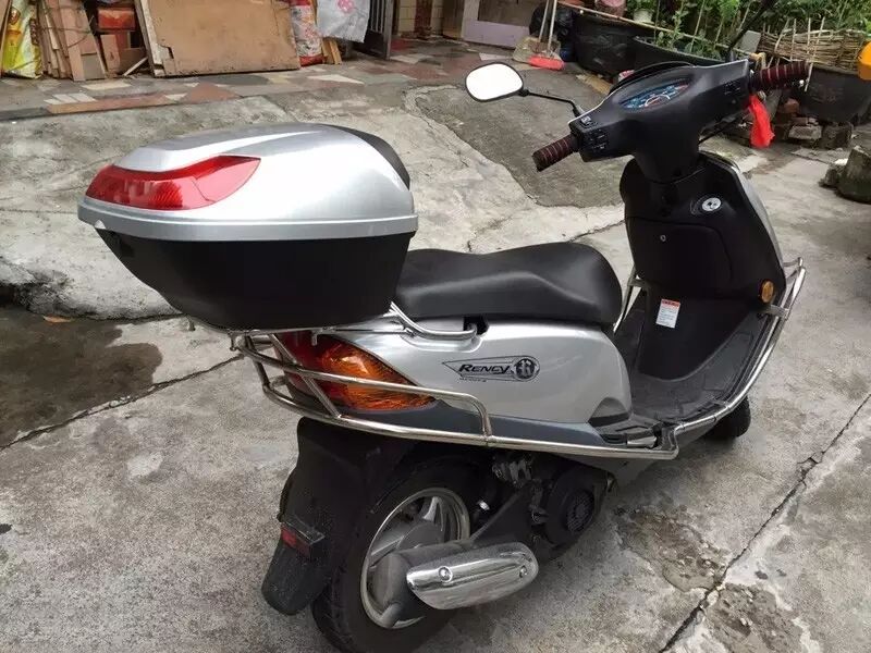
The repair process for this motorcycle began ten days ago. A customer came to the shop asking for help with an EFI motorcycle that had no spark from the high-voltage ignition system. The model was Suzuki YunCai.
I informed him that the ignition system of EFI motorcycles is closely linked to the ECM, and that the ignition module rarely fails and should not be replaced casually. I suggested checking the peripheral circuits of the motorcycle. I had previously seen a post by Brother Haifeng on Motorcycle China about the same model, and learned about the wiring of the entire vehicle from his post, which saved me a lot of trouble. Long live sharing! Similarly, I will share the repair process today.
I asked the customer to first check the anti-theft resistor and then the tilt sensor to see if there were any issues.
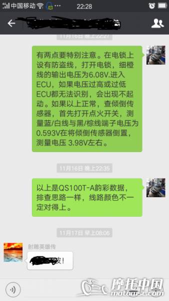
One day later, the customer informed me that he could not find the anti-theft resistor on the motorcycle and did not know which part was the tilt sensor. It seems that having a recipe without the skills does not yield good results!
After several days, the customer brought the motorcycle to my shop.
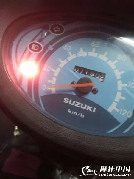
Upon turning on the ignition, I noticed that the F1 light on the dashboard was flashing continuously.
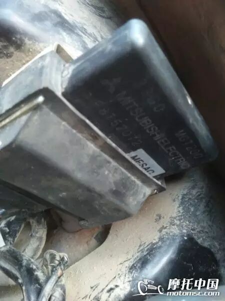
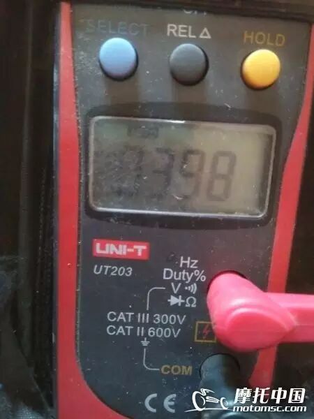
I removed the front panel and checked; it was a Mitsubishi system. I inspected the ignition lock, which had four wires: red, orange, light yellow-orange, and brown. In fact, only three wires were functional, with the brown being unused. I found that the orange wire had output voltage, but the light yellow-orange wire had no voltage.
Upon removing the ignition lock, I found it very dirty. Thick dust covered the anti-theft resistor, but it could not escape my keen eye.
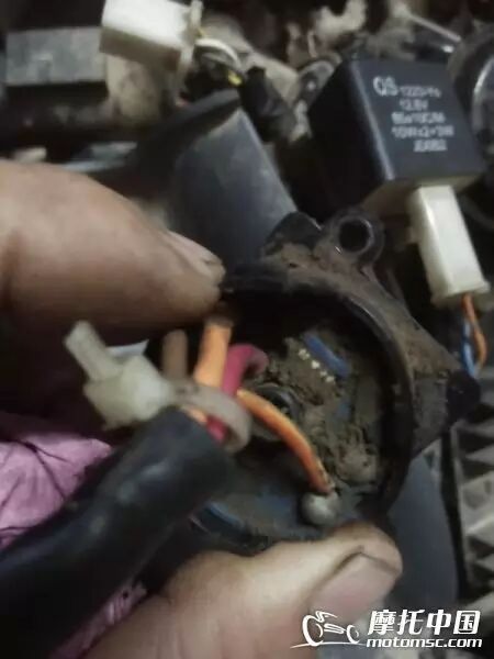
The color bands on this resistor were red, black, brown, and silver. I could not find a similar resistor on an old charger, so I directly replaced it with a 1K resistor. After reassembling the motorcycle, the high-voltage ignition system produced a spark.
However, it still could not start successfully. During the start attempt, it felt like it was struggling to ignite. Based on experience, I suspected it was a fuel issue. As we all know, relying on experience can sometimes lead you in circles, so it is essential to develop a habit of scientifically diagnosing issues and letting data speak!
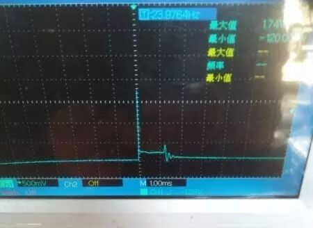
I connected the oscilloscope and first checked the secondary ignition waveform. The breakdown voltage was 10K, the combustion time was 700µs, and the jump voltage was 3500V, which was somewhat high, and the oscillation wave was a bit low.
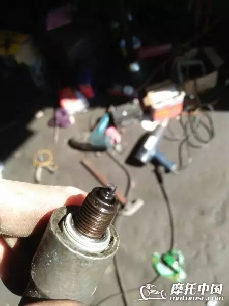
I removed the spark plug for inspection and found it very dry with a large gap. I scraped off the carbon buildup on the electrode edge, readjusted the gap, and after reassembling the motorcycle, I attempted to start it five times but still could not get it to start. I also noticed that the battery voltage was insufficient, so I had to charge it while using it. Next, I checked the fuel injection pulse width during starting, which met the starting requirements, so that part was fine.
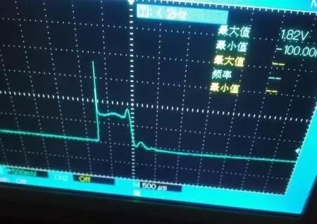
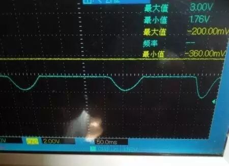
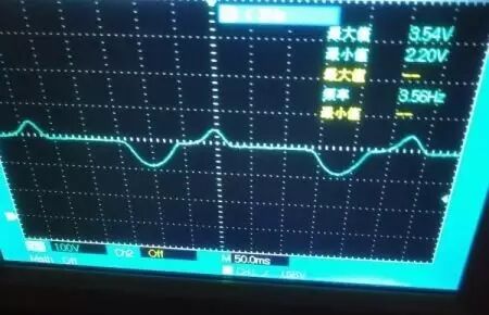
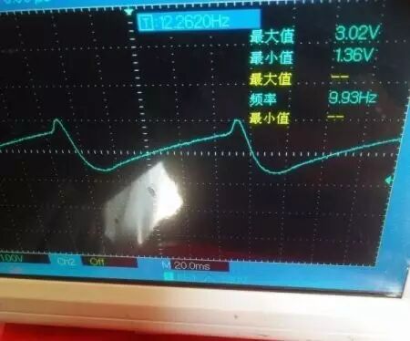
Next, I looked at the pressure waveform, which had a minimum voltage of 1.76V, somewhat high, and the waveform shape suggested a lean air-fuel mixture.
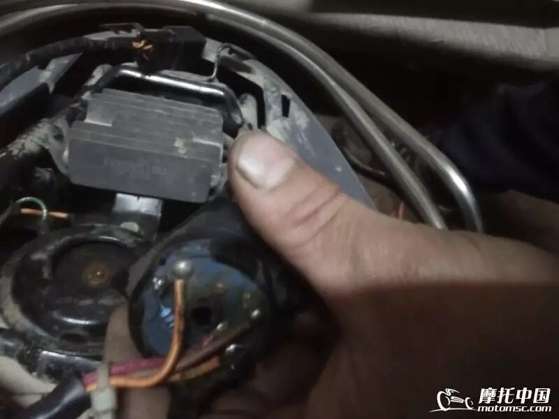
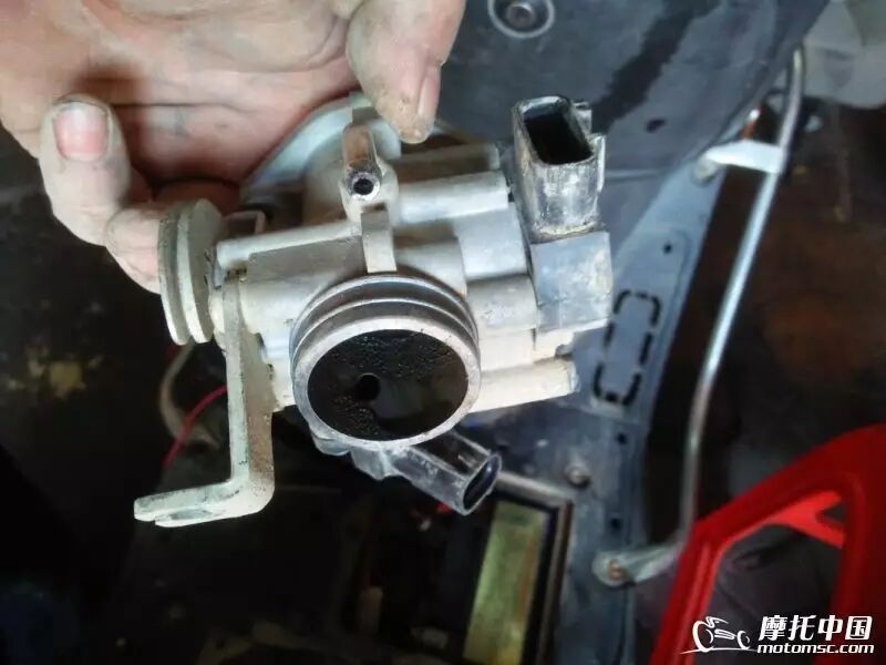
I checked the D-pump and confirmed that fuel was being sprayed. After removing the air filter assembly, I found the throttle plate was very dirty, so I checked the TPS, which used a two-in-one sensor from the Three Kingdoms.
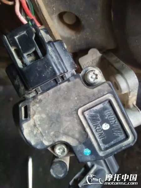
Inside the connector, from left to right, there are five letters: V, T, G, M, A. After checking, V is the 5V power supply, T is the TPS signal, G is the ground, and M and A are for the intake temperature sensor. When heating the intake port with hot air, the voltages of M and A changed, and when performing the throttle action, the TPS showed a voltage change from 0.5V to 3.6V.
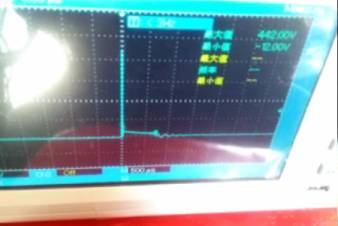
The possibility of the throttle plate being stuck was low. After cleaning, I measured the starting waveform again, and this time the maximum value was different, exceeding normal atmospheric pressure.
In the past, when measuring carbureted motorcycles, if the maximum value exceeded normal atmospheric pressure during starting, it was generally determined that there was a leak in the intake valve. Therefore, I removed the cylinder head to check the valve clearance, which was normal. Since I did not disassemble the outer casing, it was difficult to attach the compression gauge. By hand, I turned the flywheel and felt that the compression pressure was not significantly abnormal, so I did not rule out that the EFI motorcycle’s waveform was caused by the solenoid valve.
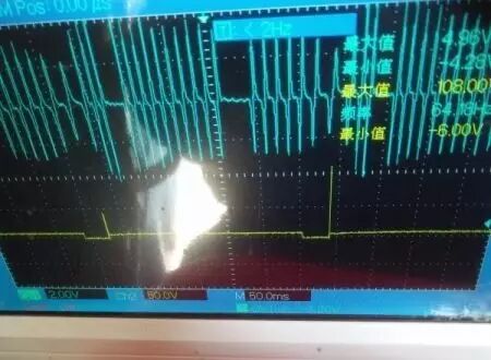
Next, I looked at the primary waveform and found that during starting, the primary waveform’s combustion time was sometimes present and sometimes absent.
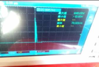
I hesitated for a moment but still trusted the waveform results displayed by the oscilloscope, as I could not think of any other reasons to refute it. At this point, I removed the spark plug again and saw that the electrode was soaked with gasoline, flooded!
Suddenly, I realized that the slow starting speed had caused flooding, and the pressure waveform graph showed a maximum value exceeding normal atmospheric pressure, which was caused by occasional backfiring. After cleaning the spark plug and disconnecting the trigger connector, I cranked the engine a few times without the ignition and successfully started it after reassembling. After all the hassle, it turned out that replacing the anti-theft resistor had resolved the issue, but later flooding had caused the failure to start.
After troubleshooting, I wanted to review the troubleshooting scenario and turn the repair process into experience. So I unplugged the solenoid valve connector and the trigger signal, and then checked the starting waveform.
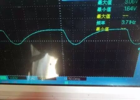 The normal voltage was 3.08V, with a maximum starting wave value of 3V and a minimum of 1.64V, similar to the starting wave measured under normal conditions for carbureted motorcycles.
This recorded repair process, although tedious, was indeed a step-by-step troubleshooting method. Those with a keen eye can always see the details, and technology progresses through practice…
Further Reading:
Tutorial | This is how I use the oscilloscope probe
Electrical System Fault Diagnosis “Twelve Methods”
Tip | DIY 5000V High Voltage Pliers for Motorcycle Repair
Special Topic | Introduction to Motorcycle DC Capacitor Ignition Systems
Finger Motorcycle
Official WeChat subscription account of Motorcycle China

WeChat ID: mscmoto

Long press the QR code to donate
Note: For detailed content, click the original text below the screen.