1. Introduction
In the production of electronic cones, it is necessary to detect a 20kHz electromagnetic navigation signal to unify the reset state of the electronic cone indicator. To reduce detection costs, the LM567[2] audio signal detection chip is used to detect the electromagnetic navigation signal. This DIP8 packaged LM567 is convenient for testing on a breadboard.
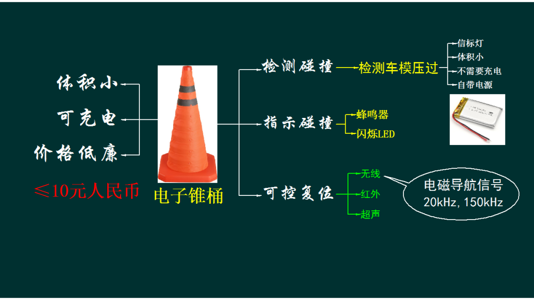
This DIP8 packaged LM567 is convenient for testing on a breadboard.

2. Basic Testing
1. Circuit Setup
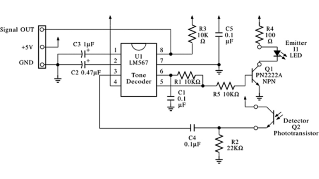
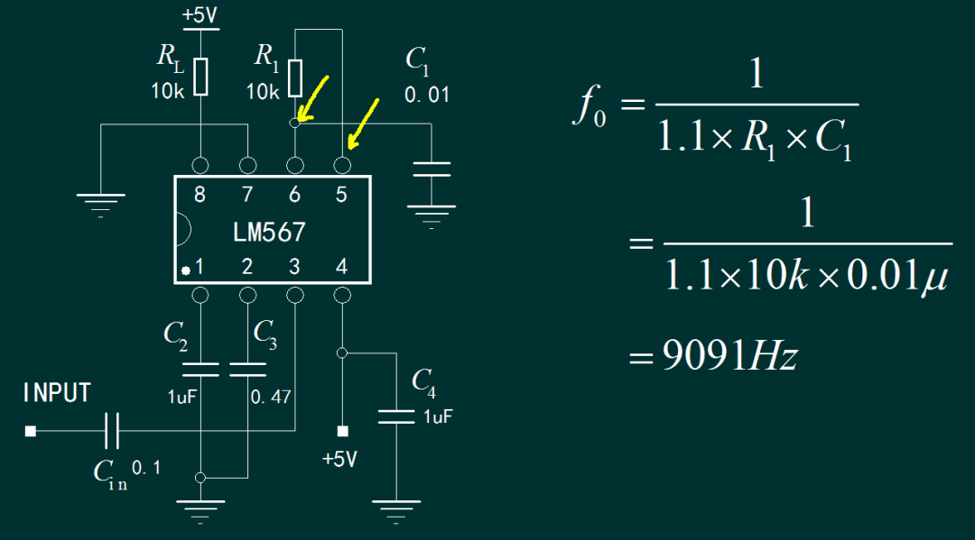
According to the LM567 datasheet, a test circuit is designed. The operating voltage is set to 5V, and the external detection signal is coupled to pin 3 of the LM567 through a capacitor. The oscillation signal of the chip can be measured at pins 6 and 5, while the output signal can be measured at pin 8. Below is the construction of this circuit on a breadboard.

▲ Figure 1.2.1 Test Circuit SchematicThe circuit components are relatively few, making it easy to build the test circuit on a breadboard. Except for the input capacitor, the other components are placed as shown on the circuit board. The basic functionality will be tested next. The operating voltage is set to 5V.

2. Test Results
After powering on, the circuit consumes about 7mA. First, using an oscilloscope, the oscillation signals at pins 6 and 5 are measured. Pin 5 shows a square wave signal, while pin 6 shows a triangular wave signal, with a frequency of approximately 10.49kHz. This indicates that the circuit is functioning properly.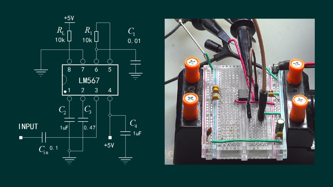

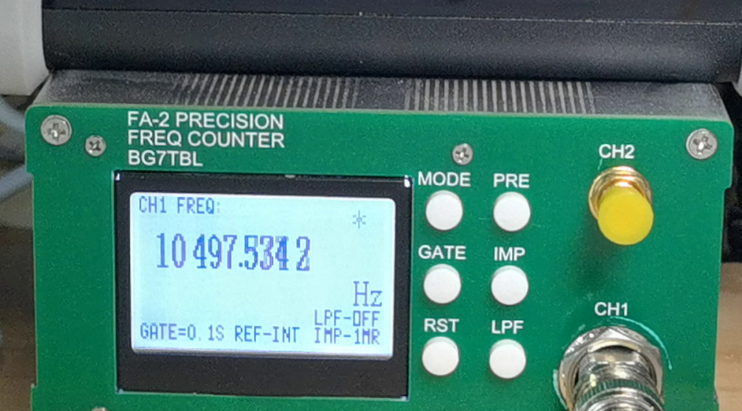
According to the LM567 datasheet, the oscillation frequency is determined by the parameters R1 and C1. Based on the parameters in the circuit diagram, the circuit’s oscillation frequency should be 9091Hz, which has a 10% deviation from the actual oscillation frequency. This is likely due to component parameter errors.
3. Signal Detection
Using the DG1062 programmable signal generator, a 10kHz sine wave with a peak-to-peak value of 1V is generated and coupled to the LM567 chip through a capacitor. The second channel of the oscilloscope measures pin 8 of the LM567, displaying the signal detection results. It can be seen that when the signal is connected to the LM567, pin 8 outputs a low level. When no signal is connected, pin 8 outputs a high level. Another phenomenon observed is that when the external signal is input, the oscillation signal of the LM567 is also locked at 10kHz. When no signal is connected, the oscillation signal of the LM567 is determined by its oscillation resistance-capacitance parameters.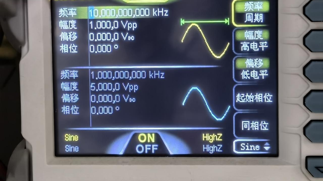
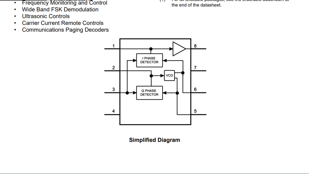
According to the internal functional block diagram shown in the LM567 datasheet, the internal oscillation circuit of the LM567 is a voltage-controlled oscillator. Under the action of the internal detection circuit, it can lock onto the external oscillation signal. Therefore, the signal detection process of the LM567 is also a process of locking onto the signal.
Next, the input signal, oscillation signal, and LM567 detection output signal will be tested. By changing the frequency of the input signal, it can be observed that between 9.5kHz and 11kHz, the LM567 can lock onto the frequency of the external input signal. Once locked, the output is low level. If it loses lock, the output is high level.
▲ Figure 1.3.1 Relationship Between Input Signal and Oscillation Signal4. External Input Signal
If the LM567 is not allowed to oscillate on its own, an external oscillation signal can be coupled into pin 6 through C1. When the amplitude of the input signal exceeds a certain threshold, a square wave signal will also appear at pin 5. The yellow square wave signal in the oscilloscope is the measured signal from pin 5. Then, another sine wave signal is input through the coupling capacitor, with a frequency difference of 0.25Hz between the two signals. Three signals are displayed here: the yellow square wave signal is the oscillation signal appearing at pin 5; the cyan signal is the sine wave signal. It can be seen that there is a frequency difference of 0.25Hz between it and 10kHz. The pink signal is the output signal from pin 8 of the LM567. It can be observed that the detected output signal fluctuates up and down, approximately 0.25Hz.

▲ Figure 1.4.1 Relationship Between External Input Signal and Detected SignalOnly when the two signals are completely in phase will the output signal be low level. This shows that the LM567 relies on its internal phase-locked loop oscillation circuit to stably detect the input signal.
This article provides a preliminary test of the LM567 audio signal detection function. Utilizing its internal phase-locked loop oscillation, it can detect signals within a specific frequency range. This frequency range is determined by the external resistance-capacitance parameters of the LM567 phase-locked loop oscillator. It cannot operate under external input signal conditions.