Abstract—This article introduces a fault injection library for SystemC/SystemC AMS, which can be used to dynamically integrate fault structures into any SystemC/SystemC AMS description. The injection is achieved by dynamically reconnecting the netlist at the start of the test case execution without altering the DUT model itself. This method has been successfully validated on a battery management system (BMS) model. Furthermore, the proposed fault library’s benefits for hardware-in-the-loop (HiL) systems were demonstrated and discussed during laboratory validation for the same system.Keywords—validation, verification, SystemC AMS, fault injection, HiL, hardware accelerationI. IntroductionSystems composed of analog and digital hardware as well as embedded software are becoming increasingly complex, as physical environments must be considered during the validation and verification phases. However, validation requires not only testing normal behavior but also examining the behavior when components fail.This ensures not only functional requirements are met but also safety requirements. Validation tools and methods must support the design of systems that are functionally correct, robust, and safe.In particular, the automotive industry expects solutions to comply with the ISO 26262 functional safety standard. The proposed method can be applied to the design process of relevant systems.The simulation approach based on SystemC/SystemC AMS is a good choice for validating nominal behavior. It guarantees high simulation speed while maintaining adequate accuracy. Software development aspects can be incorporated into the design and validation process. This method also closes the bridge to hardware-in-the-loop (HiL) simulation, thus also leading to laboratory validation.So far, little effort has been invested in improving considerations for faults and appropriate fault behavior modeling methods. Therefore, this paper presents a new approach to inject fault behavior into the SystemC/SystemC AMS description of nominal behavior without changing the model or netlist. Thus, the main advantage of this solution is that for various faults, no modifications are required to the SystemC/SystemC AMS description provided for normal conditions. Fault behavior can be handled at the test scenario level.During the IKEBA* project, the potential of methods related to the specification phase of the battery management system was investigated and further tested in a HiL environment.State-of-the-art fault injection methods typically integrate fault behavior or fault structures directly into the model used as the DUT. For a given test case, either normal or fault behavior is used. The disadvantage of this approach is that there is no clear distinction between functional descriptions and test descriptions. On the other hand, there is a risk of inconsistency between functional and fault behavior.This paper is organized as follows: Section II describes the requirements for the fault injection mechanism. Section III describes the proposed library for different SystemC/SystemC AMS domains and models of computation (MoC). Then, in Section IV, the library is used in conjunction with hybrid HiL simulation. Section V presents a case study based on the battery management system. Finally, Sections VI and VII summarize the paper and outline future work.II. Fault Injection RequirementsTo ensure usability across various models/systems, a generic modeling approach must be employed. This allows the fault injection library to be used for different model domains and MoCs.The fault injection method should guarantee a clear and absolute separation between the functional model (DUT) and the test description.This means that two aspects related to data management and runtime integration must be separated. Additionally, this provides the possibility of completely independent descriptions for developing the functional model (DUT), test environment, and fault description. Another key point should be the simple usability of the use case itself. Therefore, predefined and standardized interfaces must be used. Last but not least, there must be a central location for fault configurations related to a given test case.III. Proposed LibraryThe introduced fault injection library employs a layered approach. This means that fault injection can be described at different levels of abstraction. The lowest level includes injection structures, such as disconnecting signals/ports from the DUT netlist and the fault injection model. This reconnection is dynamically completed before the simulation of the relevant test case begins and does not change the DUT model itself.A. SystemC Background:The execution of SystemC applications is divided into two phases: elaboration and simulation [1]. During elaboration, a module hierarchy is created that will be simulated in the second phase.To control the different phases, the hardware description language SystemC provides callback functions.These callback functions are called by the simulator kernel and can be used to influence execution. For example, the callback function before_end_of_elaboration is called after the module hierarchy is created but before port binding is completed. Therefore, the module hierarchy can still be extended or manipulated. This language feature is used to instantiate fault structures that will be injected into the DUT hierarchy.
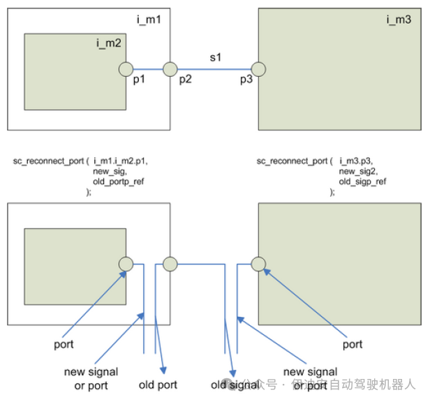 Figure 1: Reconnection method, source: COSEDA Technologies GmbH
B. Reconnection:Based on the language features described in the previous section, the design environment COSIDE1 has already provided a library function sc_reconnect_port. This function references the target port, new signal, and signal reference to return the previously connected signal. If this function is called during the before_end_of_elaboration callback, it can use the reference to insert switchable drivers.In principle, this method is applicable to all MoCs in SystemC/SystemC AMS systems with different kinds of low-level fault injection structure models. The low-level structure model represents the lowest level of abstraction of the fault injection model in the library and can be a simple multiplexer, for example, for non-conservative signals/ports. Thereafter, such a multiplexer can switch between the original driver and the new driver, such as a new source (e.g., for fixed values) or another signal from within or outside the DUT (e.g., for crosstalk).For linear networks, as one of the SystemC AMS MoCs, switchable resistors are instantiated. By using references to the original connection nodes and terminals, the resistors connect between the two. Thereafter, the resistor value can be defined by separate ports. Depending on the fault model used, additional switchable resistors and voltage sources may need to be instantiated to connect alternative sources to the target terminal. Furthermore, it must be considered that the MoC and signal types of the source and target must be the same. Figure 2 shows the low-level structures for different MoCs.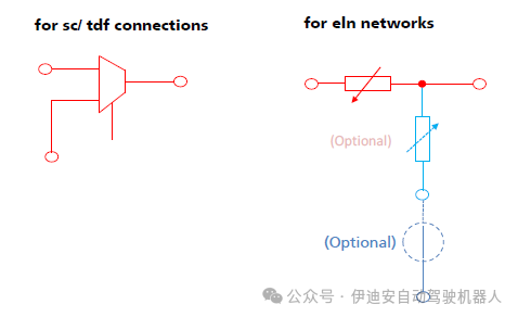
Figure 2: Low-level fault structures for different domains
C. Fault Models:The fault injection library contains many classical fault models based on the low-level injection structures introduced in the previous sections.The fault models represent the next higher level of abstraction in the library.In practice, the following classes of fault models are available: stuck-at (value or signal), crosstalk, bridging, open/short circuit, delay, and fault. Plans to extend this enumeration are underway. The following figure shows examples.
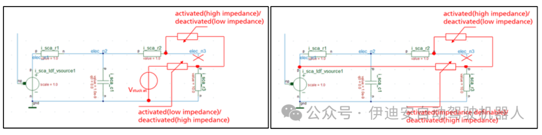 Figure 4: Stuck-at (value) and crosstalk examples for linear networks
Fault models are implemented as template classes. This means they can be used for various signal types. The data type is a template parameter that must be defined during instantiation. In contrast to the data type, the MoC type is automatically recognized by deriving from the signal/port. Therefore, the correct low-level structure is automatically selected. During the instantiation of the fault model, a set of parameters is required, which at least includes a string representing the target port name and its hierarchy. Thus, it indicates where the fault should be injected. Optionally, a second string for the new driver of the object can be provided. This new driver can also be realized by instantiating additional modules before the relevant fault model instantiation.The constructor of the fault model will call the function get_object using the above object name string. If these objects can be successfully found, this function will return a reference to the expected object. The get_object function with extended pattern matching is also part of the COSIDE design environment, allowing objects to be found in the module hierarchy by searching for their object names at runtime.The fault model crosstalk allows (especially for digital or non-conservative signals/ports) to define the logical combination type of the original driver and the new driver. The logically available combinations include WAND, WOR, ADD, SUB, REPLACE, and USER. The last one can call user functions to implement combinations.
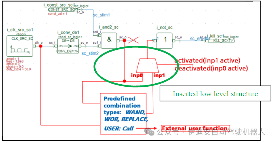 Figure 5: Logical combination types of crosstalk in non-conservative networks
D. Scenarios:The highest level of abstraction in the library is represented by scenarios. Scenarios instantiate one or more fault models and allow for their configuration. The library includes a scenario template class that can use predefined fault models. The template parameter of the scenario is the data type of the target port. Additionally, the constructor requires some parameters. The first constructor parameter includes a vector of string pairs. Since scenarios can handle multiple instances of fault models, these pairs are the target and source ports for each fault model. The second parameter is the name of the desired fault model. This parameter’s type is an enumeration that includes all predefined fault models. Additional constructor parameters may be required, such as logical combinations in crosstalk fault models. The fault scenario template includes the possibility of permanently activating fault models. Alternatively, sequences for periodically activating/deactivating fault models can be configured. Additionally, voltage scans for stuck fault models can be configured.E. Applying the Library and Stimulus Models:Creating separate SystemC stimulus modules is an effective way to apply the fault injection library to specific investigations. The sole task of such stimulus models is to instantiate and configure one or more fault injection scenarios. Additionally, the stimulus module provides activation/deactivation related to faults and optional tracing functionality. In most cases, the fault injection stimulus module is related to a specific test case. Therefore, it is recommended to create a special fault injection stimulus module for each test case that includes fault injection. Figure 7 shows an example of a fault injection stimulus model that includes crosstalk and stuck scenarios.
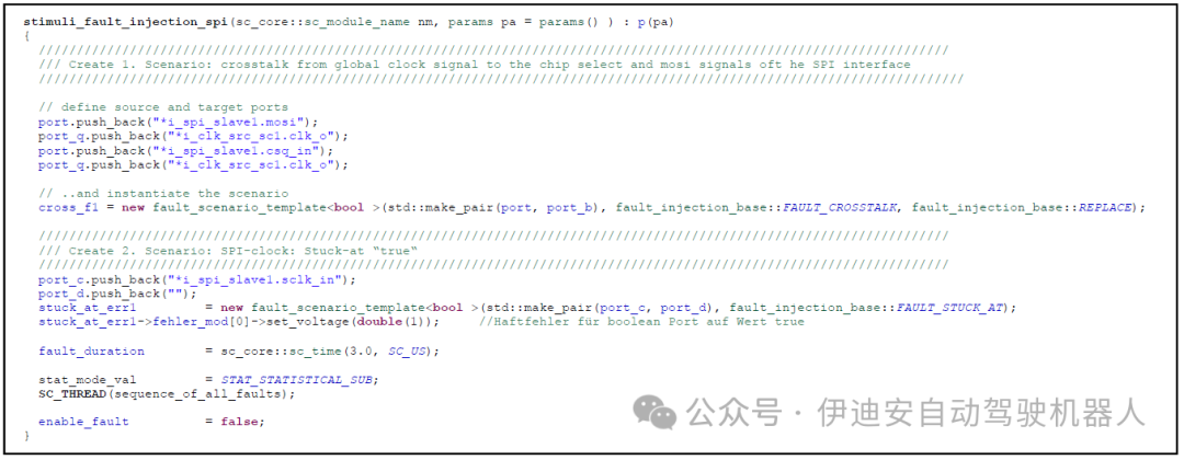 Figure 7: Example of a fault injection stimulus module that creates different scenarios
F. Activating During Test Cases:The simplest way to integrate fault injection into specific test cases is to instantiate the fault injection stimulus module described in the previous section. The activation function of the fault injection stimulus model can be called based on simulation time or triggering events to activate fault injection. The COSIDE environment supports configuring test cases using a generic method and provides automatic generation of template files (i.e., generic test case files). Typically, the activation/deactivation of fault injection is described in the stimulus_sequence section of such generic test case files.
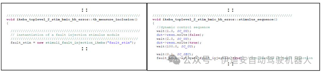 Figure 8: Instantiation and activation of stimulus fault models in a generic test case file
G. Inclusion of Statistical Aspects:The occurrence of faults in real systems may depend on various conditions, which are often unpredictable. To reproduce similar behavior, statistical methods are state-of-the-art.
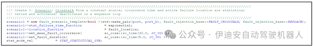 Figure 9: Example of fault injection using statistical functions from the statistical library
The statistical library introduced in [2] can be used to integrate statistical functionality into the actual version of the fault injection library. For a given test case, the time of fault occurrence can be determined simultaneously, and if multiple fault models are included, the fault location can also be determined.H. Specifics of TLM Transactions:Due to the lack of literal signals and ports, the methods described in the previous sections do not apply to TLM transactions. Instead, TLM uses so-called sockets to transmit information, which can be understood as using access functions. Therefore, fault injection for TLM transactions must be implemented in a completely different way.
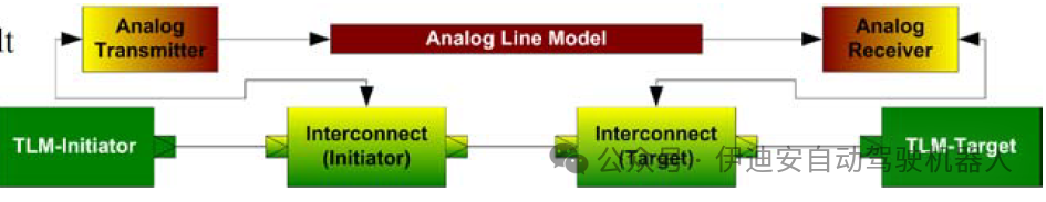 Figure 10: Example of adapter insertion, source: [3]
One feasible method for injecting faults into TLM transactions is to use so-called adapters. Such adapters represent interconnections that are automatically integrated between TLM initiators and/or TLM targets. The TLM adapter approach has been described in [3]. The advantage of these adapters is their high flexibility, which can also be used for fault injection. Special operational functionalities must be provided based on the transactions used, as the transaction content is specific to the actual transaction and its operations. On the other hand, efforts are being made to write adapters and automatically integrate them into specific TLM models. However, using tlm_generic_libraries [4] for custom TLM applications can greatly simplify this task. Using adapters to inject faults into TLM transactions is a reliable method. Other TLM methods have not yet been investigated, so they are not the focus of this paper.IV. Fault Injection During Laboratory ValidationThe fault injection mechanisms described above are not limited to virtual prototypes but can also be applied during laboratory validation and can even be reused from virtual prototypes.Through laboratory validation, we learned that testing early available components or prototypes of the system is insufficient for complete system testing.Therefore, we distinguish the following three major categories of prototypes:
- Pure Virtual – Virtual prototypes that are entirely modeled and executed by a simulator
- Real Hardware – Setups where each part of the prototype is represented by existing hardware
- Hybrid (HiL) – A mix of both, where the virtual part is executed on special hardware (HiL tester)
The requirements of this hybrid environment aim to obtain a HiL tester capable of running SystemC AMS for the model part and a hardware/software interface that ensures accurate connections of values and timing.This is discussed in detail in [7]. To compare different types of prototypes, they need to be evaluated based on the different aspects listed below:
- Debugging – Accessibility and traceability of signals for root cause analysis of errors
- Speed/Detail – Trade-off between model speed and level of detail
- Fault Injection – Possibility to manipulate expected behavior to assess system robustness
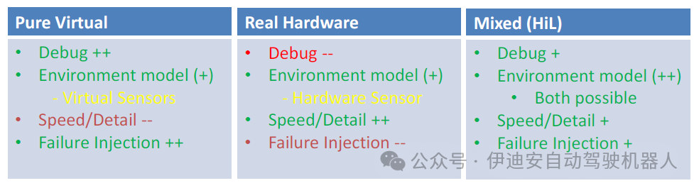 Figure 11: Comparison of different types of prototypes
The comparison results are shown in Figure 11. Thus, the table shows that virtual prototypes are the easiest to debug and always involve a trade-off between modeling detail and final simulation speed.Especially in terms of fault injection, virtual prototypes excel, as the fault injection library discussed in this paper can be used.On the other hand, hardware prototypes inherently retain every detail while maintaining full speed, but accessibility for debugging signals and internals is very limited. Their fault injection is limited to applicable locations, the resulting consequences, and deterministic repeatability. For example, locations are accessible terminals that can be cut off or shorted. Consequences may include permanent hardware damage or environmental hazards. HiL prototypes contain real hardware as well as models running on the HiL Tester.Thus, the advantages of the discussed software and hardware parts still exist, but the partitioning can vary as needed, up to the complete hardware model of the DUT. At this point, only the test bench will remain in the SystemC AMS on the HiL-Tester.To highlight the advantages of hybrid prototypes, the partitioning of the BMS case study was discussed. One scenario of the prototype is firmware development. Therefore, the control unit and its application processor are used in real hardware to run the firmware, while the environment remains in software to easily inject faults, and the firmware should be resilient. In particular, the battery cells should remain in software.Because they can cause fires or short-circuit damage, which would lead to replacements during firmware design or regression runs.This also benefits testing time, as the batteries must be charged and discharged to achieve a certain state of charge, which is not even deterministically reproducible due to the complex physicochemical reactions involved.The HiL setup also provides a real and safe environment for early versions of the firmware, as unexpected faults may also occur during firmware development.Therefore, the introduced fault injection library also aids the design process during laboratory validation and significantly increases the test coverage at this stage.V. Case Study on Battery ManagementA critical key point in the development process, especially for automotive components and systems, is ensuring their functional safety. The government-funded IKEBA project investigated the applicability of fault injection into real systems based on this theme. The foundation of this work is the system model of the battery management system created in the project. This complex system model includes not only digital and analog hardware components but also non-electrical effects of the target system and actual software applications. The battery model was created using the characteristic analysis results of real battery cells manufactured by Karlsruhe KIT.One goal of the project was to investigate whether the management software application from project partner Hella could quickly identify faults and respond appropriately, such as after a single cell failure or overheating. During the project, we decided that dynamic fault injection was the best method to accomplish this task.
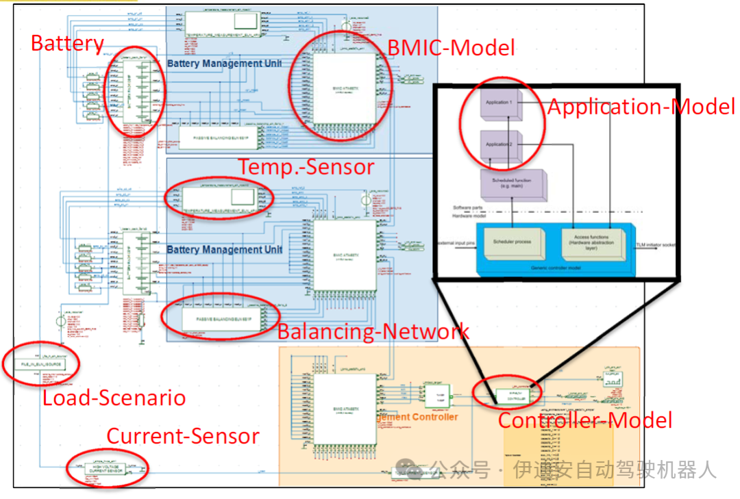 Figure 12: Top level of the battery management system model
Thus, the fault injection method was widely used in the following tasks:– Investigating the effects when battery cells exceed specified voltage or temperature ranges– Investigating communication faults in the SPI interface– Triggering dynamic load balancing– Generating special stimuli, e.g., for the internal ADC of the BMICThe following figure shows the application of the library for injecting faults into the battery pack model. This is achieved by connecting switchable resistors in series to the terminals of the battery cells. Thereafter, the relevant cell can be deactivated by setting the resistor value to high impedance. In this case, an additional voltage source in parallel with the battery cell is activated. Finally, the voltage at the battery terminals can be defined by the test case description. This description can include various scenarios such as overvoltage/undervoltage, short spikes, ramps/scans, or many other scenarios. Figure 14 shows a comparison of simulation results for normal conditions and faulty battery voltages. Test cases that include fault injection are used to check the application’s ability to detect battery faults and response times. Thus, this simple example demonstrates the high flexibility of the method.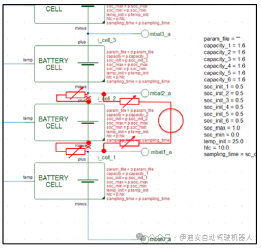
Figure 13: Fault injection in the battery pack
Overall, the system model aids in the implementation and testing phases of the BMS software. Dynamic fault injection particularly allows for accelerating the implementation of fault response procedures by providing a virtual test bench for battery boundary conditions (as described above). While the functional safety features of the IKEBA software application are far from comprehensive, the experiences gained during the project lead us to believe that a complete functional safety application would benefit from the dynamic fault injection method. The virtual system model is faster than the equivalent HiL tester setup while being more cost-effective, although it cannot fully replace HiL testing, it certainly helps reduce the HiL workload.
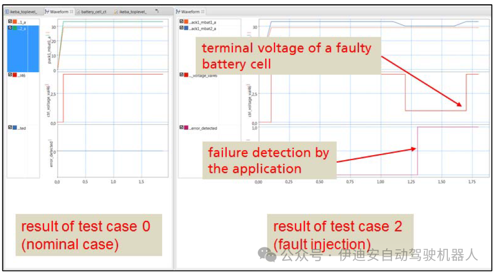 Figure 14: Comparison of nominal conditions and results of fault injection
VI. ConclusionThe presented library allows users to non-invasively inject faults into ports of different domains in SystemC AMS (including normal SystemC domains). Thus, the normal test bench includes an additional SystemC model that dynamically reconnects the DUT to include faults while also providing control handles for it. The library has been successfully used to inject faults into different parts of the battery management system (BMS) developed during the IKEBA research project.VII. Future WorkAlthough the library has proven successful for different SystemC AMS projects, the authors hope to continue efforts to improve its applicability. The library should be easy to use and integrate, for example, into existing UVM-SystemC environments [8]. Thus, it can provide additional or extended test sequences, leading to more comprehensive test runs and improving verification and validation coverage. Another focus is the traceability of injected faults and their propagation throughout the DUT.AcknowledgmentsWe thank former Fraunhofer-EAS colleagues Thomas Uhle and Karsten Einwich for their previous activities.Authors:Thomas Markwirth, Fraunhofer IIS – Design Automation Division – EAS, Dresden, GermanyPaul Ehrlich, COSEDA Technologies GmbH, Dresden, GermanyDominik Matter, Hella Aglaia Mobile Vision GmbH, Berlin, GermanyTranslation: AnneProofreading: MikeThis article is based on the Creative Commons text sharing protocol: https://creativecommons.org/licenses/by-sa/4.0/
REFERENCES
[1] IEEE Computer Society, 1666-2005 IEEE Standard SystemC Language Reference Manual
[2] T.Markwirth, J.Haase, K.Einwich; Statistical Modeling with SystemC-AMS for Automotive Systems; FDL’08; 2008
[3] S.Schulz, J.Becker, T.Uhle, K.Einwich, S.Sonntag; Transmitting TLM transactions over analogue wire models; Design Automation and Test in Europe (Date’10) conference; March 2010
[4] T.Markwirth; Entwicklung einer SystemC Modellbibliothek zur Transaktions-Level-Modellierung (TLM) für den Konzeptionsentwurf von Systemen der Automobilelektronik; Diplomarbeit TU-Dresden; 2011
[5] Accellera Systems Initiative, SystemC AMS 2.0 Standard, http://www.accellera.org/downloads/standards/systemc.
[6] P. Ehrlich, T. Nguyen, T. Vörtler, “UVM-SystemC based hardware in the loop simulations for accelerated Co-Verification”, Design and Verification Conference & Exhibition (DVCon Europe), October 2015.
[7] Accellera Systems Initiative, Standard Universal Verification Methodology (UVM), http://www.accellera.org/downloads/standards/uvm/.
[8] M. Barnasconi, F. Pêcheux and T. Vörtler, “Advancing system-level verification using UVM in SystemC”, Design and Verification Conference & Exhibition (DVCon), March 2014