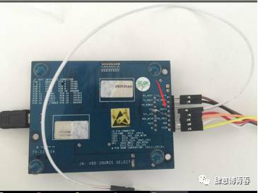
1:Tool Preparation, Test Board, Dupont Wires, and Adapter Board
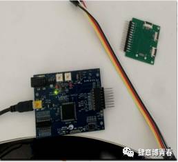
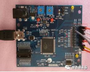
Label 1 is the adjustable sliding resistor to adjust the VDD and VDDIO voltage
Label 2 is the interface connected to TP
2 Interface Definition:
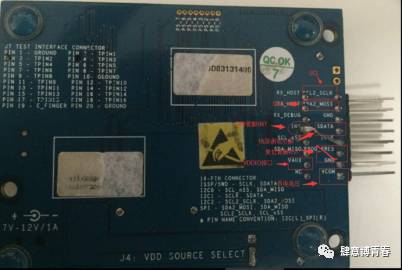
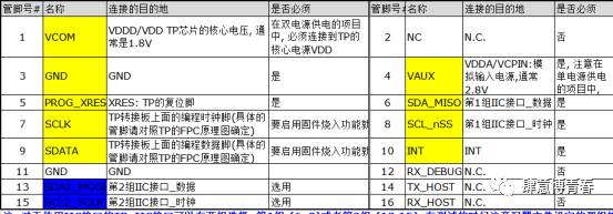
When wiring, follow the above definition and leave VDDIO unconnected.
Note:
1): For TP using the IIC interface, there are two sets of options for the IIC interface: Set 1:(6, 8) or Set 2:(13,15). During testing, ensure that the selected configuration matches the one actually used.
2): For the INT and SCLK multiplexed IC pins, the INT and SCLK on the test board need to be shorted.
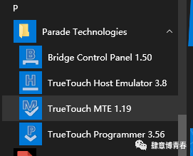
3 Install the Programming Software
After installation, you can find the Cypress folder in the start menu, which contains 3 software applications (except for TrueTouch host Emulator 3.8, which is not included).
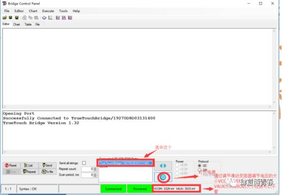
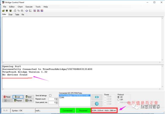
4.Open the Bridge Control Panel Software
Open the software, click the power switch button in the software, and adjust the required VDD and VDDIO values by rotating the resistor.
Ignore the VDDIO pin if it is not present.
5 . Connect the test board and adapter board to the CTP and then click list to display the I2C address.(Provided that the TP has already been programmed with firmware, the I2C address can be found. If not programmed, the list address cannot be displayed.)
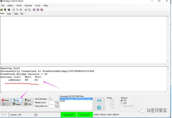
If the following situation occurs, please check if the interface definition and voltage values are correct.
6.After the IIC connection is established, close the Bridge Control Panel software and find the TrueTouch MTE 1.19 installation directory.
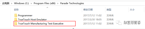
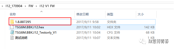
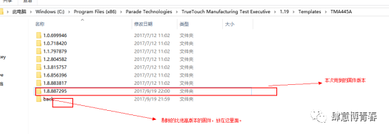
Find the Templates folder and the TMA445A folder and copy the firmware 1.8.887295
to the path
C:\Program Files (x86)\Parade Technologies\TrueTouch Manufacturing Test Executive\1.19\Templates\TMA445A
Note: For 64bit OS, the path is \Program Files (x86)\Parade Technologies\TrueTouch Manufacturing Test Executive\1.19\Templates\TMA445A
For 32Bit OS, the path is \Program Files\Parade Technologies\TrueTouch Manufacturing Test Executive\1.19\Templates\TMA445A
Copy the firmware package provided by us into the TMA445A folder.
Note: If there are multiple versions of firmware in the original path, and the version number is larger than the one we provided, you need to remove the higher version files (All opened original files are as follows:).

Since our version number is 1.8.887295, you need to remove 1.9.889091 and update after that:
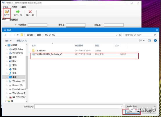
Open TrueTouch MTE 1.19
It will automatically open the add folder; if it doesn’t appear, click the open button to select the test file.Cfg format file to open.
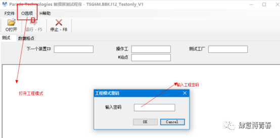
7.Click Options → Project Mode → Enter Password
Cypress: TrueCypressTouch, Parade: TrueTouchRocks
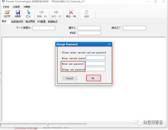
To facilitate testing, you can also modify the project password:
Click Options → Change Password , you can modify the password, with a minimum of one character.
9, Programming IC and Testing
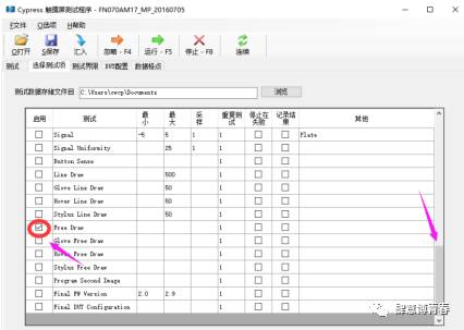
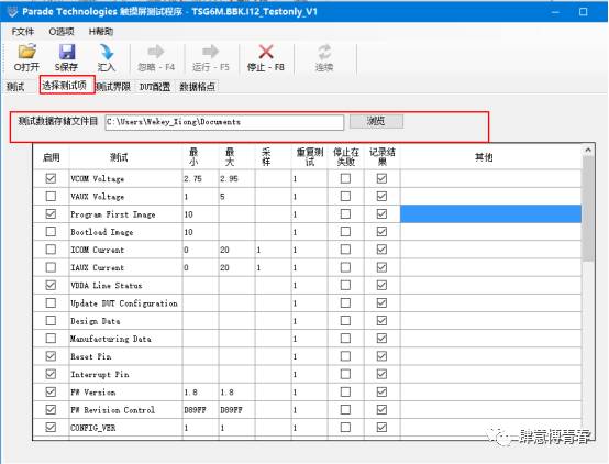
1, Configure the test information
Click to select the test option with a checkmark in front of program first image , and in the program first image corresponding
to the “Others” section, right-click and select browse, as shown below:
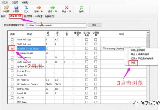
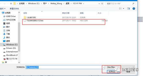
Select the programming .hex file provided by us.
Scroll down using the right scrollbar and check the box in front of Free Draw.
2.For the hardware part, short the INT and SCLK pins on the main board.
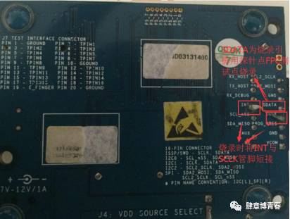
Connect the SDATA pin with a separate Dupont wire.
Connect the other end to the probe point FPC exposed test point.
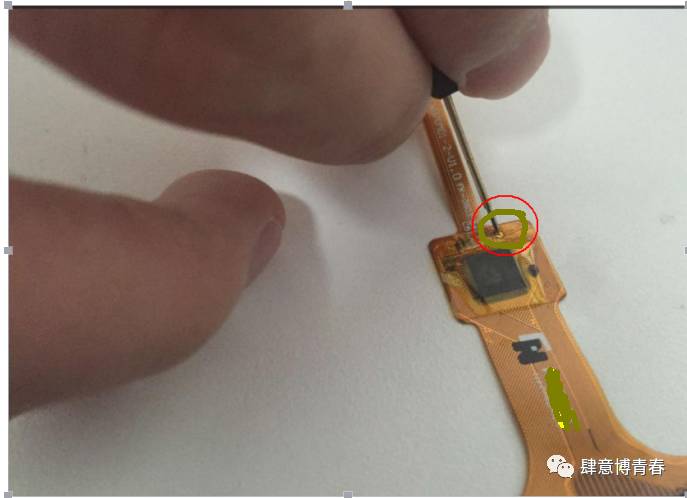
Press Run-F5 to prompt PROGRM FIRST IMAGE TEST successfully, indicating that programming was successful; the marked area can be tested.
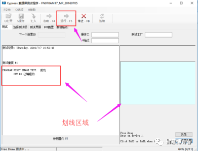
The default save directory for the production line log data: you can modify the path as needed to store test data.
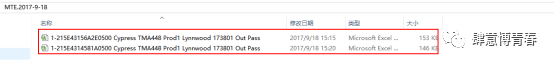
Data folder format:

Contains all Excel data:
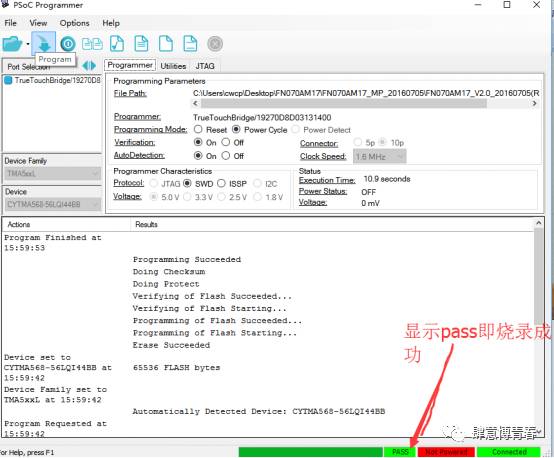
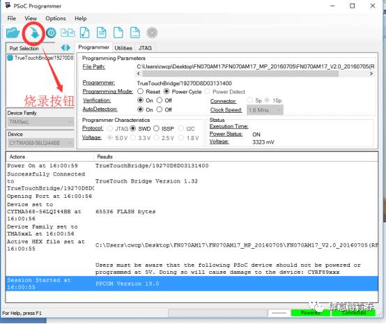
Programming Software: This software only programs and does not test, requiring the SWDIO pin
Programming requires only 4 pins, VDD, GND, SCLK (INT), SWDIO
Testing requires only 4 pins, VDD, GND, SCL, SDA
Next, proceed with programming
1: Check if the hardware devices are properly connected.
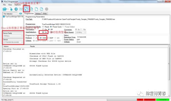
2: Start programming
3: Wait for the programming to pass, which indicates OK