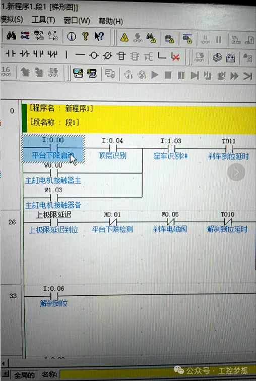
1. Adding Input Point Associated Registers to CP1E PLC
To meet the requirement of “adding associated registers for the platform drop start input point I0.00”, it is necessary to use internal relays (W) or data registers (D) to achieve state storage or data association. The specific steps are as follows:
-
Select Register Type: If you only need to store the on/off state of I0.00, it is recommended to use internal relay W area (e.g., W0.00); if you need to record the trigger count, duration, and other data of I0.00, it is recommended to use data register D area (e.g., D0).
-
Write Program Segment: In the CX-Programmer software, place the register association logic at the beginning of the program segment (ensure it is executed first). For example: State Storage (W area): Directly assign the state of I0.00 to W0.00, the program statement is:
<span class="language-plaintext">I0.00 OUT W0.00</span>. This logic implements “when I0.00 is on, W0.00 is also on; when I0.00 is off, W0.00 is also off”. -
Data Counting (D area): If you need to record the trigger count of I0.00, you need to use the rising edge instruction, the program statements are:
<span class="language-plaintext">I0.00 PLS M0.00</span>,<span class="language-plaintext">M0.00 ADD 1 D0 D0</span>. This logic implements “each time I0.00 is on, the value of D0 increases by 1”. -
Verify Program: After writing, test the logic using the “online simulation” function of CX-Programmer to ensure that the register can accurately respond to the state changes of I0.00.
2. CP1E PLC and Boke Touch Screen Connection Settings
The Boke touch screen needs to communicate with the CP1E via serial port or Ethernet, the core is to configure the same communication parameters and associate register addresses. The steps are as follows:
-
Hardware Connection: Serial Connection: Use an RS232 cable (the RS232 port of CP1E is CN2), one end connects to the PLC’s CN2 port, and the other end connects to the touch screen’s serial port (e.g., COM1).
-
Ethernet Connection: If the CP1E is a model with an Ethernet port (e.g., CP1E-E), use a network cable to connect the PLC and touch screen to the same local area network (or directly connect them).
-
Touch Screen Software Configuration: Open the Boke touch screen programming software (e.g., Kinco DTools), create a new project and select the corresponding touch screen model, then go to “Communication Settings”: Communication Protocol: Select the dedicated protocol for Omron CP series (e.g., Host Link protocol).
-
Communication Parameters: The PLC and touch screen must maintain consistency, serial port parameters (baud rate 9600/19200bps, data bits 8, stop bits 1, parity none); Ethernet parameters (the PLC’s IP address must be in the same subnet as the touch screen, e.g., PLC IP: 192.168.1.100, touch screen IP: 192.168.1.101).
-
Associate Register Address: Add controls (e.g., indicator lights, value display boxes) on the touch screen interface, and set the control’s “data address” to the register defined in the first step (e.g., W0.00 or D0), ensuring the address format meets the requirements of the Boke software (usually “W000” or “D000”).
-
Download Test: Download the configured touch screen program to the hardware, and after powering on, test whether the controls can accurately display the status or value of the PLC register.
3. CP1E PLC Wireless Connection to Computer via Router
It is necessary to use Ethernet module (if CP1E does not have a built-in Ethernet port) and a wireless router to enable communication between the computer and PLC via WiFi. The steps are as follows:
-
Hardware Preparation: If the CP1E is a model without a built-in Ethernet port (e.g., CP1E-N), an external Omron Ethernet module (e.g., CJ1W-ETN21) must be connected through the PLC’s expansion interface.
-
One wireless router (ensure it is connected to the internet), one network cable (to connect the PLC/Ethernet module to the router), and one computer with WiFi capability.
-
Configure PLC IP Address: Use the CX-Programmer software to first connect the PLC to the computer via a serial connection (RS232), then go to “Online” → “PLC Settings” → “Ethernet Settings”.
-
Set the PLC’s IP address, subnet mask, and gateway to be consistent with the router’s subnet (e.g., if the router’s gateway is 192.168.1.1, set the PLC IP to 192.168.1.XXX, subnet mask 255.255.255.0, gateway 192.168.1.1).
-
After setting, disconnect the serial connection and use a network cable to connect the PLC/Ethernet module’s port to the router’s LAN port.
-
Computer WiFi Connection Settings: Connect the computer to the WiFi network of the above router (ensure the WiFi and LAN ports are in the same subnet).
-
In the computer’s “Network and Sharing Center”, check the local connection (WiFi) IP address to confirm it is in the same subnet as the PLC (e.g., computer IP: 192.168.1.200).
-
CX-Programmer Wireless Communication Test: Open CX-Programmer, create a new project and select “CP1E” series PLC, then click “Online” → “Communication Settings”.
-
In the “Communication Method”, select “Ethernet”, click “Search”, and the software will automatically scan for CP1E PLCs in the same subnet (displaying the PLC’s IP address).
-
Select the scanned PLC, click “Connect”; if the connection is successful, you can perform program upload, download, monitoring, and other operations via WiFi.
Notes: 1. During wireless communication, ensure the router signal is stable to avoid electromagnetic interference in industrial environments; 2. If the connection fails, check whether the PLC IP and computer IP are in the same subnet, whether the router LAN port is functioning properly, and whether the firewall is blocking the communication port of CX-Programmer (e.g., TCP 9600).
Previous Recommendations
Recruitment for Electricians at Jiangxi Mingde New Materials Co., Ltd.!
Are you using the edge instruction correctly in TIA Portal?
Why should transformer voltage regulation be high to high and low to low?
Detailed application methods for Omron NX enumerations.
Secrets that repair technicians won’t tell you: Principles and applications of three-phase rectifier circuits.
Tutorial on using the TIA Portal V18 simulator.
Siemens PLC S7 communication simulation tutorial: Achieving seamless data interaction with TIA Portal.
PLC power outage data loss? 3 steps to set permanent storage of key parameters.
Using Mitsubishi PLC to add an electronic lock to the touch screen.
Tutorial on setting up installment payment functions on Wecon touch screens.
Test your skills: Are you a real electrician or a fake one? How to calculate current with 5 turns in a transformer?
TC600-2S0015G1 User Manual for Taichuan Inverter.
Configuration instructions for Wecon touch screen as OPC UA server communication.
How to use VBS scripts to automatically write WinCC7.5 data into Excel spreadsheets.
How to achieve Ethernet communication between MCGS PRO and S7-200 SMART.
How to design a vending machine that can give change using MCGS.
Usage instructions for Wecon touch screen macro command conditional assignment.
Has the Kunlun Tongtai touch screen directly controlled the inverter?
How logical operations determine the fate of draft picks.
Technical insights | PLC custom countdown timer program design is that simple.
Two PLC implementation methods for motor delayed start and stop.
How to control a park fountain with PLC to achieve multiple timing logic.
TIA Portal V19 installation tutorial: From beginner to expert, including common problem-solving and technical training benefits.