Introduction
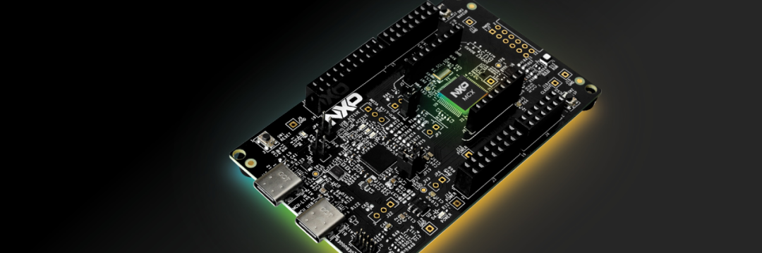
The SPI bus is developed as a four IO port communication interface consisting of: CS, SCLK, MISO, MOSI; it is commonly used for communication between CPUs and peripherals. Common SPI bus devices include: TFT LCDs, QSPI FLASH, clock modules, IMUs, etc.; the development board integrates two SPI buses. This experiment will focus on the porting process of the SPI BSP driver in the RT-Thread system, taking the NXP MCXA153 as an example.
Porting Process
Taking SPI0 as an Example
(1) Add the corresponding peripherals in the board: configure the spi0 peripheral to a reset state and set the GPIO pin functions.
(2) Add the corresponding Kconfig switch to indicate whether the corresponding peripheral is enabled or disabled (essentially by using macro definitions or conditional compilation).
(3) Write the SPI bus driver based on the SPI example project provided by SDK_2_14_2_FRDM-MCXA153, which requires implementing several key functions.
SDK_2_14_2_FRDM-MCXA153
https://mcuxpresso.nxp.com/zh/builder?hw=FRDM-MCXA153
-
rt_hw_spi_init
-
spi_configure
-
spi_transfer
(4) Add the corresponding library file dependencies: fsl_lpspi.c, fsl_lpspi_edma.c
Pin Correspondence
Driver Files
Board.
Add the following code in the function rt_hw_board_init
edma_config_t userConfig = {0}; EDMA_GetDefaultConfig(&userConfig); EDMA_Init(DMA0, &userConfig); pin_mux.cpin_mux.c
Add the following code in the function BOARD_InitPins
#ifdef BSP_USING_SPI0 RESET_ReleasePeripheralReset(kLPSPI0_RST_SHIFT_RSTn); const port_pin_config_t port1_0_pin56_config = {/* Internal pull-up/down resistor is disabled */ kPORT_PullDisable, /* Low internal pull resistor value is selected. */ kPORT_LowPullResistor, /* Fast slew rate is configured */ kPORT_FastSlewRate, /* Passive input filter is disabled */ kPORT_PassiveFilterDisable, /* Open drain output is disabled */ kPORT_OpenDrainDisable, /* Low drive strength is configured */ kPORT_LowDriveStrength, /* Normal drive strength is configured */ kPORT_NormalDriveStrength, /* Pin is configured as LPSPI0_SDO */ kPORT_MuxAlt2, /* Digital input enabled */ kPORT_InputBufferEnable, /* Digital input is not inverted */ kPORT_InputNormal, /* Pin Control Register fields [15:0] are not locked */ kPORT_UnlockRegister}; /* PORT1_0 (pin 56) is configured as LPSPI0_SDO */ PORT_SetPinConfig(PORT1, 0U, &port1_0_pin56_config); const port_pin_config_t port1_1_pin57_config = {/* Internal pull-up/down resistor is disabled */ kPORT_PullDisable, /* Low internal pull resistor value is selected. */ kPORT_LowPullResistor, /* Fast slew rate is configured */ kPORT_FastSlewRate, /* Passive input filter is disabled */ kPORT_PassiveFilterDisable, /* Open drain output is disabled */ kPORT_OpenDrainDisable, /* Low drive strength is configured */ kPORT_LowDriveStrength, /* Normal drive strength is configured */ kPORT_NormalDriveStrength, /* Pin is configured as LPSPI0_SCK */ kPORT_MuxAlt2, /* Digital input enabled */ kPORT_InputBufferEnable, /* Digital input is not inverted */ kPORT_InputNormal, /* Pin Control Register fields [15:0] are not locked */ kPORT_UnlockRegister}; /* PORT1_1 (pin 57) is configured as LPSPI0_SCK */ PORT_SetPinConfig(PORT1, 1U, &port1_1_pin57_config); const port_pin_config_t port1_2_pin58_config = {/* Internal pull-up/down resistor is disabled */ kPORT_PullDisable, /* Low internal pull resistor value is selected. */ kPORT_LowPullResistor, /* Fast slew rate is configured */ kPORT_FastSlewRate, /* Passive input filter is disabled */ kPORT_PassiveFilterDisable, /* Open drain output is disabled */ kPORT_OpenDrainDisable, /* Low drive strength is configured */ kPORT_LowDriveStrength, /* Normal drive strength is configured */ kPORT_NormalDriveStrength, /* Pin is configured as LPSPI0_SDI */ kPORT_MuxAlt2, /* Digital input enabled */ kPORT_InputBufferEnable, /* Digital input is not inverted */ kPORT_InputNormal, /* Pin Control Register fields [15:0] are not locked */ kPORT_UnlockRegister}; /* PORT1_2 (pin 58) is configured as LPSPI0_SDI */ PORT_SetPinConfig(PORT1, 2U, &port1_2_pin58_config); const port_pin_config_t port1_3_pin59_config = {/* Internal pull-up/down resistor is disabled */ kPORT_PullDisable, /* Low internal pull resistor value is selected. */ kPORT_LowPullResistor, /* Fast slew rate is configured */ kPORT_FastSlewRate, /* Passive input filter is disabled */ kPORT_PassiveFilterDisable, /* Open drain output is disabled */ kPORT_OpenDrainDisable, /* Low drive strength is configured */ kPORT_LowDriveStrength, /* Normal drive strength is configured */ kPORT_NormalDriveStrength, /* Pin is configured as LPSPI0_PCS0 */ kPORT_MuxAlt2, /* Digital input enabled */ kPORT_InputBufferEnable, /* Digital input is not inverted */ kPORT_InputNormal, /* Pin Control Register fields [15:0] are not locked */ kPORT_UnlockRegister}; /* PORT1_3 (pin 59) is configured as LPSPI0_PCS0 */ PORT_SetPinConfig(PORT1, 3U, &port1_3_pin59_config);#endifBoard/Kconfig
Add the SPI0 related configuration
menuconfig BSP_USING_SPI config BSP_USING_SPI bool "Enable SPI" select RT_USING_SPI default y if BSP_USING_SPI config BSP_USING_SPI0 bool "Enable SPI0" default endifdrv_spi.c
The SPI driver layer is modified as follows
/* * Copyright (c) 2006-2024, RT-Thread Development Team * * SPDX-License-Identifier: Apache-2.0 * * Change Logs: * Date Author Notes * 2024-08-3 hywing The first version for MCXA */#include "rtdevice.h"#include "drv_spi.h"#include "fsl_common.h"#include "fsl_lpspi.h"#include "fsl_lpspi_edma.h"#define DMA_MAX_TRANSFER_COUNT (32767)enum{#ifdef BSP_USING_SPI0 SPI1_INDEX,#endif};struct lpc_spi{ struct rt_spi_bus parent; LPSPI_Type *LPSPIx; clock_attach_id_t clock_attach_id; clock_div_name_t clock_div_name; clock_name_t clock_name; DMA_Type *DMAx; uint8_t tx_dma_chl; uint8_t rx_dma_chl; edma_handle_t dma_tx_handle; edma_handle_t dma_rx_handle; dma_request_source_t tx_dma_request; dma_request_source_t rx_dma_request; lpspi_master_edma_handle_t spi_dma_handle; rt_sem_t sem; char *name;};static struct lpc_spi lpc_obj[] ={#ifdef BSP_USING_SPI0 { .LPSPIx = LPSPI0, .clock_attach_id = kFRO12M_to_LPSPI0, .clock_div_name = kCLOCK_DivLPSPI0, .clock_name = kCLOCK_Fro12M, .tx_dma_request = kDma0RequestLPSPI0Tx, .rx_dma_request = kDma0RequestLPSPI0Rx, .DMAx = DMA0, .tx_dma_chl = 0, .rx_dma_chl = 1, .name = "spi0", },#endif};struct lpc_sw_spi_cs{ rt_uint32_t pin;};rt_err_t rt_hw_spi_device_attach(const char *bus_name, const char *device_name, rt_uint32_t pin){ rt_err_t ret = RT_EOK; struct rt_spi_device *spi_device = (struct rt_spi_device *)rt_malloc(sizeof(struct rt_spi_device)); struct lpc_sw_spi_cs *cs_pin = (struct lpc_sw_spi_cs *)rt_malloc(sizeof(struct lpc_sw_spi_cs)); cs_pin->pin = pin; rt_pin_mode(pin, PIN_MODE_OUTPUT); rt_pin_write(pin, PIN_HIGH); ret = rt_spi_bus_attach_device(spi_device, device_name, bus_name, (void *)cs_pin); return ret;}static rt_err_t spi_configure(struct rt_spi_device *device, struct rt_spi_configuration *cfg){ rt_err_t ret = RT_EOK;// struct lpc_spi *spi = RT_NULL;// spi = (struct lpc_spi *)(device->bus->parent.user_data);// ret = lpc_spi_init(spi->SPIx, cfg); return ret;}static void LPSPI_MasterUserCallback(LPSPI_Type *base, lpspi_master_edma_handle_t *handle, status_t status, void *userData){ struct lpc_spi *spi = (struct lpc_spi *)userData; rt_sem_release(spi->sem);}static rt_ssize_t spixfer(struct rt_spi_device *device, struct rt_spi_message *message){ int i; lpspi_transfer_t transfer = {0}; RT_ASSERT(device != RT_NULL); RT_ASSERT(device->bus != RT_NULL); RT_ASSERT(device->bus->parent.user_data != RT_NULL); struct lpc_spi *spi = (struct lpc_spi *)(device->bus->parent.user_data); struct lpc_sw_spi_cs *cs = device->parent.user_data; if (message->cs_take) { rt_pin_write(cs->pin, PIN_LOW); } transfer.dataSize = message->length; transfer.rxData = (uint8_t *)(message->recv_buf); transfer.txData = (uint8_t *)(message->send_buf); // if(message->length < MAX_DMA_TRANSFER_SIZE) if (0) { LPSPI_MasterTransferBlocking(spi->LPSPIx, &transfer); } else { uint32_t block, remain; block = message->length / DMA_MAX_TRANSFER_COUNT; remain = message->length % DMA_MAX_TRANSFER_COUNT; for (i = 0; i < block; i++) { transfer.dataSize = DMA_MAX_TRANSFER_COUNT; if (message->recv_buf) transfer.rxData = (uint8_t *)(message->recv_buf + i * DMA_MAX_TRANSFER_COUNT); if (message->send_buf) transfer.txData = (uint8_t *)(message->send_buf + i * DMA_MAX_TRANSFER_COUNT); LPSPI_MasterTransferEDMA(spi->LPSPIx, &spi->spi_dma_handle, &transfer); rt_sem_take(spi->sem, RT_WAITING_FOREVER); } if (remain) { transfer.dataSize = remain; if (message->recv_buf) transfer.rxData = (uint8_t *)(message->recv_buf + i * DMA_MAX_TRANSFER_COUNT); if (message->send_buf) transfer.txData = (uint8_t *)(message->send_buf + i * DMA_MAX_TRANSFER_COUNT); LPSPI_MasterTransferEDMA(spi->LPSPIx, &spi->spi_dma_handle, &transfer); rt_sem_take(spi->sem, RT_WAITING_FOREVER); } } if (message->cs_release) { rt_pin_write(cs->pin, PIN_HIGH); } return message->length;}static struct rt_spi_ops lpc_spi_ops ={ .configure = spi_configure, .xfer = spixfer};int rt_hw_spi_init(void){ int i; for (i = 0; i < ARRAY_SIZE(lpc_obj); i++) { CLOCK_SetClockDiv(lpc_obj[i].clock_div_name, 1u); CLOCK_AttachClk(lpc_obj[i].clock_attach_id); lpc_obj[i].parent.parent.user_data = &lpc_obj[i]; lpc_obj[i].sem = rt_sem_create("sem_spi", 0, RT_IPC_FLAG_FIFO); lpspi_master_config_t masterConfig; LPSPI_MasterGetDefaultConfig(&masterConfig); masterConfig.baudRate = 12 * 1000 * 1000; masterConfig.pcsToSckDelayInNanoSec = 1000000000U / masterConfig.baudRate * 1U; masterConfig.lastSckToPcsDelayInNanoSec = 1000000000U / masterConfig.baudRate * 1U; masterConfig.betweenTransferDelayInNanoSec = 1000000000U / masterConfig.baudRate * 1U; LPSPI_MasterInit(lpc_obj[i].LPSPIx, &masterConfig, CLOCK_GetFreq(lpc_obj[i].clock_name)); EDMA_CreateHandle(&lpc_obj[i].dma_tx_handle, lpc_obj[i].DMAx, lpc_obj[i].tx_dma_chl); EDMA_CreateHandle(&lpc_obj[i].dma_rx_handle, lpc_obj[i].DMAx, lpc_obj[i].rx_dma_chl); EDMA_SetChannelMux(lpc_obj[i].DMAx, lpc_obj[i].tx_dma_chl, lpc_obj[i].tx_dma_request); EDMA_SetChannelMux(lpc_obj[i].DMAx, lpc_obj[i].rx_dma_chl, lpc_obj[i].rx_dma_request); LPSPI_MasterTransferCreateHandleEDMA(lpc_obj[i].LPSPIx, &lpc_obj[i].spi_dma_handle, LPSPI_MasterUserCallback, &lpc_obj[i], &lpc_obj[i].dma_rx_handle, &lpc_obj[i].dma_tx_handle); rt_spi_bus_register(&lpc_obj[i].parent, lpc_obj[i].name, &lpc_spi_ops); } return RT_EOK;} INIT_DEVICE_EXPORT(rt_hw_spi_init);SConscript Script
Add the following code in the file Libraries/MCXA153/SConscript
if GetDepend('BSP_USING_SPI'): src += ['MCXA153/drivers/fsl_lpspi.c'] src += ['MCXA153/drivers/fsl_lpspi_edma.c']Test Case
Open menuconfig to enable the spi0 driver

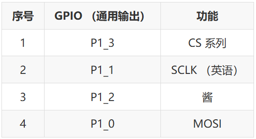
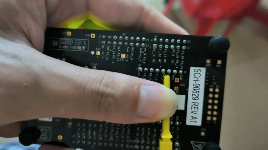
Short-circuit the MISO and MOSI pins (P1_0 and P1_2) for self-transmission and reception testing
Test Program
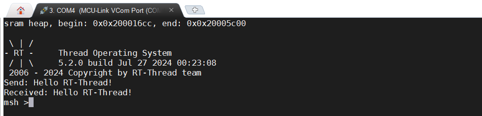
#include <rtthread.h> #include "rtdevice.h" #include "drv_spi.h"#define SPI_BUS_NAME "spi0" #define SPI_DEV_NAME "spi00" static struct rt_spi_device *spi_device;static void spi_sample(void) { rt_err_t result; struct rt_spi_configuration cfg; uint8_t tx_buf[] = "Hello RT-Thread!"; uint8_t rx_buf[sizeof(tx_buf)]; rt_base_t cs = 1*32+3; rt_hw_spi_device_attach(SPI_BUS_NAME, SPI_DEV_NAME, cs); /* Get SPI device */ spi_device = (struct rt_spi_device *)rt_device_find(SPI_DEV_NAME); if (!spi_device) { rt_kprintf("can't find %s device!\n", SPI_BUS_NAME); } /* Configure SPI device */ cfg.data_width = 8; cfg.mode = RT_SPI_MASTER | RT_SPI_MODE_0 | RT_SPI_MSB; cfg.max_hz = 12* 1000 * 1000; /* Configure SPI device */ rt_spi_configure(spi_device, &cfg); result = rt_spi_transfer(spi_device, tx_buf, rx_buf, sizeof(tx_buf)); if (result == sizeof(tx_buf)) { rt_kprintf("Send: %s\n", tx_buf); rt_kprintf("Received: %s\n", rx_buf); } else { rt_kprintf("spi transfer failed! error code: %d\n", result); } } int main(void) { spi_sample(); return 0; }Running Result
Conclusion
Additionally, you can also install and configure the clock tree and GPIO multiplexing through a graphical interface using MCUXpresso Config Tools v16
——————End——————
Want to publish content on the RT-Thread platform or community? Or want to participate in related live events and competitions? RT-Thread has opened a docking window, please contact us via email, looking forward to cooperation!
Cooperation email: [email protected] ↓ Click “Read Original” to jump to the original text