14.3.3
NVIC Interrupt Configuration Firmware Library
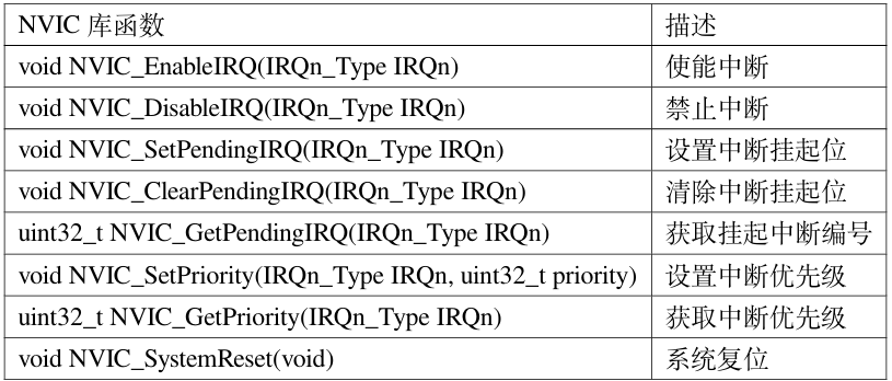
The firmware library file core_cm33.h provides several functions for NVIC, which comply with CMSIS rules and can be used by any Cortex-M33 processor, as detailed below:
Table 15-3 NVIC Library Functions Compliant with CMSIS Standards
Click to view the full image
These library functions are rarely used in programming, and often not at all. There are simpler methods for configuring interrupts, as discussed in the interrupt programming section.
14.4
RA6M5
The Renesas RA6M5 features a Cortex-M33 core, which supports numerous system exceptions and external interrupts. Except for a few exceptions with fixed priorities, all other exceptions have configurable priorities. The Cortex-M33 can support up to 480 external interrupts, with Renesas utilizing 112 in the interrupt vector table, of which 96 are configurable. The RA6M5 peripheral modules have 287 configurable interrupt events, with a maximum of 256 priority levels.
14.4.1
Interrupt Vector Table
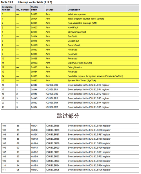
The interrupt vector table provides the corresponding interrupt service routines, commonly referred to as ISRs. The interrupt response is achieved by extracting the starting address of the ISR to perform a program counter (PC) jump. However, for the Cortex-M33 core, the RA6M5 uses 112 ISRs in the interrupt vector table. Below is the usage of ISRs for the Renesas RA6M5.
Click to view the full image
Notes
The first 16 are configured for Arm, such as the initial stack pointer, highlighted in yellow. The subsequent 96 are for configuring the ICU event selection register ICU.IELSR. For details, refer to Table 13.3 in the “RA6M5 Group User’s Manual: Hardware” for the Interrupt Vector Table.
14.4.2
ICU.IELSRn Register
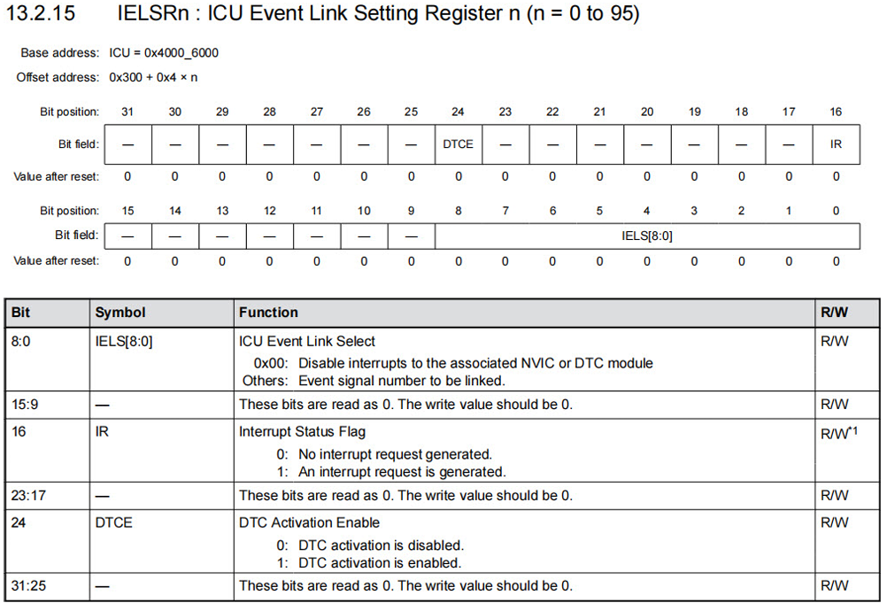
The IELSrn register selects the IRQ sources used by NVIC. IELSrn corresponds to the NVIC IRQ input source number, where n=0 to 95.
Click to view the full image
The IELS[8:0] bits link event signals to the corresponding NVIC or DTC modules. Event options are divided into 8 groups (Group 0 to 7). The IR status flag indicates a single interrupt request from the events specified in IELS[8:0]. The DTCE bit is the DTC activation enable bit; when set to 1, the corresponding event is selected as a DTC activation source.
14.4.3
Interrupt Event Table
The interrupt event table shows which interrupts can be configured in the Renesas RA6M5, such as IIC interrupts, GPT interrupts, Port interrupts, DMAC interrupts, DTC interrupts, AGT interrupts, etc. For specifics, refer to Table 13.4 in the “RA6M5 Group User’s Manual: Hardware” for the Event Table.
14.5
Introduction to the ELC Module
The Event Link Controller (ELC) connects event requests generated by various peripheral modules as source signals to different modules, allowing direct linking between modules without CPU intervention. It binds events (interrupt sources) to peripheral functions, executing the bound peripheral function when the event is triggered. You can think of this as an interrupt that does not require CPU involvement.
The relationship between event numbers and interrupt numbers: the event number linked by the event link is the same as the event number of the associated interrupt source.
ELC Features
-
219 types of event signals can be directly connected to various modules. ELC generates ELC event signals and activates DTC events.


Need Technical Support?
If you have any questions while using Renesas MCU/MPU products, you can scan the QR code below or copy the URL into your browser to access the Renesas Technical Forum for answers or online technical support.

https://community-ja.renesas.com/zh/forums-groups/mcu-mpu/
To be continued
Recommended Reading

Experiment 1: System Clock Configuration Experiment – Practical Guide to Renesas RA Series FSP Library Development (33)

Simple Software Delay Function – Practical Guide to Renesas RA Series FSP Library Development (34)

Overview of Interrupt Applications in RA Series MCUs – Practical Guide to Renesas RA Series FSP Library Development (35)