01
Introduction
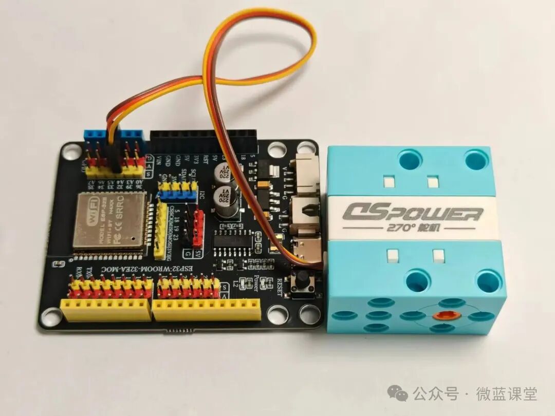
This 270-degree servo is controlled by PWM signals to adjust the rotation angle (0 to 270 degrees), capable ofinstantaneously completing angle changes, with good explosive force and strong stall torque.
This article will first discuss analog and digital signals, then introduce what PWM is, and finally demonstrate how to wire and program the 270-degree servo.
02
Principle
Analog and Digital Signals
First, let’s understand what analog and digital signals are:
- Analog Signal: The ESP32 can output a voltage between 0 and 3.3V, with parameter values and return values ranging from 0 to 1023. The analog signal transmission of the ESP32 is divided into:Analog Input (ADC) and Analog Output (DAC) two categories. The analog input (ADC) pins are divided into two groups: ADC1 channels (8 in total, 6 usable) and ADC2 channels (10 in total, some are limited).
- Digital Signal: The parameters and return values are only computer values 0 and 1, where 1 represents high level (3.3V) and 0 represents low level (0V).
PWM Pulse Width Modulation
Generally, the pins of the main control board can only be set to output 3.3V or pulled down to 0V. If you want to set an output of 1.65V, you can control it by rapidly turning the voltage on and off, adjusting the on-time and off-time to modulate the voltage value. This technique is called Pulse Width Modulation (PWM).
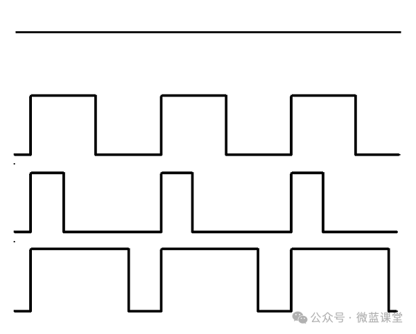
In the image above, you can see four different PWM signal graphs. They all have the same period (thus frequency), but they have different duty cycles.
- The first generated signal is 3.3V.
- The second generated signal has a 50% duty cycle, being 3.3V for half the time and 0V for the other half. As a result, the output of this signal is 1.65V instead of 3.3V.
- The third signal has a 25% duty cycle, which will output 0.825V.
- The fourth signal has a 75% duty cycle, which has three times the energy of the third signal, equivalent to an output of 2.475V.
How to Set PWM Signals in ESP32?
import machine
pin = machine.Pin(32, machine.Pin.OUT)
pwm = machine.PWM(servo_pin, freq=50)
duty = int(500 / 20000 * 1023)
pwm.duty(duty)
Servo Angle
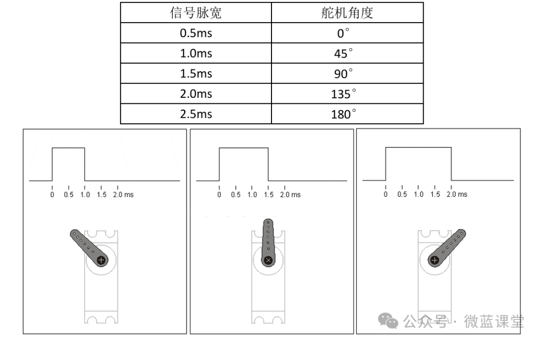
The parameters of the PWM signal in servo control are generally: period = 20ms, pulse width (high level width) range = 0.5ms to 2.5ms.

The rotation angle of the servo is determined by the pulse width. For example, if a servo has a total rotation angle of 180°, and the PWM pulse width range is 0.5ms to 2.5ms, then when the servo receives different pulse width signals, it will turn to the corresponding position (the relationship between signal pulse width and servo angle is linear):
Controlling Servo Rotation Effects
1. Servo Locking: When the signal remains unchanged, the servo will stay in its current position, and the output torque will vary depending on the load size.
2. Servo Fast Rotation: When the signal changes, such as from 1ms to 2ms, the servo will rotate from 45° to 135° at the fastest speed. This speed will depend on the servo’s performance and the load size, which is generally specified in the datasheet as the maximum rotation speed under no load.
3. Servo Slow Rotation: When a slow rotation is needed, for example, if the servo needs to turn from 45° to 135° over three seconds, you only need to calculate the incremental change in the signal pulse width, increasing from 1ms to 2ms uniformly over three seconds. The smaller the increment, the more delicate the rotation effect.
03
Wiring
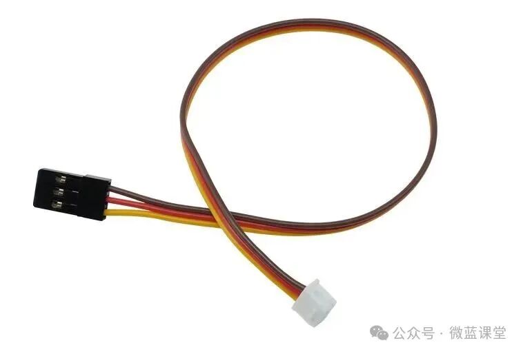
One end of the wire is a 51065 3P connector, and the other end is a JST2.54 3P connector, with three wires:
- G: Power negative, connect to GND, brown wire
- V: Power positive, connect to 3.3V, red wire
- S: Signal wire, connect to P0, yellow wire
04
Program
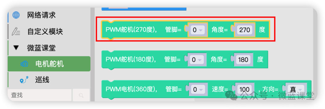
Drag the 270-degree servo into the canvas
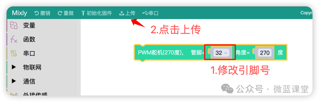
Change the pin to IO32, click upload, and you will see the servo rotate. If there is no response, it may be that the angle has already turned to that position; adjust the angle to 180 degrees and try uploading again.
05
Demonstration
Students who need components can purchase them from my Taobao store under the same name.
 Follow me for more sharing | Weilan Classroom