First, for those who want to systematically learn about Python network automation and operations, I recommend the columns by @YiXin and @ZhuJiaSheng.
Recently, “Xian Lai Wu Shi” reviewed the cross-domain solution of MPLS, simulating the Option A scheme. During the simulation, it was found that the ASBRs using OSPF protocol could not learn routes due to the OSPF down bit affecting route calculation. It is important to periodically review these issues; otherwise, we might forget them. In our current network environment, ASBRs use static routes, and we had not previously paid attention to this issue. Since we have many H3C devices, today I will share the MPLS Option A environment using the H3C simulator to simulate the experimental scenario for mutual improvement.
Networking Requirements:
(1) IBGP within AS100 and AS200, with P devices configured as RR reflectors to establish VPNv4 BGP neighbor relationships.
(2) OSPF protocol is used between ASBRs.
Key Focus/Learning:
In a BGP/MPLS VPN environment, PE devices use BGP to transmit routing information, while PE-CE uses OSPF for route learning and transmission. Due to networking requirements, the command vpn-instance-capability simple needs to be configured on the PE devices to disable OSPF route loop detection and not check the DN Bit, allowing all OSPF routes to be calculated directly.
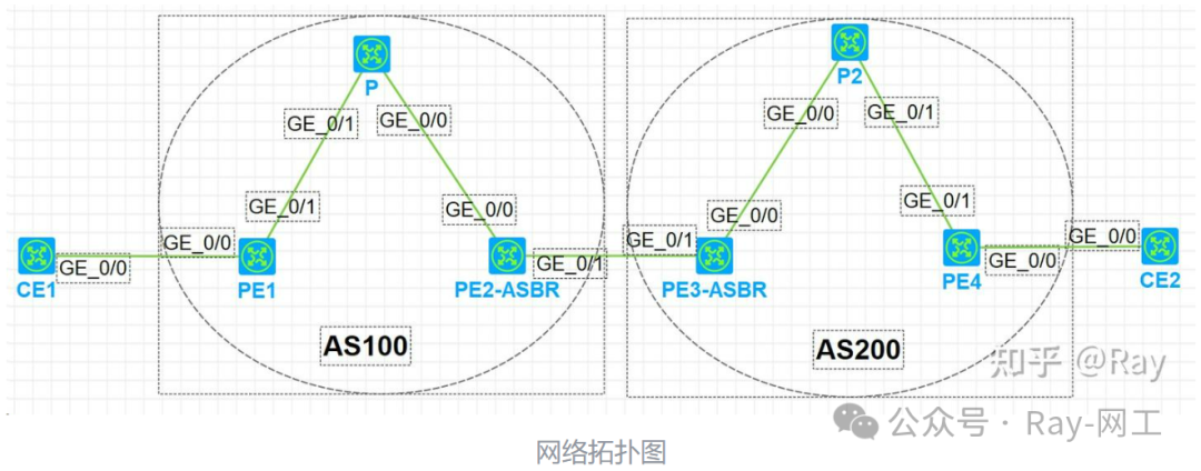
Experimental Topology Diagram:
Network Planning:
| Device Name | Interface | IP Address | Remarks |
|---|---|---|---|
| CE1 | G0/0 | 192.168.12.1/24 | PE-CE uses OSPF protocol |
| Loopback0 | 1.1.1.1/32 | ||
| PE1 | G0/0 | 192.168.12.2/24 | |
| G0/1 | 192.168.23.2/24 | PE-CE uses OSPF protocol | |
| Loopback0 | 2.2.2.2/32 | PE-P uses IBGP protocol | |
| P | G0/1 | 192.168.23.3/24 | |
| G0/0 | 192.168.34.3/24 | ||
| Loopback0 | 3.3.3.3/32 | ||
| PE2-ASBR | G0/0 | 192.168.34.4/24 | OSPF protocol is used between ASBRs |
| G0/1 | 192.168.45.4/24 | ||
| Loopback0 | 4.4.4.4/32 | ||
| PE3-ASBR | G0/1 | 192.168.45.5/24 | OSPF protocol is used between ASBRs |
| G0/0 | 192.168.56.5/24 | ||
| Loopback0 | 5.5.5.5/32 | ||
| P2 | G0/0 | 192.168.56.6/24 | |
| G0/1 | 192.168.67.6/24 | ||
| Loopback0 | 6.6.6.6/32 | ||
| PE4 | G0/1 | 192.168.67.7/24 | PE-P uses IBGP protocol |
| G0/0 | 192.168.78.7/24 | PE-CE uses OSPF protocol | |
| Loopback0 | 7.7.7.7/32 | ||
| CE2 | G0/0 | 192.168.78.8/24 | PE-CE uses OSPF protocol |
| Loopback0 | 8.8.8.8/32 |
Configuration Steps:
(1) Configure CE1 Router:
# Configure OSPF protocol
ospf 2
 area 0.0.0.0
  network 1.1.1.1 0.0.0.0
  network 192.168.12.0 0.0.0.3
#
interface LoopBack0
 ip address 1.1.1.1 255.255.255.255
#
interface GigabitEthernet0/0
 port link-mode route
 combo enable copper
 ip address 192.168.12.1 255.255.255.0
(2) Configure PE1 Router:
# Configure VPN instance
ip vpn-instance a
 route-distinguisher 1:1
 vpn-target 1:100 import-extcommunity
 vpn-target 1:100 export-extcommunity
# Backbone OSPF protocol
ospf 1
 area 0.0.0.0
# PE and CE OSPF protocol
ospf 2 vpn-instance a
 import-route bgp
 area 0.0.0.0
  network 192.168.12.0 0.0.0.255
# Global MPLS configuration
 mpls lsr-id 2.2.2.2
 mpls ldp
#
interface GigabitEthernet0/0
 port link-mode route
 combo enable copper
 ip binding vpn-instance a
 ip address 192.168.12.2 255.255.255.0
#
interface GigabitEthernet0/1
 port link-mode route
 combo enable copper
 ip address 192.168.23.2 255.255.255.0
 ospf 1 area 0.0.0.0
 mpls enable
 mpls ldp enable
#
interface GigabitEthernet0/2
 port link-mode route
 combo enable copper
 ip address 192.168.24.2 255.255.255.0
 ospf 1 area 0.0.0.0
 mpls enable
 mpls ldp enable
# Configure VPNv4 BGP
bgp 100
 peer 3.3.3.3 as-number 100
 peer 3.3.3.3 connect-interface LoopBack0
 #
 address-family vpnv4
  peer 3.3.3.3 enable
 #
 ip vpn-instance a
  #
  address-family ipv4 unicast
   import-route ospf 2
(3) Configure P Router:
# Backbone OSPF protocol
ospf 1
 area 0.0.0.0
# Global MPLS configuration
 mpls lsr-id 3.3.3.3
 mpls ldp
#
interface LoopBack0
 ip address 3.3.3.3 255.255.255.255
 ospf 1 area 0.0.0.0
#
interface GigabitEthernet0/0
 port link-mode route
 combo enable copper
 ip address 192.168.34.3 255.255.255.0
 ospf 1 area 0.0.0.0
 mpls enable
 mpls ldp enable
#
interface GigabitEthernet0/1
 port link-mode route
 combo enable copper
 ip address 192.168.23.3 255.255.255.0
 ospf 1 area 0.0.0.0
 mpls enable
 mpls ldp enable
# Configure VPNv4 BGP
bgp 100
 peer 2.2.2.2 as-number 100
 peer 2.2.2.2 connect-interface LoopBack0
 peer 4.4.4.4 as-number 100
 peer 4.4.4.4 connect-interface LoopBack0
 #
 address-family vpnv4
  undo policy vpn-target
  peer 2.2.2.2 enable
  peer 2.2.2.2 reflect-client
  peer 4.4.4.4 enable
  peer 4.4.4.4 reflect-client
(4) Configure PE2-ASBR Router:
# Configure VPN instance
ip vpn-instance a
route-distinguisher 1:1
vpn-target 1:100 import-extcommunity
vpn-target 1:100 export-extcommunity
# Backbone OSPF protocol
ospf 1
area 0.0.0.0
# Configure OSPF protocol between ASBRs
ospf 2 vpn-instance a
import-route bgp allow-ibgp
vpn-instance-capability simple
area 0.0.0.0
network 192.168.45.0 0.0.0.255
# Global MPLS configuration
mpls lsr-id 4.4.4.4
mpls ldp
#
interface LoopBack0
ip address 4.4.4.4 255.255.255.255
ospf 1 area 0.0.0.0
#
interface GigabitEthernet0/0
port link-mode route
combo enable copper
ip address 192.168.34.4 255.255.255.0
ospf 1 area 0.0.0.0
mpls enable
mpls ldp enable
#
interface GigabitEthernet0/1
port link-mode route
combo enable copper
ip binding vpn-instance a
ip address 192.168.45.4 255.255.255.0
#
interface GigabitEthernet0/2
port link-mode route
combo enable copper
ip address 192.168.24.4 255.255.255.0
ospf 1 area 0.0.0.0
mpls enable
mpls ldp enable
# Configure VPNv4 BGP
bgp 100
peer 3.3.3.3 as-number 100
peer 3.3.3.3 connect-interface LoopBack0
#
address-family vpnv4
peer 3.3.3.3 enable
#
ip vpn-instance a
#
address-family ipv4 unicast
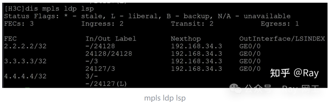
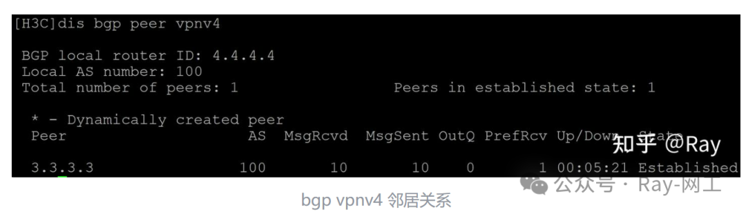
import-route ospf 2(5) The configuration for area AS200 is the same as for AS100, so it will not be displayed here. After completing the configuration, let’s check the MPLS LSP, BGP neighbor relationships, and VPN routing table of the PE2-ASBR device:
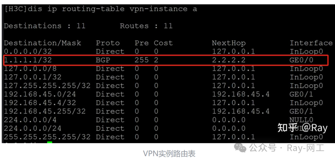
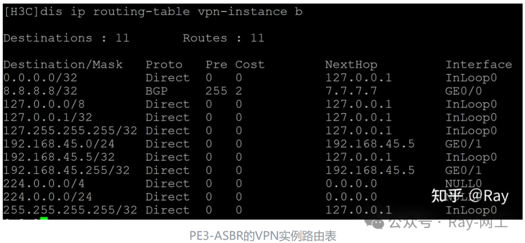
By observing the VPN instance routing table of PE2-ASBR, we can see that the route for CE1 already exists. Next, let’s check the routing table of the opposite ASBR; the route for CE1 does not appear in the routing table:
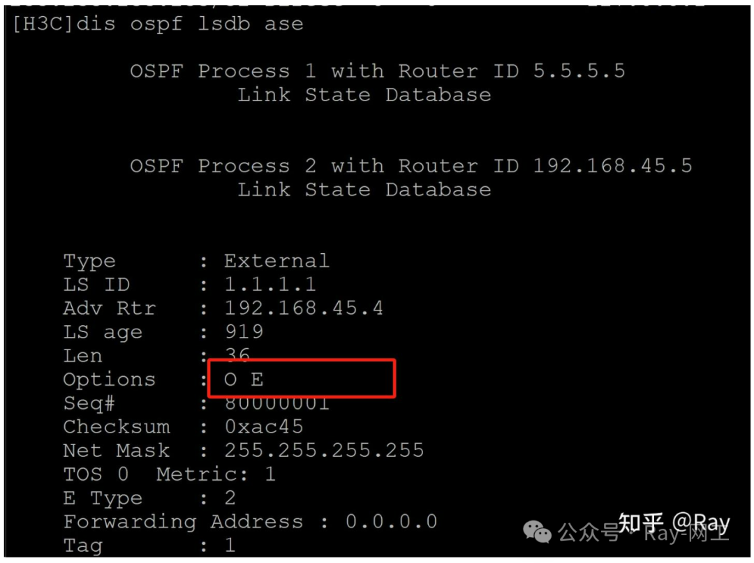
Next, let’s look at the OSPF LSDB of PE3-ASBR. By executing dis ospf lsdb summary, we can see that the route for CE1 already exists in the OSPF link-state database. However, due to the OSPF protection mechanism, the DN bit causes this information not to participate in route calculation:

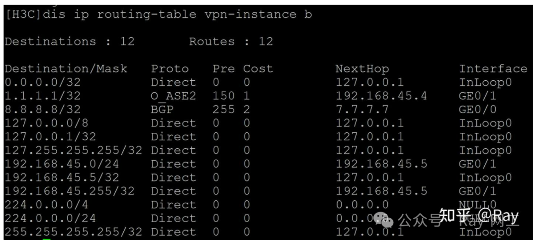
(6) Next, we will configure the vpn-instance-capability simple command in OSPF 2 of PE2-ASBR, and then observe the routing situation of the opposite ASBR:
#
ospf 2 vpn-instance a
 import-route bgp allow-ibgp
 vpn-instance-capability simple
 area 0.0.0.0
  network 192.168.45.0 0.0.0.255
The routing table of the opposite VPN instance has now learned the route for CE1:
Now let’s check the OSPF LSDB database; the DN bit for CE1 is no longer set: