This article explains the Modbus TCP communication operation between the Newland industrial barcode scanner and Mitsubishi PLC.
1. Environment
PLC: FX5U-32MR/ES, with supporting software GX Works3
Barcode Scanner: Soldier300 V2, with supporting software NSet, configured as a Modbus TCP client
2. Configuration on the Scanner Side
The configuration of the scanner can refer to the article “Modbus TCP Communication Between Newland Industrial Barcode Scanner and PLC – Siemens Edition”, where the settings for Soldier300 are described in detail, and will not be elaborated here.
Other models of Newland barcode scanners that support the Modbus TCP protocol can also refer to this.
3. Configuration on the PLC Side
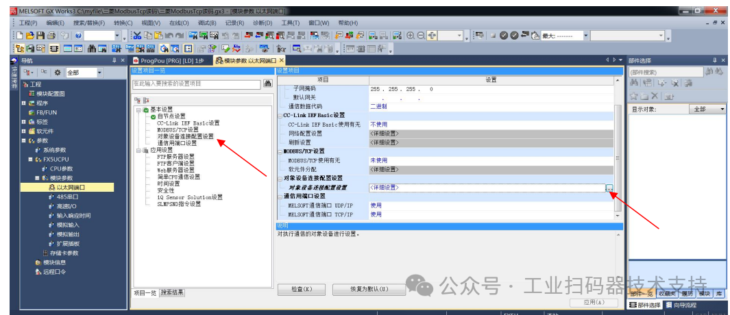
1. 【Navigation Window】——[Parameters]——FX5UCPU——[Module Parameters]——[Ethernet Port]——[Basic Settings]——[Object Device Connection Configuration Settings]
Double-click on 【Object Device Connection Configuration Settings】’s <Detailed Settings>, as shown in the figure below:
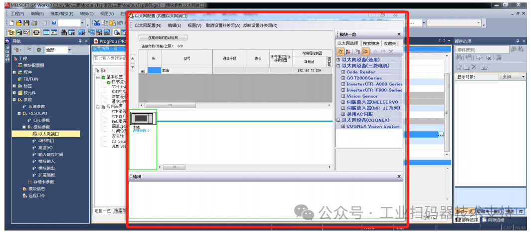
2. The pop-up Ethernet configuration window, as shown in the figure below:
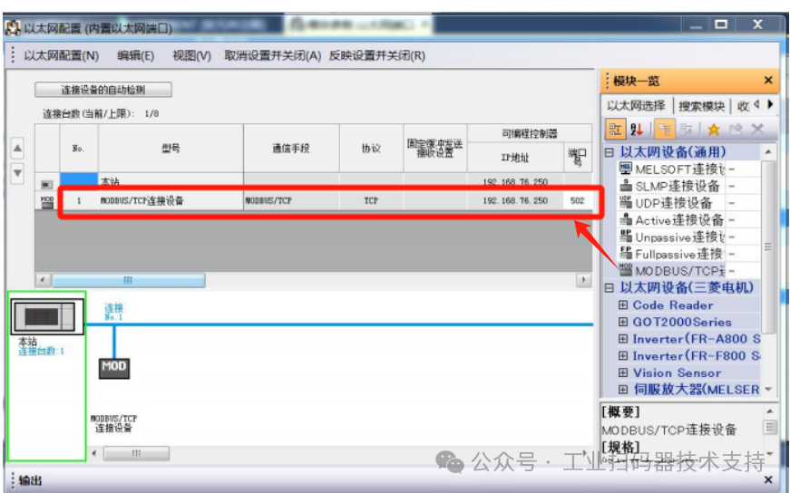
3. Drag 【Module Overview】→【Ethernet Device (General)】’s 【MODBUS/TCP Connection Device】 to the left side of the screen, and set the port number to 502 (ensure it matches the scanner)
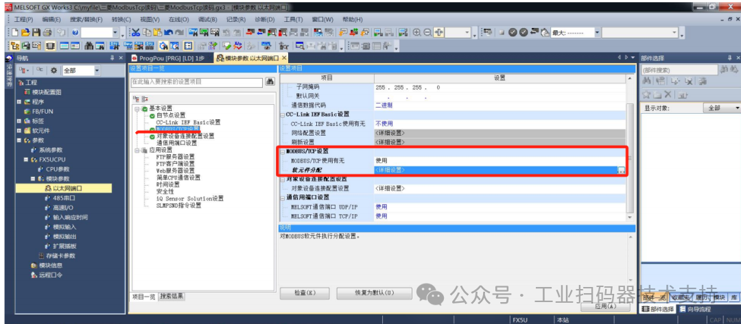
4. 【Navigation Window】——[Parameters]——FX5UCPU——[Module Parameters]——[Ethernet Port]——[Basic Settings]——[MODBUS/TCP Settings]
Double-click on 【Soft Element Allocation】’s <Detailed Settings>, as shown in the figure below:
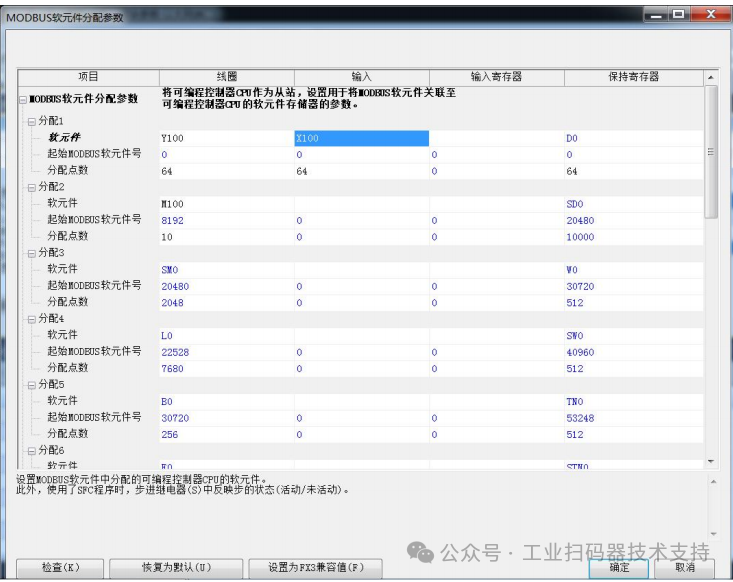
5. In the pop-up soft element allocation parameter window, make the following settings:
① Coils: Set to an address not occupied by PLC hardware or program, here set to Y100, corresponding to the scanner’s Modbus TCP decode success/failure feedback;
The starting MODBUS soft element number is set to 0 by default, corresponding to the scanner’s Modbus TCP decode feedback starting address, which is also set to 0; the number of points allocated is set according to actual needs, here it is set to 64 by default.
② Inputs: Set to an address not occupied by PLC hardware or program, here set to X100, corresponding to the scanner’s Modbus TCP trigger, discrete address set to 0 by default;
The starting MODBUS soft element number is set to 0 by default, corresponding to the scanner’s Modbus TCP trigger discrete address, which is also set to 0; the number of points allocated is set according to actual needs, here it is set to 64 by default.
③ Holding Registers: Set to an address not used by the PLC program, here set to D0, corresponding to the scanner’s write holding register;
The starting MODBUS soft element number is set to 0 by default, corresponding to the scanner’s write holding register starting address, which is also set to 0; the number of points allocated is set according to actual needs, here it is set to 64 (note that this value must be larger than the value set on the scanner side for writing holding registers).
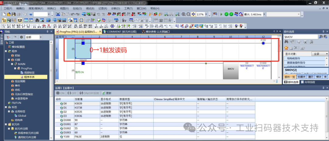
6. Each time M0 in X100 changes from 0 to 1, it triggers the scanner to scan, and the scan result can be monitored in D0 or D1000.
4. DEMO
To help users get started quickly, a DEMO “Mitsubishi FX5U ModbusTcp.gx3” is also provided for reference.