In motor control scenarios, automatic delay stop and adjustable operating parameters are common requirements to enhance operational convenience and equipment safety. The timer function of Mitsubishi PLC, combined with the power-off retention register, can efficiently implement such control logic. This article takes “motor delay start and stop + adjustable running time” as an example, detailing the timer application techniques of the Mitsubishi FX3U series PLC, including I/O allocation, program design logic, and power-off saving implementation methods, closely aligned with actual industrial site needs.
1. Clear Control Requirements: Core Indicators of Motor Delay Control
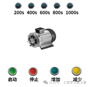
This control task revolves around an electric motor, requiring the realization of four core functions: start, delay stop, time adjustment, and status indication. The specific actions are described as follows, providing a clear basis for program design:
-
Basic Start/Stop Control: Pressing the start button (X0) immediately runs the motor; pressing the stop button (X1) immediately stops the motor, with a higher priority than the delay stop function; after the motor runs, it automatically stops after the set time.
-
Adjustable Running Time: The running time of the motor can be adjusted using the “increase button” (X2) and “decrease button” (X3), with each press increasing or decreasing the time by 10 seconds, limited to a range of 60 seconds (minimum) to 1000 seconds (maximum).
-
Power-off Saving Function: The adjusted running time parameters must have power-off saving characteristics to avoid loss of parameters after power failure, eliminating the need for reconfiguration.
-
Status Indication Function: Five indicator lights (Y1-Y5) provide feedback on time progress. When the running time reaches 200 seconds, Y1 lights up; at 400 seconds, Y2 lights up; at 600 seconds, Y3 lights up; at 800 seconds, Y4 lights up; and at 1000 seconds, Y5 lights up.
2. I/O Allocation: Building the Control Bridge Between PLC and External Devices
I/O allocation is the foundation of PLC program design, requiring clear identification of input signals (buttons) and output signals (motor, indicator lights) corresponding to PLC terminals, ensuring that hardware wiring matches program instructions. This case involves a total of 4 input points and 6 output points, with specific allocations as shown in the table below:
|
Signal Type |
PLC Terminal |
Corresponding Device |
Function Description |
|---|---|---|---|
|
Input Signal |
X0 |
Start Button |
Triggers motor start |
|
X1 |
Stop Button |
Emergency stop of motor operation |
|
|
X2 |
Time Increase Button |
Motor running time +10 seconds |
|
|
X3 |
Time Decrease Button |
Motor running time -10 seconds |
|
|
Output Signal |
Y0 |
Motor Control Terminal |
Y0 sets motor running, resets motor to stop |
|
Y1 |
Indicator Light 1 |
Lights up when running time ≥ 200 seconds |
|
|
Y2 |
Indicator Light 2 |
Lights up when running time ≥ 400 seconds |
|
|
Y3 |
Indicator Light 3 |
Lights up when running time ≥ 600 seconds |
|
|
Y4 |
Indicator Light 4 |
Lights up when running time ≥ 800 seconds |
|
|
Y5 |
Indicator Light 5 |
Lights up when running time ≥ 1000 seconds |
3. Core Ideas of Program Design: From Logical Decomposition to Instruction Implementation
This program design centers on the Mitsubishi FX3U PLC, fully utilizing its timer (T0), power-off retention register (D512), and basic logic instructions to meet control requirements. The program can be decomposed into four major modules: “motor start/stop control”, “time parameter adjustment”, “power-off saving assurance”, and “indicator light control”, with each module logically independent yet interrelated.
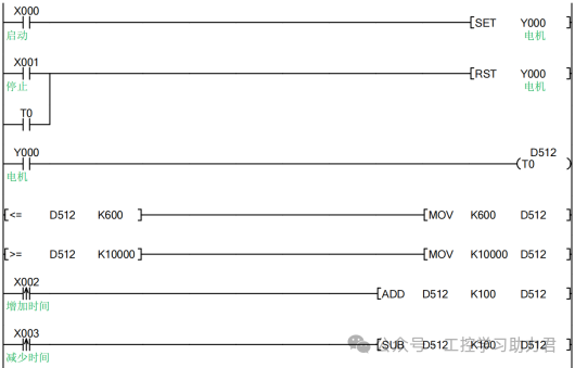
1. Motor Start/Stop Control: Start Set and Delay/Emergency Stop Reset
The core of the motor start/stop logic is “start set, dual reset”, achieved through SET/RST instructions in conjunction with the timer:
-
Start Logic: When the normally open contact of the start button X0 closes, it triggers the SET Y0 instruction, setting Y0 and maintaining it, thus starting the motor; simultaneously, the normally open contact of Y0 closes, providing a trigger condition for timer T0.
-
Stop Logic: Set dual stop trigger conditions, resetting Y0 if either condition is met: either the stop button X1 is pressed (normally open contact of X1 closes), or the timer T0 reaches the set value (normally open contact of T0 closes). In both cases, the RST Y0 instruction is executed, stopping the motor.
It should be noted that the set value of timer T0 is provided by register D512, rather than a fixed value, leaving an interface for time adjustment functionality.
2. Time Parameter Adjustment: Button Trigger and Range Limitation
The time adjustment logic is implemented through “button rising edge triggers for add/subtract instructions + comparison instructions to limit range”, ensuring precise parameter adjustment that meets requirements:
-
Unit Conversion Explanation: The timer of Mitsubishi FX3U PLC operates at a 100ms level (T0-T199), meaning the set value K1 corresponds to 0.1 seconds. Therefore, 10 seconds corresponds to set value K100, 60 seconds corresponds to K600, and 1000 seconds corresponds to K10000; all time parameters in the program are converted accordingly.
-
Add/Subtract Control: To prevent continuous parameter changes due to long button presses, rising edge detection instructions (such as PLS) capture the press actions of X2 and X3, triggering the add/subtract operation only once per press: when X2 is pressed, D512 increments by K100 (increasing by 10 seconds); when X3 is pressed, D512 decrements by K100 (decreasing by 10 seconds).
-
Range Limitation: Use CMP (compare) instructions and MOV (transfer) instructions to implement parameter boundary control: when D512 ≤ K600, automatically transfer K600 to D512, ensuring a minimum time of 60 seconds; when D512 ≥ K10000, automatically transfer K10000 to D512, ensuring a maximum time of 1000 seconds.
3. Power-off Saving Implementation: Using Power-off Retention Register D512
Ordinary registers lose data after the PLC is powered off, while the D512-D7999 registers of the Mitsubishi FX3U PLC are power-off retention registers, capable of long-term data retention after power failure without the need for additional batteries or storage modules. In this design, the set value of motor running time is stored in D512, inherently possessing power-off saving functionality, solving the parameter loss issue.
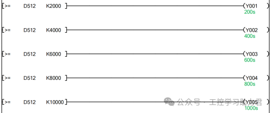
4. Indicator Light Control: Condition Trigger Based on Time Thresholds
The indicator light logic is implemented through “comparison instructions to determine time thresholds”; when the motor running time reaches the corresponding conditions, the indicator lights are triggered to light up and maintain their state (until the motor stops):
-
Compare the current value of timer T0 (reflecting the motor’s running time) with the set values of each time threshold; when T0 ≥ K2000 (200 seconds), Y1 is set; when T0 ≥ K4000 (400 seconds), Y2 is set; and so on until T0 ≥ K10000 (1000 seconds), when Y5 is set.
-
The reset logic of the indicator lights is linked to the motor; when Y0 resets (motor stops), the RST instruction resets Y1-Y5 uniformly, preparing for the next operation.
4. Key Points for Program Debugging: Ensuring Stable and Reliable Control Logic
After downloading the program to the PLC, the following steps must be followed for debugging to eliminate logical loopholes and hardware issues, ensuring stable operation on-site:
-
Hardware Wiring Check: Confirm that the input buttons (X0-X3) are securely wired to the PLC input terminals, the motor control circuit (Y0) is in series with the contactor coil, and the indicator lights (Y1-Y5) are in series with current-limiting resistors to avoid short circuits that could damage equipment.
-
Parameter Initialization Verification: After powering on the PLC, monitor the initial value of D512 through programming software; if it has not been set, manually write K600 (60 seconds) to ensure the initial time meets the lower limit requirement.
-
Functional Module Testing: Test the four major functions separately: start delay stop (after pressing X0, observe whether the motor stops according to the D512 set time), emergency stop (press X1 during operation, check if the motor stops immediately), time adjustment (press X2/X3, observe whether D512 changes in 10-second increments and does not exceed the 60-1000 seconds range), and indicator lights (during operation, observe whether Y1-Y5 light up according to the time thresholds).
-
Power-off Saving Test: Adjust D512 to any value (e.g., 300 seconds), power off the PLC for 10 seconds, then power it back on, and monitor whether the value of D512 remains unchanged to verify the power-off saving function.
5. Application Expansion: Flexible Extension of Timer Functionality
The core logic of this case can be flexibly extended to more industrial scenarios: if sequential delay start control of multiple motors is required, additional timers and output points can be added, triggering the timer of the next motor through the running signal of the previous motor; if more precise time control (e.g., at the 1-second level) is needed, a 10ms level timer (T200-T245) can be selected, and the conversion ratio of the set values can be adjusted; if remote modification of time parameters is required, D512 can be associated with a touch screen for visual operation.
Although the timer function of Mitsubishi PLC is basic, it can achieve complex control requirements when combined with registers, comparison instructions, etc. The key lies in clarifying control logic, reasonably allocating I/O resources, and utilizing PLC hardware features (such as power-off retention registers) to simplify design, ultimately achieving stable and efficient industrial control solutions.
You’ve read this far, why not follow and give a thumbs up? The more people who share and like, the more motivated I am to update!